JP2004193741A - Image scanner - Google Patents
Image scanner Download PDFInfo
- Publication number
- JP2004193741A JP2004193741A JP2002356663A JP2002356663A JP2004193741A JP 2004193741 A JP2004193741 A JP 2004193741A JP 2002356663 A JP2002356663 A JP 2002356663A JP 2002356663 A JP2002356663 A JP 2002356663A JP 2004193741 A JP2004193741 A JP 2004193741A
- Authority
- JP
- Japan
- Prior art keywords
- document
- original
- shading correction
- image
- unit
- Prior art date
- Legal status (The legal status is an assumption and is not a legal conclusion. Google has not performed a legal analysis and makes no representation as to the accuracy of the status listed.)
- Pending
Links
Images


Abstract
Description
【0001】
【発明の属する技術分野】
本発明は、複数枚の原稿を連続転送可能で、かつ原稿を反転し、原稿の両面を読み取り可能にさせる原稿自動搬送手段を備え、該原稿自動搬送手段によって搬送された原稿の画像を読み取る画像読み取り装置に関する。
【0002】
【従来の技術】
従来、原稿自動搬送手段を備え、該原稿自動搬送手段によって搬送された原稿の画像を読み取る画像読み取り装置として、複写機が知られている。
【0003】
このような複写機では、原稿自動搬送装置で原稿を読み取り装置の原稿台ガラスに移動・載置後に、照明光源を搭載したミラーユニットを原稿台ガラス上に移動させることにより、原稿の画像を読み取るようにしていた。
【0004】
しかし、最近では単位時間当たりの原稿読み取り枚数を増加させるために、ミラーユニットを所定位置で固定し、原稿自動搬送装置で原稿を読み取り装置に送りながら原稿画像を読み取る、いわゆる流し読み方式が採用されつつある。
【0005】
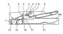
図1は、このよう流し読み方式を採用したカラー複写機の構成を示す断面図である。
【0006】
同図において、カラー複写機は、原稿自動搬送装置200と、イメージスキャナ部201と、プリンタ部202とにより、主として構成されている。
【0007】
原稿自動搬送装置200は、原稿をイメージスキャナ部201に搬送する。
【0008】
イメージスキャナ部201は、原稿を読み取り、デジタル信号処理を行う。
【0009】
また、プリンタ部202は、イメージスキャナ部201で読み取られた原稿画像に対応した画像を記録用紙にフルカラーでプリント出力する。
【0010】
イメージスキャナ部201において、原稿台ガラス203上の原稿204は、キセノン管ランプ205の光で照射され、原稿からの反射光は反射ミラー206および207に導かれ、レンズ209により3ラインセンサ210上に結像される。3ラインセンサ210は、反射光から、フルカラー情報である、レッド(R)成分、グリーン(G)成分およびブルー(B)成分にそれぞれ対応する電気信号を取り出して、信号処理部211に送信する。
【0011】
信号処理部211では、送信された各電気信号に所定の信号処理を行い、プリンタ部202に出力する。プリンタ部202では、この信号に基づいて、原稿の複写画像を形成する。
【0012】
なお、キセノン管ランプ205および反射ミラー206を有する第1のミラーユニット208は速度vで、反射ミラー207を有する第2のミラーユニット2071は速度v/2で、3ラインセンサ210の電気的走査方向に対して垂直方向に、図示しないモータにより駆動されて、原稿全面が走査される。
【0013】
また、原稿自動搬送装置200を用いて原稿を流し読み方式で読み取る場合には、第1のミラーユニット208を流し読み原稿読み取りガラス14の下に保持し、原稿を原稿自動搬送装置200で連続して搬送することにより、原稿の連続読み取りを短時間で実現できる。
【0014】
図2は、原稿自動搬送装置200の構成を示す断面図であり、図3は、この原稿自動搬送装置200によって原稿204が送られる様子を説明するための図である。
【0015】
図3において、原稿204を原稿給紙トレイ9に置き、原稿の読み取り動作を開始すると、給紙ローラ8が原稿204上に下がり((a))、原稿204の最上紙がピックアップされ、原稿204は、搬送ローラ6の回転によりレジストローラ下3およびレジストローラ上4に搬送される。レジストローラ下3およびレジストローラ上4ではシートにループが形成され、シートの斜行が補正される((b))。
【0016】
次に、原稿204は、ローラ2により搬送ローラ大1に押しつけられ、搬送ローラ大1の回転に応じて搬送され、リードコロ小13により原稿204が搬送ローラ大1から離れることを防止する((c))。
【0017】
次に、原稿204は、流し読み原稿読み取りガラス14上に搬送され、原稿画像表面の読み取りがなされ、原稿204は、リードコロ大12により搬送ローラ大1からの分離を防止しながら、排紙ローラ上11および排紙ローラ下10に搬送される((d))。
【0018】
次に、原稿204は排紙ローラ上11および排紙ローラ下10により排紙トレイ15上に一旦搬送され((e))、ここで排紙ローラ上11および排紙ローラ下10を逆回転させることにより原稿204は反転された状態でローラ2まで搬送される((f))。ローラ2では、再びループが形成されシートの斜行が補正される((g))。
【0019】
次に、原稿204は、ローラ2により搬送ローラ大1に押しつけられ、搬送ローラ大1の回転に応じて搬送され、リードコロ小13により原稿204が搬送ローラ大1から離れることを防止する((h))。次に、原稿204は、流し読み原稿読み取りガラス14上に搬送され、原稿画像裏面の読み取りがなされ、原稿204は、リードコロ大12により搬送ローラ大1からの分離を防止しながら、排紙ローラ上11および排紙ローラ下10に搬送される((i))。そして、原稿204は排紙ローラ上11および排紙ローラ下10により排紙トレイ15上に一旦搬送される。((j))。
【0020】
この時点で、原稿は原稿給紙トレイ9に載置された状態と裏返した状態になっているため、排紙された原稿が原稿給紙トレイ9に載置されたときと同じ向きとなるように、更に原稿を反転させるために、排紙ローラ上11および排紙ローラ下10を逆回転させることにより、原稿204は、反転された状態でローラ2まで搬送される((k))。ローラ2では、再びループが形成されシートの斜行が補正される((l))。
【0021】
次に、原稿204は、ローラ2により搬送ローラ大1に押しつけられ、搬送ローラ大1の回転に応じて搬送され、リードコロ小13により原稿204が搬送ローラ大1から離れることを防止する((m))。そして、原稿204は、流し読み原稿読み取りガラス14上に搬送され、リードコロ大12により搬送ローラ大1からの分離を防止しながら、排紙ローラ上11および排紙ローラ下10に搬送され((n))、排紙ローラ上11および排紙ローラ下10により排紙トレイ15に排紙される((o))。
【0022】
複数枚の原稿を読み取る場合には、以下、(a)から(o)の動作を原稿給紙トレイ9に載置された原稿がなくなるまで繰り返し続ける。
【0023】
ここで、ローラ2、リードコロ小13およびリードコロ大12は、図示しないバネにより搬送ローラ大1に所定の圧力で押し付けられている。
【0024】
また、搬送ローラ大1は、原稿204が流し読み原稿読み取りガラス14に衝突する際のショックを吸収するように、図示しないバネで所定の圧力で流し読み原稿読み取りガラス14に押し付けられている。
【0025】
ここでは、原稿1枚を読み取る場合について説明したが、複数枚連続で読み取る場合には、各原稿搬送に所定の間隔をあけて、同様の動作を繰り返し続けることになる。
【0026】
また、原稿を流し読み取り方式で読み取るときには、原稿を短時間に連続で読み取ることになるため、公知であるシェーディング補正のための標準白板の読み取りは1枚目の原稿を読み取る前にのみ行われ、原稿給氏トレイ9に載置された原稿204が全部読み取られるまでは、その読み取りデータを基に作成されたシェーディング補正係数を使用し続けることになる。
【0027】
更に、単位時間当たりに読み取れる原稿枚数を増加させるためには、原稿をCCD(Charged Coupled Device)ラインセンサなどで走査する速度を増加させることになる。CCDラインセンサは、原稿を走査する速度と出力信号レベルが反比例するため、原稿読み取り速度を上げても画質を劣化させないためには、原稿を照射する光源の光量を増加することが必要となる。
【0028】
【発明が解決しようとする課題】
しかし、上記従来の画像読み取り装置において、両面原稿を読み取る場合には、上述のように一枚の原稿に対して原稿を反転させる動作が2度必要となるため、原稿給紙トレイ9に載置された原稿が多い場合には、全ての原稿を読み取り終わるまでの時間が非常に長くなるため、原稿を照明する光源の光量変動が無視できないレベルとなってしまい、原稿を読み取った画質が劣化してしまうという欠点があった。
【0029】
更に、画面原稿の、単位時間当たりの読み取り枚数を画質劣化なく増加させるためには、原稿を照射する光源の光量を増加させなければならず、これにより、光源の昇温が激しくなったり、ランプの発光スペクトルが変動したり、更には装置全体が昇温したりして、CCDラインセンサの感度特性等に変動が生じてしまうなどの欠点があった。
【0030】
本発明は、これら点に着目してなされたものであり、両面原稿を複数枚短時間で、かつ画質劣化がない状態で読み取ることが可能な画像読み取り装置を提供することを目的とする。
【0031】
【課題を解決するための手段】
上記目的を達成するため、請求項1に記載の発明は、複数枚の原稿を連続転送可能で、かつ原稿を反転し、原稿の両面を読み取り可能にさせる原稿自動送り手段と、原稿を照明する照明手段と、原稿画像をライン毎に電気信号に変換する光電変換手段と、原稿の反射光を前記光電変換手段に結像する光学手段とを備え、原稿を前記原稿自動送り手段により搬送しながら読み取る画像読み取り装置において、前記光電変換手段により基準白板を読み取って得られた読み取りデータに基づいてシェーディング補正係数を算出する算出手段と、該算出手段によって算出されたシェーディング補正係数により、前記照明手段、前記光電変換手段および前記光学手段のうち少なくとも1つの不均一性を画素毎に補正するシェーディング補正手段と、原稿が両面読み取りの場合には、該原稿が前記原稿自動送り手段によって反転されるときに、前記算出手段により新たにシェーディング補正係数を算出し、前記シェーディング補正手段が用いるシェーディング補正係数を、該新たなシェーディング補正係数で更新する更新手段とを有することを特徴とする。
【0032】
【発明の実施の形態】
以下、本発明の実施の形態を図面に基づいて詳細に説明する。
【0033】
なお、本実施の形態では、本発明の適用例として複写機が示されているが、これに限るものではなく、他の種々の装置に適応できることは言うまでもない。
【0034】
(第1の実施の形態)
図1は、本発明の第1の実施の形態に係る画像読み取り装置の概略構成を示す断面図であり、前述のように、本発明をカラー複写機に適用したものである。
【0035】
同図において、本実施の形態の画像読み取り装置は、原稿自動搬送装置200と、イメージスキャナ部201と、プリンタ部202とにより、主として構成されている。
【0036】
原稿自動搬送装置200は、原稿をイメージスキャナ部201に搬送する。
【0037】
イメージスキャナ部201は、原稿を読み取り、デジタル信号処理を行う。
【0038】
また、プリンタ部202は、イメージスキャナ部201で読み取られた原稿画像に対応した画像を記録用紙にフルカラーでプリント出力する。
【0039】
イメージスキャナ部201において、原稿台ガラス(以下、「プラテン」という)203上の原稿204は、キセノン管ランプ205の光で照射され、原稿からの反射光は反射ミラー206および207に導かれ、レンズ209により3ラインセンサ210上に結像される。3ラインセンサ210は、反射光から、フルカラー情報である、レッド(R)成分、グリーン(G)成分およびブルー(B)成分にそれぞれ対応する電気信号を取り出して、信号処理部211に送信する。
【0040】
信号処理部211では、送信された各電気信号に所定の信号処理を行い、プリンタ部202に出力する。プリンタ部202では、この信号に基づいて、原稿の複写画像を形成する。
【0041】
なお、キセノン管ランプ205および反射ミラー206を有する第1のミラーユニット208は速度vで、反射ミラー207を有する第2のミラーユニット2071は速度v/2で、3ラインセンサ210の電気的走査方向(以下、「主走査方向」という)に対して垂直方向(以下、「副走査方向」という)に、図示しないモータにより駆動されて、原稿全面が走査される。
【0042】
標準白色板5102は、キセノン管ランプ205使用時の3ラインセンサ210の読み取りデータの補正データに用いる。
【0043】
また、原稿自動搬送装置200を用いて原稿を流し読み方式で読み取る場合には、第1のミラーユニット208を流し読み原稿読み取りガラス14の下に保持し、原稿を原稿自動搬送装置200で連続して搬送することにより、原稿の連続読み取りを短時間で実現できる。
【0044】
信号処理部211では、3ラインセンサ210によって読み取られた画像信号をデジタル信号に変換し、所定の処理を施した後に、一旦メモリ(図示せず)に記憶し、原稿がカラー画像の場合には、プリンタ部202の画像形成プロセスに同期させてマゼンタ(M)、シアン(C)、イエロー(Y)、ブラック(BK)の各成分に分解した画像信号をプリンタ部202に送信する。また、原稿が白黒画像の場合には、信号処理部211内の前記メモリに記憶した画像信号をデジタル処理し、プリンタ部202の画像形成プロセスに同期させてブラック(BK)成分の画像信号をプリンタ部202に送信する。
【0045】
イメージスキャナ部201から送信されてくるM,C,Y,BKの各画像信号は、レーザドライバ212に送信される。レーザドライバ212は、送信された画像信号に応じて、半導体レーザ213を変調駆動する。レーザ光は、ポリゴンミラー214、f−θレンズ215およびミラー216を介して、感光ドラム217上を走査する。
【0046】
回転現像器218は、マゼンタ現像器219、シアン現像器220、イエロー現像器221およびブラック現像器222によって構成され、4つの現像器219〜222が交互に感光ドラム217に接し、感光ドラム217上に形成されたM,C,Y,BKの各静電潜像を対応するトナーで現像する。
【0047】
転写ドラム223は、用紙カセット224または225から給紙された用紙を巻き付け、感光ドラム217上に現像されたトナー像を用紙に転写する。
【0048】
このようにして、M,C,Y,BKの4色が順次転写された後に、用紙は定着ユニット226を通過して排紙される。
【0049】
図5は、前記3ラインセンサ210の構成の一例を示す図である。
【0050】
同図において、受光素子列210−1,210−2および210−3は、それぞれR,G,Bの各波長成分を読み取るためのものである。
【0051】
この3本の異なる光学特性をもつ受光素子列は、R,G,Bの各センサが原稿の同一ラインを読み取るべく互いに平行に配置されるように、同一のシリコンチップ上にモノリシックに構成されている。
【0052】
図6は、上記図5の受光素子列を拡大した拡大図である。
【0053】
同図に示すように、各センサ210−1〜210−3は、主走査方向に一画素当たり、たとえば10μmの幅を有している。そして、各センサ210−1〜210−3は、A3原稿の短手方向(297mm)を400dpiの解像度で読み取ることができるように、主走査方向に5000画素ある。また、R,G,Bの各センサ210−1〜210−3のライン間距離は、たとえば80μmであり、400lpiの副走査解像度に対して各8ラインずつ離れている。更に、各ラインセンサ210−1〜210−3は、R,G,Bの所定の分光特性を得るために、センサ表面に光学的なフィルタが形成されている。
【0054】
図7は、イメージスキャナ部201の構成を示すブロック図である。
【0055】
同図において、CCD210から出力される画像信号は、アナログ信号処理部4001に入力され、アナログ信号処理部4001内で8bitのデジタル画像信号に変換された後に、シェーディング補正部4002に入力される。
【0056】
図8は、アナログ信号処理部4001の構成を示すブロック図である。ここでは、R,G,Bの処理回路が全て同一であるため、1色分の回路のみが示されている。
【0057】
同図において、CCD210から出力された画像信号は、サンプル&ホールド(S/H)部4101でアナログ信号の波形を安定させるためにサンプル&ホールドされる。図示しないCPUは、電圧コントロール回路4103を介して、画像信号がA/D変換器4105のダイナミックレンジをフルに活用できるように、可変増幅器4103およびクランプ回路4102を制御する。A/D変換器4105は、アナログ画像信号を、たとえば8bitのデジタル画像信号に変換する。
【0058】
図7に戻り、8bitのデジタル画像信号は、シェーディング補正部4002において、公知のシェーディング補正方法によってシェーディング補正が施される。シェーディングデータ読み取り時、3ラインセンサ210からの読み取り信号に対して、前記CPUは、標準白色板5102からの1ライン分の読み取り信号をラインメモリ4003に記憶し、このラインメモリ4003に記憶された各画素の読み取りデータを所定レベル、たとえば240にするためのシェーディング補正係数を画素毎に求め、これを1ライン分の係数メモリ4005に記憶する。そして、実際の原稿読み取り時に3ラインセンサ210のライン読み取りによる各画素の出力に同期して、その画素に対応するシェーディング補正係数を係数メモリ4005から読み出して、乗算器4007で3ラインセンサ210からの各画素信号に乗算することによりシェーディング補正を行う。
【0059】
次に、3ラインセンサ210の物理的距離の補正について説明する。
【0060】
図6に示したように、センサ210の受光部210−1,210−2および210−3は一定の距離を隔てて配置されているため、ディレイ素子401および402によって、副走査方向の空間的ずれを補正している。具体的には、B信号に対して副走査方向で先に読み込まれたR,Gの各信号を副走査方向に遅延させて、B信号に重畳する。
【0061】
第1のルックアップテーブル(以下、「LUT」という)4008は、原稿画像読み取り信号の階調性を補正するためのものである。図9に示す所定濃度の画像が描かれた原稿をプラテン203に載置し、原稿画像データを読み取り、図10に示すように、読み取りレベル1001に直線性がない場合には、直線性を得るために補正曲線1002で入力信号を補正して、出力1003を得るようにしている。
【0062】
メモリ4009は、画像信号を一旦記憶し、プリンタ部202に同期させて画像信号を出力する。また、メモリ4009からは、所定濃度(以下、「PG」という)データを出力し、プリンタ部203によって、図9に示す画像と同様のPG画像を生成する。
【0063】
log変換器403〜405は、ルックアップテーブルROMにより構成され、輝度信号を濃度信号に変換するものである。
【0064】
第2のLUT4010は、第1のLUT4008と同様の回路で、プリンタ部203の階調補正を行う。
【0065】
メモリ4009から出力されたPGデータに基づいたPG画像は、イメージスキャナ部201によって読み取られ、この読み取られたデータとメモリ4009から出力されたPGデータとが比較され、PG画像に直線性が得られない場合には、図10に示すように、補正曲線で入力信号が補正されて出力される。
【0066】
マスキングおよびUCR回路406は、公知のものであり、詳しい説明は省略するが、入力された3原色信号により、出力のためのY,M,C,BKの信号が各読み取り動作のたびに順次所定のビット長、たとえば8bitで出力される。
【0067】
以上の各回路は、図示しないCPUによって制御される。
【0068】
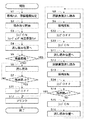
以上のように構成された画像読み取り装置が実行する動作処理を、以下、図11のフローチャートを用いて説明する。
【0069】
図11において、オペレータが原稿自動搬送装置200の原稿給紙トレイ9に原稿をセットし、図示しない操作部より原稿が両面原稿であるか片面原稿であるかを指定し(ステップS1)、スタートキー(図示せず)によりコピー動作をスタートさせると(ステップS2)、不図示のCPUは第1のミラーユニット208を基準白板5102の下に移動させ、1ライン分のシェーディング補正用データを読み取り、演算で求めたシェーディング補正係数をシェーディング補正回路4002内の係数メモリ4006にセットする(ステップS3)。
【0070】
次に、第1のミラーユニット208を流し読み原稿ガラス14の下に移動させる(ステップS4)。
【0071】
次に、原稿が両面原稿であるか片面原稿であるかを判断し(ステップS5)、原稿が片面原稿のときには、原稿自動搬送装置200の給紙ローラ8が原稿204上に下がり(図3(a))、原稿204の最上紙がピックアップされ、原稿204は搬送ローラ6の回転によりレジストローラ下3およびレジストローラ上4に搬送される。レジストローラ下3およびレジストローラ上4ではシートにループが形成され、シートの斜行が補正される(図3(b))。
【0072】
次に、原稿204はローラ2により搬送ローラ大1に押しつけられ、搬送ローラ大1の回転に応じて搬送され、リードコロ小13により原稿204が搬送ローラ大1から離れることを防止する(図3(c))。
【0073】
次に、原稿204は流し読み原稿読み取りガラス14上に搬送され、原稿画像の流し読み動作がなされ、原稿204は、リードコロ大12により搬送ローラ大1からの分離を防止しながら、排紙ローラ上11および排紙ローラ下10に搬送される(図3(d))。そして、原稿204は排紙ローラ上11および排紙ローラ下10により排紙トレイ15に排紙される(図3(e))。
【0074】
このとき、CPUはステップ3で得られたシェーディング補正係数に基づき原稿画像データを1ライン毎に補正しながら、原稿画像データをメモリ4009に読み込ませる(ステップS6)。
【0075】
次に、原稿自動搬送装置200に載置された原稿がなくなるまで原稿の流し読み動作(ステップS7,S6)を繰り返し(ステップS8)、原稿がなくなった時点でメモリ4009から画像データを読み出し、プリンタ部202によりコピー画像を形成し(ステップS17)、コピー動作を終了する。
【0076】
一方、原稿が両面画像の場合には、原稿自動搬送装置200での流し読み動作を行い、ステップ3で得られたシェーディング補正係数に基づき原稿表面画像データを1ライン毎に補正しながら、原稿画像データをメモリ4009に読み込ませる(ステップS8)。
【0077】
次に、原稿の裏面を読み取るために原稿の反転動作を行う(ステップ9)。排紙ローラ上11および排紙ローラ下10により排紙トレイ15上に一旦搬送された原稿204は(図3(e))、排紙ローラ上11および排紙ローラ下10を逆回転させることにより反転された状態でローラ2まで搬送される(図3(f))。ここで、ローラ2では、再びループが形成されシートの斜行が補正される(図3(g))。
【0078】
次に、原稿204は、ローラ2により搬送ローラ大1に押しつけられ、搬送ローラ大1の回転に応じて搬送され、リードコロ小13により原稿204が搬送ローラ大1から離れることを防止する(図3(h))。
【0079】
原稿反転時に、CPUは、第1のミラーユニット208を基準白板5102の下に移動させ、1ライン分のシェーディング補正用データを読み取り、演算で求めたシェーディング補正係数をシェーディング補正回路4002内の係数メモリ4006にセットした(ステップS10)後、第1のミラーユニット208を流し読み原稿ガラス14の下に移動させる(ステップS11)。
【0080】
次に、原稿204は流し読み原稿読み取りガラス14上に搬送され、原稿画像の流し読み動作がなされ、原稿204は、リードコロ大12により搬送ローラ大1からの分離を防止しながら、排紙ローラ上11および排紙ローラ下10に搬送される(図3(i))。そして、原稿204は、排紙ローラ上11および排紙ローラ下10により排紙トレイ15に排紙される(図3(j))。
【0081】
このとき、CPUは、ステップS10で得られたシェーディング補正係数に基づいて、原稿裏面画像データを1ライン毎に補正しながら、原稿画像データをメモリ4009に読み込ませる(ステップS12)。
【0082】
この時点で、原稿は原稿給紙トレイ9に載置された状態と裏返した状態になっているため、排紙された原稿が原稿給紙トレイ9に載置されたときと同じ向きとなるように、更に原稿を反転させるために、排紙ローラ上11および排紙ローラ下10を逆回転させることにより、原稿204は、反転された状態でローラ2まで搬送される(ステップS13、図3(k))。ローラ2では、再びループが形成されシートの斜行が補正される(図3(l))。
【0083】
次に、原稿204は、ローラ2により搬送ローラ大1に押しつけられ、搬送ローラ大1の回転に応じて搬送され、リードコロ小13により原稿204が搬送ローラ大1から離れることを防止する(図3(m))。そして、原稿204は、流し読み原稿読み取りガラス14上に搬送され、リードコロ大12により搬送ローラ大1からの分離を防止しながら、排紙ローラ上11および排紙ローラ下10に搬送され(図3(n))、排紙ローラ上11および排紙ローラ下10により排紙トレイ15に排紙される(図3(o))。
【0084】
原稿を裏面から表面に戻すときに、CPUは、原稿自動搬送装置200に載置された原稿が残っているかどうかの判定を行い(ステップS14)、原稿が残っている場合には、原稿反転時に第1のミラーユニット208を基準白板5102の下に移動させ、1ライン分のシェーディング補正用データを読み取り、演算で求めたシェーディング補正係数をシェーディング補正回路4002内の係数メモリ4006にセットした(ステップS15)後、第1のミラーユニット208を流し読み原稿ガラス14の下に移動させ(ステップS16)、次の原稿の読み取りを実施する。
【0085】
以降、原稿がなくなるまで、ステップS8からステップS16までの処理を繰り返し、原稿がなくなった時点で、メモリ4009から画像データを読み出し、プリンタ部202によりコピー画像を形成し(ステップS17)、コピー動作を終了する。
【0086】
なお、本実施の形態では、全ての原稿画像データをメモリ4009に記憶させた後にプリント出力する方法について説明したが、原稿画像データをメモリ4009に読み込みながらプリント出力する方法を採用してもよい。
【0087】
また、本実施の形態では、原稿が片面原稿の場合には、1枚目の原稿読み取りの前にだけ、シェーディング補正係数の更新を行ったが、読み取り画像に不具合が出る場合には、原稿の複数枚毎にシェーディング補正係数の更新を行うことも可能である。
【0088】
(第2の実施の形態)
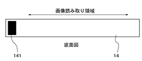
上記第1の実施の形態では、片面原稿の流し読みを行うときには、1枚目の原稿読み取りの前に基準白板5102を読み取った画像データを基に演算して得られたシェーディング補正係数によって、全原稿のシェーディング補正を行ったが、流し読み原稿読み取りガラス14の端部に貼付された光量基準白板141(図4参照)を読み取って得られたデータに応じて、シェーディング補正係数をリアルタイムで補正する公知の流し読み時のシェーディング補正方法を用いてもよい。例えば、連続原稿搬送中の紙間で光量基準白板141を読み取って得られるデータが2%低下したときには、原稿の読み取り画像信号のレベルが2%増加するように、補正係数をリアルタイムで変更して、キセノン管ランプ205の光量変動を補正する方法を用いてもよい。
【0089】
図12は、片面原稿を流し読みで読み取る場合に、原稿の紙間でシェーディング補正係数をリアルタイムで補正するときの動作を説明するフローチャート図である。本実施の形態は、上記第1の実施の形態とは、原稿が片面原稿の時の処理が異なるだけなので、片面原稿の処理についてのみ説明する。
【0090】
図12において、オペレータが原稿自動搬送装置200の原稿給紙トレイ9に原稿をセットし、図示しない操作部より原稿が両面原稿であるか片面原稿であるかを指定し(ステップS1)、スタートキー(図示せず)によりコピー動作をスタートさせると(ステップS2)、不図示のCPUは第1のミラーユニット208を基準白板5102の下に移動させ、1ライン分のシェーディング補正用データを読み取り、演算で求めたシェーディング補正係数をシェーディング補正回路4002内の係数メモリ4006にセットする(ステップS3)。
【0091】
次に、第1のミラーユニット208を流し読み原稿ガラス14の下に移動させる(ステップS4)。
【0092】
次に、原稿が両面原稿であるか片面原稿であるかを判断し(ステップS5)、原稿が片面原稿のときには、原稿自動搬送装置200の給紙ローラ8が原稿204上に下がり(図3(a))、原稿204の最上紙がピックアップされ、原稿204は搬送ローラ6の回転によりレジストローラ下3およびレジストローラ上4に搬送される。レジストローラ下3およびレジストローラ上4ではシートにループが形成され、シートの斜行が補正される(図3(b))。
【0093】
次に、原稿204はローラ2により搬送ローラ大1に押しつけられ、搬送ローラ大1の回転に応じて搬送され、リードコロ小13により原稿204が搬送ローラ大1から離れることを防止する(図3(c))。
【0094】
次に、原稿204は流し読み原稿読み取りガラス14上に搬送され、原稿画像の流し読み動作がなされ、原稿204は、リードコロ大12により搬送ローラ大1からの分離を防止しながら、排紙ローラ上11および排紙ローラ下10に搬送される(図3(d))。そして、原稿204は排紙ローラ上11および排紙ローラ下10により排紙トレイ15に排紙される(図3(e))。
【0095】
このとき、CPUはステップ3で得られたシェーディング補正係数に基づき原稿画像データを1ライン毎に補正しながら、原稿画像データをメモリ4009に読み込ませる(ステップS6)。
【0096】
次に、原稿自動搬送装置200に次に読み取る原稿があるかないかの判定を行い(ステップS7)、次に読み込む原稿がある場合には、流し読み原稿読み取りガラス14の端部に貼付された光量基準白板141を読み取って得られたデータに応じて、シェーディング補正係数をリアルタイムで補正する(ステップS21)。例えば、連続原稿搬送中の紙間で光量基準白板141を読み取って得られるデータが2%低下したときには、原稿の読み取り画像信号のレベルが2%増加するように、補正係数をリアルタイムで変更して、キセノン管ランプ205の光量変動を補正する。
【0097】
次に、ステップS18で補正されたシェーディング補正係数に基づいて、原稿画像データを1ライン毎に補正しながら、原稿画像データをメモリ4009に読み込ませる(ステップS6)。
【0098】
以下、載置された原稿がなくなるまで、原稿の流し読み動作(ステップS7,S21,S6)を繰り返し、原稿がなくなった時点で、メモリ4009から画像データを読み出し、プリンタ部202によりコピー画像を形成し(ステップS17)、コピー動作を終了する。
【0099】
なお、本実施の形態では、原稿が両面原稿であるか片面原稿であるかをオペレータが指定する方法を用いたが、これに限らず、画像読み取り装置が自動で判別するようにしてもよい。
【0100】
(第3の実施の形態)
図13は、本発明の第3の実施の形態に係る画像読み取り装置が実行する動作処理の手順を示すフローチャートである。
【0101】
図13において、オペレータが原稿自動搬送装置200の原稿給紙トレイ9に原稿をセットし、図示しない操作部より原稿が両面原稿であるか片面原稿であるかを指定し(ステップS1)、スタートキー(図示せず)によりコピー動作をスタートさせると(ステップS2)、不図示のCPUは第1のミラーユニット208を基準白板5102の下に移動させキセノン管ランプ205を点灯させ、1ライン分のシェーディング補正用データを読み取り、演算で求めたシェーディング補正係数をシェーディング補正回路4002内の係数メモリ4006にセットする(ステップS3)。
【0102】
次に、第1のミラーユニット208を流し読み原稿ガラス14の下に移動させる(ステップS4)。
【0103】
次に、原稿が両面原稿であるか片面原稿であるかを判断し(ステップS5)、原稿が片面原稿のときには、原稿自動搬送装置200の給紙ローラ8が原稿204上に下がり(図3(a))、原稿204の最上紙がピックアップされ、原稿204は搬送ローラ6の回転によりレジストローラ下3およびレジストローラ上4に搬送される。レジストローラ下3およびレジストローラ上4ではシートにループが形成され、シートの斜行が補正される(図3(b))。
【0104】
次に、原稿204はローラ2により搬送ローラ大1に押しつけられ、搬送ローラ大1の回転に応じて搬送され、リードコロ小13により原稿204が搬送ローラ大1から離れることを防止する(図3(c))。
【0105】
次に、原稿204は流し読み原稿読み取りガラス14上に搬送され、原稿画像の流し読み動作がなされ、原稿204は、リードコロ大12により搬送ローラ大1からの分離を防止しながら、排紙ローラ上11および排紙ローラ下10に搬送される(図3(d))。そして、原稿204は排紙ローラ上11および排紙ローラ下10により排紙トレイ15に排紙される(図3(e))。
【0106】
このとき、CPUは、ステップS3で得られたシェーディング補正係数に基づいて、原稿画像データを1ライン毎に補正しながら、原稿画像データをメモリ4009に読み込ませる(ステップS6)。
【0107】
次に、原稿自動搬送装置200に載置された原稿がなくなるまで原稿の流し読み動作(ステップS7,S6)を繰り返し、原稿がなくなった時点でキセノン管ランプ205を消灯させ(ステップS31)、メモリ4009から画像データを読み出し、プリンタ部202によりコピー画像を形成し(ステップS17)、コピー動作を終了する。
【0108】
一方、原稿が両面画像の場合には、原稿自動搬送装置200での流し読み動作を行い、ステップS3で得られたシェーディング補正係数に基づき原稿表面画像データを1ライン毎に補正しながら、原稿画像データをメモリ4009に読み込ませる(ステップS8)。
【0109】
次に、原稿の裏面を読み取るために原稿の反転動作を行う(ステップS9)と同時にキセノン管ランプ205を消灯させる(ステップS32)。排紙ローラ上11および排紙ローラ下10により排紙トレイ15上に一旦搬送された原稿204は(図3(e))、排紙ローラ上11および排紙ローラ下10を逆回転させることにより反転された状態でローラ2まで搬送される(図3(f))。ここで、ローラ2では、再びループが形成されシートの斜行が補正される(図3(g))。
【0110】
次に、原稿204は、ローラ2により搬送ローラ大1に押しつけられ、搬送ローラ大1の回転に応じて搬送され、リードコロ小13により原稿204が搬送ローラ大1から離れることを防止する(図3(h))。
【0111】
次に、反転した原稿204が読み取り位置の直前に到達したときにキセノン管ランプ205を点灯させ(ステップS33)、原稿204が流し読み原稿読み取りガラス14上に搬送され(ステップS11)、原稿画像の流し読み動作が行われ、続いて原稿204は、リードコロ大12により搬送ローラ大1からの分離を防止しながら、排紙ローラ上11および排紙ローラ下10に搬送される(図3(i))。そして、原稿204は、排紙ローラ上11および排紙ローラ下10により排紙トレイ15に排紙される(図3(j))。
【0112】
このとき、CPUは、ステップS3で得られたシェーディング補正係数に基づいて、原稿裏面画像データを1ライン毎に補正しながら、原稿画像データをメモリ4009に読み込ませる(ステップS12)。
【0113】
この時点で、原稿は原稿給紙トレイ9に載置された状態と裏返した状態になっているため、排紙された原稿が原稿給紙トレイ9に載置されたときと同じ向きとなるように、更に原稿を反転させる(ステップS13)と同時にキセノン管ランプ205を消灯させる(ステップS34)。原稿204は、排紙ローラ上11および排紙ローラ下10を逆回転させることにより反転された状態でローラ2まで搬送される(図3(k))。ローラ2では、再びループが形成されシートの斜行が補正される(図3(l))。
【0114】
次に、原稿204は、ローラ2により搬送ローラ大1に押しつけられ、搬送ローラ大1の回転に応じて搬送され、リードコロ小13により原稿204が搬送ローラ大1から離れることを防止する(図3(m))。そして、原稿204は、流し読み原稿読み取りガラス14上に搬送され、リードコロ大12により搬送ローラ大1からの分離を防止しながら、排紙ローラ上11および排紙ローラ下10に搬送され(図3(n))、排紙ローラ上11および排紙ローラ下10により排紙トレイ15に排紙される(図3(o))。
【0115】
原稿を裏面から表面に戻すときに、CPUは、原稿自動搬送装置200に載置された原稿が残っているかどうかの判定を行い(ステップS14)、原稿が残っている場合には、次の原稿を原稿自動搬送装置200で読み取り位置へ搬送し、原稿204が読み取り位置の直前に到達したときにキセノン管ランプ205を点灯させる(ステップS35)。そして、原稿204が流し読み原稿読み取りガラス14上に搬送され(ステップS16)、以降、原稿がなくなるまで、ステップS8からステップS16までの処理を繰り返し、原稿がなくなった時点でメモリ4009から画像データを読み出し、プリンタ部202によりコピー画像を形成し(ステップS17)、コピー動作を終了する。
【0116】
なお、本実施の形態では、全ての原稿画像データをメモリ4009を記憶させた後にプリント出力する方法について説明したが、原稿画像データをメモリ4009に読み込みながらプリント出力する方法を採用してもよい。
【0117】
また、本実施の形態では、原稿が両面原稿であるか片面原稿であるかをオペレータが指定する方法を用いたが、これに限らず、画像読み取り装置が自動で判別するようにしてもよい。
【0118】
また、本実施の形態では片面原稿読み取り時には原稿を照射する光源を点灯し続ける方法について説明したが、光源の温度が所定値を越える場合や、光源の連続点灯時間が所定の時間以上に達した場合には、光源を消灯し、原稿の読み取り動作を一旦停止し、光源の温度が所定温度以下になったとき、または所定時間光源を消灯した後に原稿の読み取り動作を再開してもよい。
【0119】
なお、上述した各実施の形態の機能を実現するソフトウェアのプログラムコードを記録した記憶媒体を、システムまたは装置に供給し、そのシステムまたは装置のコンピュータ(またはCPUやMPU)が記憶媒体に格納されたプログラムコードを読出し実行することによっても、本発明の目的が達成されることは言うまでもない。
【0120】
この場合、記憶媒体から読出されたプログラムコード自体が本発明の新規な機能を実現することになり、そのプログラムコードを記憶した記憶媒体は本発明を構成することになる。
【0121】
プログラムコードを供給するための記憶媒体としては、たとえば、フロッピー(登録商標)ディスク、ハードディスク、光ディスク、光磁気ディスク、CD−ROM、CD−R、磁気テープ、不揮発性のメモリカード、ROMなどを用いることができる。また、通信ネットワークを介してサーバコンピュータからプログラムコードが供給されるようにしてもよい。
【0122】
また、コンピュータが読出したプログラムコードを実行することにより、上述した各実施の形態の機能が実現されるだけでなく、そのプログラムコードの指示に基づき、コンピュータ上で稼働しているOSなどが実際の処理の一部または全部を行い、その処理によって上述した実施の形態の機能が実現される場合も含まれることは言うまでもない。
【0123】
さらに、記憶媒体から読出されたプログラムコードが、コンピュータに挿入された機能拡張ボードやコンピュータに接続された機能拡張ユニットに備わるメモリに書込まれた後、そのプログラムコードの指示に基づき、その機能拡張ボードや機能拡張ユニットに備わるCPUなどが実際の処理の一部または全部を行い、その処理によって上述した各実施の形態の機能が実現される場合も含まれることは言うまでもない。
【0124】
以下、本発明の実施態様の例を列挙する。
【0125】
(実施態様1) 複数枚の原稿を連続転送可能で、かつ原稿を反転し、原稿の両面を読み取り可能にさせる原稿自動送り手段と、原稿を照明する照明手段と、原稿画像をライン毎に電気信号に変換する光電変換手段と、原稿の反射光を前記光電変換手段に結像する光学手段とを備え、原稿を前記原稿自動送り手段により搬送しながら読み取る画像読み取り装置において、
前記光電変換手段により基準白板を読み取って得られた読み取りデータに基づいてシェーディング補正係数を算出する算出手段と、
該算出手段によって算出されたシェーディング補正係数により、前記照明手段、前記光電変換手段および前記光学手段のうち少なくとも1つの不均一性を画素毎に補正するシェーディング補正手段と、
原稿が両面読み取りの場合には、該原稿が前記原稿自動送り手段によって反転されるときに、前記算出手段により新たにシェーディング補正係数を算出し、前記シェーディング補正手段が用いるシェーディング補正係数を、該新たなシェーディング補正係数で更新する更新手段と
を有することを特徴とする画像読み取り装置。
【0126】
(実施態様2) 複数枚の原稿を連続転送可能で、かつ原稿を反転し、原稿の両面を読み取り可能にさせる原稿自動送り手段と、原稿を照明する照明手段と、原稿画像をライン毎に電気信号に変換する光電変換手段と、原稿の反射光を前記光電変換手段に結像する光学手段とを備え、原稿を前記原稿自動送り手段により搬送しながら読み取る画像読み取り装置において、
前記光電変換手段により第1の基準白板を読み取って得られた読み取りデータに基づいてシェーディング補正係数を算出する算出手段と、
該算出手段によって算出されたシェーディング補正係数により、前記照明手段、前記光電変換手段および前記光学手段のうち少なくとも1つの不均一性を画素毎に補正するシェーディング補正手段と、
第2の基準白板の所定領域における画像読み取りデータに基づいて1ライン単位で前記照明手段および前記光学手段の少なくとも一方の変動を補正する光量変動補正手段と、
原稿が両面読み取りの場合と片面読み取りの場合とで、前記シェーディング補正手段と前記光量変動補正手段のいずれを採用するかを選択的に切り換える切り換え手段と
を有することを特徴とする画像読み取り装置。
【0127】
(実施態様3) 複数枚の原稿を連続転送可能で、かつ原稿を反転し、原稿の両面を読み取り可能にさせる原稿自動送り手段と、原稿を照明する照明手段と
を有し、原稿を前記原稿自動送り手段により搬送しながら読み取る画像読み取り装置において、
原稿が両面読み取りの場合には、該原稿が前記原稿自動送り手段によって反転されるときに、前記照明手段を消灯するように制御する制御手段
を有することを特徴とする画像読み取り装置。
【0128】
この実施態様3によれば、原稿自動搬送手段によって搬送する原稿が両面原稿の場合には、原稿の片面読み取り後に原稿を反転するタイミングで原稿を照射する光源が消灯されるので、光源の昇温をおさえ、画質劣化のない状態で両面原稿を複数枚短時間で読み取ることが可能となる。
【0129】
(実施態様4) 複数枚の原稿を連続転送可能で、かつ原稿を反転し、原稿の両面を読み取り可能にさせる原稿自動送り手段と、原稿を照明する照明手段と、原稿画像をライン毎に電気信号に変換する光電変換手段と、原稿の反射光を前記光電変換手段に結像する光学手段とを備え、原稿を前記原稿自動送り手段により搬送しながら読み取る画像読み取り装置を制御する制御方法において、
前記光電変換手段により基準白板を読み取って得られた読み取りデータに基づいてシェーディング補正係数を算出する算出ステップと、
該算出ステップによって算出されたシェーディング補正係数により、前記照明手段、前記光電変換手段および前記光学手段のうち少なくとも1つの不均一性を画素毎に補正するシェーディング補正ステップと、
原稿が両面読み取りの場合には、該原稿が前記原稿自動送り手段によって反転されるときに、前記算出ステップにより新たにシェーディング補正係数を算出し、前記シェーディング補正ステップが用いるシェーディング補正係数を、該新たなシェーディング補正係数で更新する更新ステップと
を有することを特徴とする画像読み取り装置の制御方法。
【0130】
(実施態様5) 複数枚の原稿を連続転送可能で、かつ原稿を反転し、原稿の両面を読み取り可能にさせる原稿自動送り手段と、原稿を照明する照明手段と、原稿画像をライン毎に電気信号に変換する光電変換手段と、原稿の反射光を前記光電変換手段に結像する光学手段とを備え、原稿を前記原稿自動送り手段により搬送しながら読み取る画像読み取り装置を制御する制御方法において、
前記光電変換手段により第1の基準白板を読み取って得られた読み取りデータに基づいてシェーディング補正係数を算出する算出ステップと、
該算出ステップによって算出されたシェーディング補正係数により、前記照明手段、前記光電変換手段および前記光学手段のうち少なくとも1つの不均一性を画素毎に補正するシェーディング補正ステップと、
第2の基準白板の所定領域における画像読み取りデータに基づいて1ライン単位で前記照明手段および前記光学手段の少なくとも一方の変動を補正する光量変動補正ステップと、
原稿が両面読み取りの場合と片面読み取りの場合とで、前記シェーディング補正ステップと前記光量変動補正ステップのいずれを採用するかを選択的に切り換える切り換えステップと
を有することを特徴とする画像読み取り装置の制御方法。
【0131】
(実施態様6) 複数枚の原稿を連続転送可能で、かつ原稿を反転し、原稿の両面を読み取り可能にさせる原稿自動送り手段と、原稿を照明する照明手段と
を有し、原稿を前記原稿自動送り手段により搬送しながら読み取る画像読み取り装置を制御する制御方法において、
原稿が両面読み取りの場合には、該原稿が前記原稿自動送り手段によって反転されるときに、前記照明手段を消灯する
ことを特徴とする画像読み取り装置の制御方法。
【0132】
(実施態様7) 複数枚の原稿を連続転送可能で、かつ原稿を反転し、原稿の両面を読み取り可能にさせる原稿自動送り手段と、原稿を照明する照明手段と、原稿画像をライン毎に電気信号に変換する光電変換手段と、原稿の反射光を前記光電変換手段に結像する光学手段とを備え、原稿を前記原稿自動送り手段により搬送しながら読み取る画像読み取り装置を制御する制御方法を実現するためのプログラムであって、
前記制御方法は、
前記光電変換手段により基準白板を読み取って得られた読み取りデータに基づいてシェーディング補正係数を算出する算出ステップと、
該算出ステップによって算出されたシェーディング補正係数により、前記照明手段、前記光電変換手段および前記光学手段のうち少なくとも1つの不均一性を画素毎に補正するシェーディング補正ステップと、
原稿が両面読み取りの場合には、該原稿が前記原稿自動送り手段によって反転されるときに、前記算出ステップにより新たにシェーディング補正係数を算出し、前記シェーディング補正ステップが用いるシェーディング補正係数を、該新たなシェーディング補正係数で更新する更新ステップと
を有する
ことを特徴とするプログラム。
【0133】
(実施態様8) 複数枚の原稿を連続転送可能で、かつ原稿を反転し、原稿の両面を読み取り可能にさせる原稿自動送り手段と、原稿を照明する照明手段と、原稿画像をライン毎に電気信号に変換する光電変換手段と、原稿の反射光を前記光電変換手段に結像する光学手段とを備え、原稿を前記原稿自動送り手段により搬送しながら読み取る画像読み取り装置を制御する制御方法を実現するためのプログラムであって、
前記制御方法は、
前記光電変換手段により第1の基準白板を読み取って得られた読み取りデータに基づいてシェーディング補正係数を算出する算出ステップと、
該算出ステップによって算出されたシェーディング補正係数により、前記照明手段、前記光電変換手段および前記光学手段のうち少なくとも1つの不均一性を画素毎に補正するシェーディング補正ステップと、
第2の基準白板の所定領域における画像読み取りデータに基づいて1ライン単位で前記照明手段および前記光学手段の少なくとも一方の変動を補正する光量変動補正ステップと、
原稿が両面読み取りの場合と片面読み取りの場合とで、前記シェーディング補正ステップと前記光量変動補正ステップのいずれを採用するかを選択的に切り換える切り換えステップと
を有する
ことを特徴とするプログラム。
【0134】
(実施態様9) 複数枚の原稿を連続転送可能で、かつ原稿を反転し、原稿の両面を読み取り可能にさせる原稿自動送り手段と、原稿を照明する照明手段と
を有し、原稿を前記原稿自動送り手段により搬送しながら読み取る画像読み取り装置を制御する制御方法を実現するためのプログラムであって、
前記制御方法は、
原稿が両面読み取りの場合には、該原稿が前記原稿自動送り手段によって反転されるときに、前記照明手段を消灯する
ことを特徴とするプログラム。
【0135】
【発明の効果】
以上説明したように、本発明によれば、原稿自動搬送手段によって搬送中の原稿が両面原稿の場合に、画質劣化のない状態で両面原稿を複数枚短時間で読み取ることが可能となる。
【図面の簡単な説明】
【図1】本発明の一実施の形態に係る画像読み取り装置の概略構成を示す断面図である。
【図2】図1の原稿自動搬送装置の構成を示す断面図である。
【図3】図2の原稿自動搬送装置によって原稿が送られる様子を説明するための図である。
【図4】本実施の形態の画像読み取り装置で用いられる流し読みガラスの底面図である。
【図5】本実施の形態の画像読み取り装置で用いられるCCDセンサの構成を示す図である。
【図6】図5のCCDセンサの受光素子の拡大図である。
【図7】本実施の形態の画像読み取り装置で用いられる信号処理部の構成を示すブロック図である。
【図8】本実施の形態の画像読み取り装置で用いられるアナログ信号処理部の構成を示すブロック図である。
【図9】PG画像の一例を示す図である。
【図10】階調補正の一手法を説明するための図である。
【図11】図1の画像読み取り装置が実行する動作処理の手順を示すフローチャートである。
【図12】本発明の第2の実施の形態に係る画像読み取り装置が実行する動作処理の手順を示すフローチャートである。
【図13】本発明の第3の実施の形態に係る画像読み取り装置が実行する動作処理の手順を示すフローチャートである。
【符号の説明】
1 搬送ローラ大
2 ローラ
3 レジストローラ下
4 レジストローラ上
6 搬送ローラ
8 給紙ローラ
9 原稿給紙トレイ
10 排紙ローラ下
11 排紙ローラ上
12 リードコロ大
13 リードコロ小
14 流し読み原稿読み取りガラス
200 原稿自動搬送装置
201 イメージスキャナ部
202 プリンタ部
203 原稿台ガラス
205 キセノン管ランプ
206,207 反射ミラー
2071 第2のミラーユニット
208 第1のミラーユニット
209 レンズ
210 3ラインセンサ
211 信号処理部
212 レーザドライバ
213 半導体レーザ
214 ポリゴンミラー
215 f−θレンズ
216 ミラー
217 感光ドラム
218 回転現像器
223 転写ドラム
224,225 用紙カセット
226 定着ユニット
5102 標準白色板[0001]
TECHNICAL FIELD OF THE INVENTION
The present invention includes an automatic document feeder capable of continuously transferring a plurality of documents, inverting the document, and enabling both sides of the document to be read, and an image for reading an image of the document transported by the document automatic feeder. Related to a reading device.
[0002]
[Prior art]
2. Description of the Related Art Conventionally, a copying machine has been known as an image reading apparatus that includes an automatic document feeder and reads an image of a document transported by the automatic document feeder.
[0003]
In such a copying machine, an image of an original is read by moving and placing the original on an original platen glass of a reading device by an automatic original transporter, and then moving a mirror unit equipped with an illumination light source onto the original platen glass. Was like that.
[0004]
However, recently, in order to increase the number of documents read per unit time, a so-called drift reading method has been adopted, in which a mirror unit is fixed at a predetermined position, and a document image is read while the document is being sent to the reading device by an automatic document feeder. It is getting.
[0005]
FIG. 1 is a cross-sectional view showing the configuration of a color copying machine employing such a flow reading system.
[0006]
Referring to FIG. 1, the color copying machine mainly includes an
[0007]
The automatic document feeder 200 feeds a document to the
[0008]
The
[0009]
Further, the
[0010]
In the
[0011]
The signal processing unit 211 performs predetermined signal processing on the transmitted electric signals and outputs the processed signals to the
[0012]
The
[0013]
In the case where the original is read by the
[0014]
FIG. 2 is a cross-sectional view showing the configuration of the
[0015]
3, when the original 204 is placed on the
[0016]
Next, the
[0017]
Next, the original 204 is conveyed onto the flow-reading
[0018]
Next, the
[0019]
Next, the
[0020]
At this point, the original is placed on the
[0021]
Next, the
[0022]
When reading a plurality of originals, the operations (a) to (o) are repeated until the originals placed on the
[0023]
Here, the
[0024]
The transport roller large 1 is pressed against the flow-reading
[0025]
Here, the case where one document is read has been described. However, when reading a plurality of documents continuously, the same operation is continuously repeated with a predetermined interval between each document conveyance.
[0026]
Also, when the original is read by the flowing reading method, the original is continuously read in a short time, so that the reading of the standard white plate for the well-known shading correction is performed only before reading the first original, Until the
[0027]
Further, in order to increase the number of originals that can be read per unit time, the speed at which the original is scanned by a CCD (Charged Coupled Device) line sensor or the like is increased. In the CCD line sensor, since the speed of scanning the document and the output signal level are inversely proportional, it is necessary to increase the light amount of the light source for irradiating the document in order to prevent the image quality from deteriorating even if the document reading speed is increased.
[0028]
[Problems to be solved by the invention]
However, when reading a two-sided original in the above-described conventional image reading apparatus, the operation of inverting the original for one original is required twice as described above. When many documents are scanned, the time required to read all the documents becomes very long, and the fluctuation of the light amount of the light source illuminating the documents becomes a non-negligible level, deteriorating the image quality of the scanned documents. There was a disadvantage that it would.
[0029]
Furthermore, in order to increase the number of screen documents read per unit time without deteriorating the image quality, the amount of light of the light source for irradiating the document must be increased. However, there is a drawback that the emission spectrum of the CCD line sensor fluctuates, the temperature of the entire apparatus rises, and the sensitivity characteristic of the CCD line sensor fluctuates.
[0030]
The present invention has been made in view of these points, and an object of the present invention is to provide an image reading apparatus capable of reading a plurality of double-sided originals in a short time without deterioration in image quality.
[0031]
[Means for Solving the Problems]
In order to achieve the above object, according to the present invention, an automatic document feeder for continuously transferring a plurality of documents, inverting the documents, and enabling both sides of the documents to be read, and illuminating the documents. Illuminating means, photoelectric conversion means for converting a document image into an electric signal for each line, and optical means for forming reflected light of the document on the photoelectric conversion means, wherein the document is transported by the document automatic feeding means. In the image reading device to be read, a calculating means for calculating a shading correction coefficient based on read data obtained by reading a reference white board by the photoelectric conversion means, and the shading correction coefficient calculated by the calculating means, the lighting means, A shading correction unit for correcting non-uniformity of at least one of the photoelectric conversion unit and the optical unit for each pixel; In the case of double-sided reading, when the document is inverted by the document automatic feeding means, a new shading correction coefficient is calculated by the calculation means, and the shading correction coefficient used by the shading correction means is replaced by the new shading correction coefficient. Updating means for updating with a correction coefficient.
[0032]
BEST MODE FOR CARRYING OUT THE INVENTION
Hereinafter, embodiments of the present invention will be described in detail with reference to the drawings.
[0033]
In the present embodiment, a copying machine is shown as an application example of the present invention. However, the present invention is not limited to this, and it goes without saying that the present invention can be applied to various other apparatuses.
[0034]
(First Embodiment)
FIG. 1 is a cross-sectional view illustrating a schematic configuration of an image reading apparatus according to a first embodiment of the present invention. As described above, the present invention is applied to a color copying machine.
[0035]
In FIG. 1, the image reading apparatus according to the present embodiment mainly includes an
[0036]
The
[0037]
The
[0038]
Further, the
[0039]
In the
[0040]
The signal processing unit 211 performs predetermined signal processing on the transmitted electric signals and outputs the processed signals to the
[0041]
The
[0042]
The standard
[0043]
In the case where the original is read by the
[0044]
The signal processing unit 211 converts the image signal read by the three-
[0045]
Each image signal of M, C, Y, and BK transmitted from the
[0046]
The
[0047]
The
[0048]
After the four colors of M, C, Y, and BK are sequentially transferred in this manner, the sheet passes through the fixing
[0049]
FIG. 5 is a diagram showing an example of the configuration of the three-
[0050]
In the figure, light receiving element arrays 210-1, 210-2, and 210-3 are for reading R, G, and B wavelength components, respectively.
[0051]
The three light receiving element arrays having different optical characteristics are monolithically formed on the same silicon chip so that the R, G, and B sensors are arranged in parallel with each other to read the same line of the document. I have.
[0052]
FIG. 6 is an enlarged view of the light receiving element row in FIG. 5 described above.
[0053]
As shown in the figure, each of the sensors 210-1 to 210-3 has a width of, for example, 10 μm per pixel in the main scanning direction. Each of the sensors 210-1 to 210-3 has 5000 pixels in the main scanning direction so that the short direction (297 mm) of an A3 document can be read at a resolution of 400 dpi. The distance between the lines of the R, G, and B sensors 210-1 to 210-3 is, for example, 80 μm, and each line is separated by eight lines for a sub-scanning resolution of 400 lpi. Further, in each of the line sensors 210-1 to 210-3, an optical filter is formed on the sensor surface in order to obtain predetermined spectral characteristics of R, G, and B.
[0054]
FIG. 7 is a block diagram illustrating a configuration of the
[0055]
In the figure, an image signal output from a
[0056]
FIG. 8 is a block diagram illustrating a configuration of the analog
[0057]
In the figure, an image signal output from the
[0058]
Returning to FIG. 7, the 8-bit digital image signal is subjected to shading correction by a known shading correction method in a shading correction unit 4002. When reading shading data, the CPU stores a read signal for one line from the standard
[0059]
Next, correction of the physical distance of the three-
[0060]
As shown in FIG. 6, since the light receiving sections 210-1, 210-2, and 210-3 of the
[0061]
A first look-up table (hereinafter, referred to as “LUT”) 4008 is for correcting the gradation of a document image reading signal. A document on which an image having a predetermined density shown in FIG. 9 is drawn is placed on the
[0062]
The
[0063]
The
[0064]
The
[0065]
A PG image based on the PG data output from the
[0066]
The masking and
[0067]
Each of the above circuits is controlled by a CPU (not shown).
[0068]
The operation processing executed by the image reading apparatus configured as described above will be described below with reference to the flowchart of FIG.
[0069]
In FIG. 11, the operator sets a document on the
[0070]
Next, the
[0071]
Next, it is determined whether the original is a two-sided original or a one-sided original (step S5). If the original is a one-sided original, the
[0072]
Next, the
[0073]
Next, the original 204 is conveyed onto the
[0074]
At this time, the CPU reads the document image data into the
[0075]
Next, the document flow reading operation (Steps S7 and S6) is repeated (Step S8) until there are no more documents placed on the
[0076]
On the other hand, when the original is a two-sided image, the original reading operation is performed in the automatic
[0077]
Next, a reverse operation of the original is performed to read the back side of the original (step 9). The original 204 once conveyed onto the
[0078]
Next, the
[0079]
At the time of document reversal, the CPU moves the
[0080]
Next, the original 204 is conveyed onto the
[0081]
At this time, the CPU causes the
[0082]
At this point, the original is placed on the
[0083]
Next, the
[0084]
When returning the original from the back to the front, the CPU determines whether or not the original placed on the
[0085]
Thereafter, the processing from step S8 to step S16 is repeated until there is no document, and when there is no document, the image data is read from the
[0086]
Note that, in the present embodiment, a method has been described in which all document image data is stored in the
[0087]
Further, in the present embodiment, when the original is a one-sided original, the shading correction coefficient is updated only before reading the first original. It is also possible to update the shading correction coefficient for each sheet.
[0088]
(Second embodiment)
In the first embodiment, when a single-sided original is to be scanned, a total shading correction coefficient obtained by calculating based on image data obtained by reading the reference
[0089]
FIG. 12 is a flowchart for explaining the operation when the shading correction coefficient is corrected in real time between the sheets of the original in the case where the one-sided original is scanned and read. This embodiment is different from the first embodiment only in the processing when the original is a one-sided original, so only the processing for a one-sided original will be described.
[0090]
In FIG. 12, the operator sets a document on the
[0091]
Next, the
[0092]
Next, it is determined whether the original is a two-sided original or a one-sided original (step S5). If the original is a one-sided original, the
[0093]
Next, the
[0094]
Next, the original 204 is conveyed onto the
[0095]
At this time, the CPU reads the document image data into the
[0096]
Next, it is determined whether or not there is a next document to be read in the automatic document feeder 200 (step S7). If there is a next document to be read, the light amount affixed to the end of the flow reading
[0097]
Next, the original image data is read into the
[0098]
Thereafter, the flow reading operation of the originals (steps S7, S21, S6) is repeated until there are no more originals, and when there are no more originals, the image data is read from the
[0099]
In the present embodiment, a method is used in which the operator specifies whether the original is a double-sided original or a single-sided original. However, the present invention is not limited to this, and the image reading device may automatically determine the original.
[0100]
(Third embodiment)
FIG. 13 is a flowchart illustrating a procedure of an operation process executed by the image reading apparatus according to the third embodiment of the present invention.
[0101]
In FIG. 13, an operator sets a document on the
[0102]
Next, the
[0103]
Next, it is determined whether the original is a two-sided original or a one-sided original (step S5). If the original is a one-sided original, the
[0104]
Next, the
[0105]
Next, the original 204 is conveyed onto the
[0106]
At this time, the CPU reads the document image data into the
[0107]
Next, the document flow reading operation (steps S7 and S6) is repeated until there are no more documents placed on the
[0108]
On the other hand, if the original is a double-sided image, the automatic
[0109]
Next, the
[0110]
Next, the
[0111]
Next, when the
[0112]
At this time, the CPU reads the document image data into the
[0113]
At this point, the original is placed on the
[0114]
Next, the
[0115]
When returning the original from the back to the front, the CPU determines whether or not the original placed on the
[0116]
In the present embodiment, a method has been described in which all the document image data is printed out after being stored in the
[0117]
Further, in the present embodiment, a method is used in which the operator designates whether the original is a double-sided original or a single-sided original. However, the present invention is not limited to this, and the image reading device may automatically determine the original.
[0118]
Further, in the present embodiment, the method of continuously lighting the light source that irradiates the original when reading the one-sided original has been described. In this case, the light source may be turned off, the reading operation of the document may be temporarily stopped, and the reading operation of the document may be restarted when the temperature of the light source becomes lower than a predetermined temperature or after the light source is turned off for a predetermined time.
[0119]
A storage medium storing the program code of software for realizing the functions of the above-described embodiments is supplied to a system or an apparatus, and a computer (or CPU or MPU) of the system or the apparatus is stored in the storage medium. It goes without saying that the object of the present invention is also achieved by reading and executing the program code.
[0120]
In this case, the program code itself read from the storage medium implements the novel function of the present invention, and the storage medium storing the program code constitutes the present invention.
[0121]
As a storage medium for supplying the program code, for example, a floppy (registered trademark) disk, hard disk, optical disk, magneto-optical disk, CD-ROM, CD-R, magnetic tape, nonvolatile memory card, ROM, or the like is used. be able to. Further, the program code may be supplied from a server computer via a communication network.
[0122]
When the computer executes the readout program code, not only the functions of each of the above-described embodiments are realized, but also an OS or the like running on the computer is actually executed based on the instructions of the program code. It goes without saying that a part or all of the processing is performed, and the functions of the above-described embodiments are realized by the processing.
[0123]
Further, after the program code read from the storage medium is written into a memory provided in a function expansion board inserted into the computer or a function expansion unit connected to the computer, the function expansion is performed based on the instruction of the program code. It goes without saying that a CPU or the like provided in the board or the function expansion unit performs part or all of the actual processing, and the processing realizes the functions of the above-described embodiments.
[0124]
Hereinafter, examples of embodiments of the present invention will be listed.
[0125]
(Embodiment 1) Automatic document feeding means for continuously transferring a plurality of documents, reversing the document, and enabling both sides of the document to be readable, illuminating means for illuminating the document, and electrically connecting the document image line by line A photoelectric conversion unit for converting a signal into a signal, and an optical unit for forming an image of the reflected light of the original on the photoelectric conversion unit, and an image reading apparatus for reading the original while transporting the original by the automatic original feeding unit,
Calculation means for calculating a shading correction coefficient based on read data obtained by reading a reference white board by the photoelectric conversion means,
A shading correction unit that corrects non-uniformity of at least one of the illumination unit, the photoelectric conversion unit, and the optical unit for each pixel by a shading correction coefficient calculated by the calculation unit;
In the case where the document is read on both sides, when the document is inverted by the document automatic feeding means, a new shading correction coefficient is calculated by the calculation means, and the shading correction coefficient used by the shading correction means is replaced with the new shading correction coefficient. Update means for updating with various shading correction coefficients
An image reading device comprising:
[0126]
(Embodiment 2) Automatic document feeding means for continuously transferring a plurality of documents, reversing the document and enabling reading of both sides of the document, illuminating means for illuminating the document, and electrically connecting the document image line by line A photoelectric conversion unit for converting a signal into a signal, and an optical unit for forming an image of the reflected light of the original on the photoelectric conversion unit, and an image reading apparatus for reading the original while transporting the original by the automatic original feeding unit,
Calculating means for calculating a shading correction coefficient based on read data obtained by reading the first reference white board by the photoelectric conversion means;
A shading correction unit that corrects non-uniformity of at least one of the illumination unit, the photoelectric conversion unit, and the optical unit for each pixel by a shading correction coefficient calculated by the calculation unit;
A light amount fluctuation correction unit that corrects a fluctuation of at least one of the illumination unit and the optical unit on a line-by-line basis based on image reading data in a predetermined region of the second reference white plate;
Switching means for selectively switching which of the shading correction means and the light quantity fluctuation correction means is to be used when the original is read on both sides and when the original is read on one side.
An image reading device comprising:
[0127]
(Embodiment 3) Automatic document feeding means capable of continuously transferring a plurality of documents, inverting the document, and enabling reading of both sides of the document, and illuminating means for illuminating the document
An image reading apparatus that has an original reading unit that reads an original while transporting the original by the original automatic feeding unit,
Control means for controlling to turn off the illuminating means when the original is inverted by the automatic document feeding means when the original is read on both sides;
An image reading device comprising:
[0128]
According to the third embodiment, when the original conveyed by the automatic original conveyance means is a double-sided original, the light source for irradiating the original is turned off at the timing of inverting the original after reading the one side of the original. Therefore, it is possible to read a plurality of double-sided originals in a short time without deterioration in image quality.
[0129]
(Embodiment 4) Automatic document feeding means for continuously transferring a plurality of documents, reversing the document and enabling reading of both sides of the document, illuminating means for illuminating the document, and electrically connecting the document image line by line. A control method for controlling an image reading device that includes a photoelectric conversion unit that converts a signal into a signal, and an optical unit that forms an image of reflected light of the original on the photoelectric conversion unit, and reads the original while conveying the original by the automatic original feeding unit,
A calculating step of calculating a shading correction coefficient based on read data obtained by reading a reference white board by the photoelectric conversion unit,
A shading correction step of correcting, for each pixel, non-uniformity of at least one of the illumination unit, the photoelectric conversion unit, and the optical unit, by a shading correction coefficient calculated by the calculation step;
When the document is read on both sides, when the document is inverted by the document automatic feeding means, a new shading correction coefficient is calculated in the calculation step, and the shading correction coefficient used in the shading correction step is replaced with the new shading correction coefficient. Update step with the appropriate shading correction coefficient
A method for controlling an image reading apparatus, comprising:
[0130]
(Embodiment 5) Automatic document feeding means for continuously transferring a plurality of documents, inverting the document, and enabling both sides of the document to be readable, illuminating means for illuminating the document, and electrically connecting the document image line by line. A control method for controlling an image reading device that includes a photoelectric conversion unit that converts a signal into a signal, and an optical unit that forms an image of reflected light of the original on the photoelectric conversion unit, and reads the original while conveying the original by the automatic original feeding unit,
A calculating step of calculating a shading correction coefficient based on read data obtained by reading the first reference white board by the photoelectric conversion means;
A shading correction step of correcting, for each pixel, non-uniformity of at least one of the illumination unit, the photoelectric conversion unit, and the optical unit, by a shading correction coefficient calculated by the calculation step;
A light amount fluctuation correction step of correcting a fluctuation of at least one of the illumination unit and the optical unit on a line-by-line basis based on image reading data in a predetermined region of the second reference white plate;
A switching step for selectively switching between the shading correction step and the light amount fluctuation correction step depending on whether the original is a two-sided reading or a one-sided reading.
A method for controlling an image reading apparatus, comprising:
[0131]
(Embodiment 6) Automatic document feeding means for continuously transferring a plurality of documents, reversing the document, and enabling reading of both sides of the document, and illuminating means for illuminating the document
A control method for controlling an image reading apparatus that reads an original while transporting the original by the automatic document feeder,
When the document is read on both sides, the illumination unit is turned off when the document is inverted by the document automatic feeding unit.
A method for controlling an image reading apparatus, comprising:
[0132]
(Embodiment 7) Automatic document feeding means for continuously transferring a plurality of documents, reversing the document and enabling reading of both sides of the document, lighting means for illuminating the document, and electrically connecting the document image line by line. A control method for controlling an image reading apparatus comprising: a photoelectric conversion unit for converting a signal into a signal; and an optical unit for forming an image of reflected light of the original on the photoelectric conversion unit, and reading the original while conveying the original by the automatic original feeding unit. A program for
The control method includes:
A calculating step of calculating a shading correction coefficient based on read data obtained by reading a reference white board by the photoelectric conversion unit,
A shading correction step of correcting, for each pixel, non-uniformity of at least one of the illumination unit, the photoelectric conversion unit, and the optical unit, by a shading correction coefficient calculated by the calculation step;
When the document is read on both sides, when the document is inverted by the document automatic feeding means, a new shading correction coefficient is calculated in the calculation step, and the shading correction coefficient used in the shading correction step is replaced with the new shading correction coefficient. Update step with the appropriate shading correction coefficient
Having
A program characterized by the following.
[0133]
(Embodiment 8) Automatic document feeding means for continuously transferring a plurality of documents, reversing the document and enabling reading of both sides of the document, illuminating means for illuminating the document, and electrically connecting the document image line by line. A control method for controlling an image reading apparatus comprising: a photoelectric conversion unit for converting a signal into a signal; and an optical unit for forming an image of reflected light of the original on the photoelectric conversion unit, and reading the original while conveying the original by the automatic original feeding unit. A program for
The control method includes:
A calculating step of calculating a shading correction coefficient based on read data obtained by reading the first reference white board by the photoelectric conversion means;
A shading correction step of correcting, for each pixel, non-uniformity of at least one of the illumination unit, the photoelectric conversion unit, and the optical unit, by a shading correction coefficient calculated by the calculation step;
A light amount fluctuation correction step of correcting a fluctuation of at least one of the illumination unit and the optical unit on a line-by-line basis based on image reading data in a predetermined region of the second reference white plate;
A switching step for selectively switching between the shading correction step and the light amount fluctuation correction step depending on whether the original is a two-sided reading or a one-sided reading.
Having
A program characterized by the following.
[0134]
(Embodiment 9) Automatic document feeding means for continuously transferring a plurality of documents, reversing the document, and enabling reading of both sides of the document, and illuminating means for illuminating the document
A program for realizing a control method for controlling an image reading apparatus that reads a document while transporting the document by the automatic document feeder,
The control method includes:
When the document is read on both sides, the illumination unit is turned off when the document is inverted by the document automatic feeding unit.
A program characterized by the following.
[0135]
【The invention's effect】
As described above, according to the present invention, when a document being conveyed by the automatic document conveyance means is a two-sided document, it is possible to read a plurality of two-sided documents in a short time without deterioration in image quality.
[Brief description of the drawings]
FIG. 1 is a cross-sectional view illustrating a schematic configuration of an image reading apparatus according to an embodiment of the present invention.
FIG. 2 is a cross-sectional view illustrating a configuration of the automatic document feeder of FIG.
FIG. 3 is a view for explaining how a document is sent by the automatic document feeder of FIG. 2;
FIG. 4 is a bottom view of the flow-reading glass used in the image reading apparatus according to the embodiment.
FIG. 5 is a diagram showing a configuration of a CCD sensor used in the image reading device of the present embodiment.
FIG. 6 is an enlarged view of a light receiving element of the CCD sensor of FIG.
FIG. 7 is a block diagram illustrating a configuration of a signal processing unit used in the image reading device according to the present embodiment.
FIG. 8 is a block diagram illustrating a configuration of an analog signal processing unit used in the image reading device according to the present embodiment.
FIG. 9 is a diagram illustrating an example of a PG image.
FIG. 10 is a diagram for explaining one method of gradation correction.
FIG. 11 is a flowchart illustrating a procedure of an operation process performed by the image reading apparatus of FIG. 1;
FIG. 12 is a flowchart illustrating a procedure of an operation process executed by the image reading apparatus according to the second embodiment of the present invention.
FIG. 13 is a flowchart illustrating a procedure of an operation process executed by the image reading apparatus according to the third embodiment of the present invention.
[Explanation of symbols]
1 Large transport roller
2 rollers
3 Under the registration roller
4 On the registration roller
6 Transport rollers
8 Paper feed roller
9 Document feed tray
10 Under the discharge roller
11 On the discharge roller
12 Lead Roller Large
13 Lead roller small
14 Original reading glass
200 Automatic Document Feeder
201 Image Scanner Unit
202 Printer section
203 Platen glass
205 Xenon tube lamp
206, 207 Reflecting mirror
2071 Second mirror unit
208 First mirror unit
209 lens
210 3-line sensor
211 signal processing unit
212 Laser Driver
213 Semiconductor laser
214 polygon mirror
215 f-θ lens
216 mirror
217 Photosensitive drum
218 Rotary developer
223 Transfer drum
224,225 paper cassette
226 Fixing unit
5102 Standard white board
Claims (1)
前記光電変換手段により基準白板を読み取って得られた読み取りデータに基づいてシェーディング補正係数を算出する算出手段と、
該算出手段によって算出されたシェーディング補正係数により、前記照明手段、前記光電変換手段および前記光学手段のうち少なくとも1つの不均一性を画素毎に補正するシェーディング補正手段と、
原稿が両面読み取りの場合には、該原稿が前記原稿自動送り手段によって反転されるときに、前記算出手段により新たにシェーディング補正係数を算出し、前記シェーディング補正手段が用いるシェーディング補正係数を、該新たなシェーディング補正係数で更新する更新手段と
を有することを特徴とする画像読み取り装置。Automatic document feeding means for continuously transferring a plurality of documents, inverting the document, and enabling both sides of the document to be readable, illuminating means for illuminating the document, and photoelectric conversion for converting the document image into electric signals line by line. An image reading apparatus, comprising: a conversion unit, and an optical unit that forms an image of reflected light of the document on the photoelectric conversion unit, and reads the document while conveying the document by the document automatic feeding unit.
Calculation means for calculating a shading correction coefficient based on read data obtained by reading a reference white board by the photoelectric conversion means,
A shading correction unit that corrects non-uniformity of at least one of the illumination unit, the photoelectric conversion unit, and the optical unit for each pixel by a shading correction coefficient calculated by the calculation unit;
When the document is read on both sides, when the document is inverted by the document automatic feeding means, a new shading correction coefficient is calculated by the calculation means, and the shading correction coefficient used by the shading correction means is replaced with the new shading correction coefficient. Updating means for updating with an appropriate shading correction coefficient.
Priority Applications (1)
| Application Number | Priority Date | Filing Date | Title |
|---|---|---|---|
| JP2002356663A JP2004193741A (en) | 2002-12-09 | 2002-12-09 | Image scanner |
Applications Claiming Priority (1)
| Application Number | Priority Date | Filing Date | Title |
|---|---|---|---|
| JP2002356663A JP2004193741A (en) | 2002-12-09 | 2002-12-09 | Image scanner |
Publications (1)
| Publication Number | Publication Date |
|---|---|
| JP2004193741A true JP2004193741A (en) | 2004-07-08 |
Family
ID=32756940
Family Applications (1)
| Application Number | Title | Priority Date | Filing Date |
|---|---|---|---|
| JP2002356663A Pending JP2004193741A (en) | 2002-12-09 | 2002-12-09 | Image scanner |
Country Status (1)
| Country | Link |
|---|---|
| JP (1) | JP2004193741A (en) |
Cited By (2)
| Publication number | Priority date | Publication date | Assignee | Title |
|---|---|---|---|---|
| JP2008278277A (en) * | 2007-04-30 | 2008-11-13 | Brother Ind Ltd | Image reading device |
| US8503040B2 (en) | 2007-04-30 | 2013-08-06 | Brother Kogyo Kabushiki Kaisha | Image reading device having correction unit for correcting read image data |
-
2002
- 2002-12-09 JP JP2002356663A patent/JP2004193741A/en active Pending
Cited By (2)
| Publication number | Priority date | Publication date | Assignee | Title |
|---|---|---|---|---|
| JP2008278277A (en) * | 2007-04-30 | 2008-11-13 | Brother Ind Ltd | Image reading device |
| US8503040B2 (en) | 2007-04-30 | 2013-08-06 | Brother Kogyo Kabushiki Kaisha | Image reading device having correction unit for correcting read image data |
Similar Documents
| Publication | Publication Date | Title |
|---|---|---|
| JP4332374B2 (en) | Image reading device | |
| US8218196B2 (en) | Image processing method and image processing apparatus | |
| US7158271B2 (en) | Image processing apparatus | |
| JP2006121674A (en) | Image forming apparatus, image processing apparatus and image generating program | |
| US7236265B2 (en) | Image reading apparatus, image forming system, image reading method, and program therefor | |
| JP2004056752A (en) | Image processing apparatus and the image processing methodology | |
| JP4718399B2 (en) | Image reading apparatus, image forming apparatus, and image reading method | |
| JP5533230B2 (en) | Image reading apparatus and image forming apparatus | |
| US8947753B2 (en) | Imaging device for an image reading apparatus, and image reading method | |
| JP2006121266A (en) | Image processing apparatus, and image processing program | |
| JPH05330148A (en) | Image forming device | |
| US6909521B1 (en) | Image forming system with scanner capable of changing magnification of scanned image | |
| JP2004193741A (en) | Image scanner | |
| JP2002262035A (en) | Image reader | |
| JPH1127452A (en) | Image reader and image reading method | |
| JP2004357144A (en) | Information reader | |
| US6462843B2 (en) | Image processing apparatus, and processing method in the image processing apparatus | |
| JP2002325167A (en) | Image reader, its control method and storage medium | |
| JP2002325176A (en) | Image reader, its control method and storage medium | |
| JP4315401B2 (en) | Image forming apparatus | |
| JP2006074204A (en) | Image reader, image processor, image forming device and copying device | |
| JP2008236045A (en) | Image processor, image forming apparatus, image processing method, image processing program and recording medium | |
| JPH11129534A (en) | Image recording apparatus | |
| JP2002325166A (en) | Image reader, its control method and storage medium | |
| JPH07177365A (en) | Gradation processor for preventing irregular color |