JP2004190853A - Magnetic clutch system - Google Patents
Magnetic clutch system Download PDFInfo
- Publication number
- JP2004190853A JP2004190853A JP2003367937A JP2003367937A JP2004190853A JP 2004190853 A JP2004190853 A JP 2004190853A JP 2003367937 A JP2003367937 A JP 2003367937A JP 2003367937 A JP2003367937 A JP 2003367937A JP 2004190853 A JP2004190853 A JP 2004190853A
- Authority
- JP
- Japan
- Prior art keywords
- permanent magnet
- rotating body
- magnetic
- clutch
- fan
- Prior art date
- Legal status (The legal status is an assumption and is not a legal conclusion. Google has not performed a legal analysis and makes no representation as to the accuracy of the status listed.)
- Pending
Links
Images
Classifications
-
- F—MECHANICAL ENGINEERING; LIGHTING; HEATING; WEAPONS; BLASTING
- F16—ENGINEERING ELEMENTS AND UNITS; GENERAL MEASURES FOR PRODUCING AND MAINTAINING EFFECTIVE FUNCTIONING OF MACHINES OR INSTALLATIONS; THERMAL INSULATION IN GENERAL
- F16D—COUPLINGS FOR TRANSMITTING ROTATION; CLUTCHES; BRAKES
- F16D27/00—Magnetically- or electrically- actuated clutches; Control or electric circuits therefor
- F16D27/12—Clutch systems with a plurality of electro-magnetically-actuated clutches
-
- F—MECHANICAL ENGINEERING; LIGHTING; HEATING; WEAPONS; BLASTING
- F16—ENGINEERING ELEMENTS AND UNITS; GENERAL MEASURES FOR PRODUCING AND MAINTAINING EFFECTIVE FUNCTIONING OF MACHINES OR INSTALLATIONS; THERMAL INSULATION IN GENERAL
- F16D—COUPLINGS FOR TRANSMITTING ROTATION; CLUTCHES; BRAKES
- F16D27/00—Magnetically- or electrically- actuated clutches; Control or electric circuits therefor
- F16D27/01—Magnetically- or electrically- actuated clutches; Control or electric circuits therefor with permanent magnets
-
- F—MECHANICAL ENGINEERING; LIGHTING; HEATING; WEAPONS; BLASTING
- F04—POSITIVE - DISPLACEMENT MACHINES FOR LIQUIDS; PUMPS FOR LIQUIDS OR ELASTIC FLUIDS
- F04D—NON-POSITIVE-DISPLACEMENT PUMPS
- F04D25/00—Pumping installations or systems
- F04D25/02—Units comprising pumps and their driving means
- F04D25/026—Units comprising pumps and their driving means with a magnetic coupling
Landscapes
- Engineering & Computer Science (AREA)
- General Engineering & Computer Science (AREA)
- Mechanical Engineering (AREA)
- Dynamo-Electric Clutches, Dynamo-Electric Brakes (AREA)
Abstract
Description
本発明は、一般産業用伝動装置の可変トルククラッチ用や、車両用内燃機関に適用される冷却ファンを回転制御する低騒音のマグネット式ファンクラッチ装置等に関する。 The present invention relates to a low-noise magnetic fan clutch device for controlling the rotation of a cooling fan applied to an internal combustion engine for a vehicle, a variable torque clutch for a general industrial transmission, and the like.
車両用内燃機関などに適用される冷却ファンを回転制御するファンクラッチとして、マグネットカップリングと電磁クラッチを一体化したマグネット式ファンクラッチ装置がある(特許文献1等参照)。この種のマグネット式ファンクラッチ装置は、マグネットカップリングと電磁クラッチとが組合され、ファンがマグネットカップリング側に取付けられたもので、具体的には、例えば駆動軸または固定軸に支承された励磁コイル内蔵のクラッチロータと、アーマチャーとからなる回転可能な電磁クラッチと、外周にファンが取着された永久磁石回転体および該永久磁石と僅かなギャップを隔てて対向するごとく配置したヒステリシス材または導体を有し、前記永久磁石とヒステリシス材または導体間に働く吸引作用により当該永久磁石回転体と前記円板が一体に回転する仕組みとなしたマグネットカップリングとから構成され、前記電磁クラッチにより前記マグネットカップリングがON/OFF制御される仕組みとなしたものである。 As a fan clutch for controlling the rotation of a cooling fan applied to an internal combustion engine for a vehicle, there is a magnet type fan clutch device in which a magnet coupling and an electromagnetic clutch are integrated (see Patent Document 1 and the like). This type of magnetic fan clutch device has a combination of a magnetic coupling and an electromagnetic clutch and a fan mounted on the magnet coupling side. Specifically, for example, an excitation supported on a drive shaft or a fixed shaft is provided. A rotatable electromagnetic clutch comprising a coil rotor with a built-in coil, an armature, a permanent magnet rotating body having a fan mounted on its outer periphery, and a hysteresis material or conductor arranged so as to face the permanent magnet with a slight gap therebetween. The permanent magnet rotating body and a magnetic coupling having a structure in which the disc rotates integrally by a suction effect acting between the permanent magnet and a hysteresis material or a conductor, and the magnet is formed by the electromagnetic clutch. This is a mechanism in which the coupling is ON / OFF controlled.
このような構成のマグネット式ファンクラッチ装置の場合は、電磁クラッチの励磁コイルに通電(ON)するとアーマチャーが吸引されてクラッチロータに吸着し該クラッチロータとアーマチャーおよび、円板または従動側ハウジングが一体に回転することにより、マグネットカップリングによりファンが回転する仕組みとなしたもので、電磁クラッチをON/OFFさせることによりファン回転をコントロールすることができること、電磁クラッチは冷却水温、スロットル開度、エンジンの回転速度、エアコンスイッチに連動させてON/OFF制御するので、精度よくかつ安定してファン回転を制御することができること、さらにマグネットカップリングによりファンが回転する時、マグネットカップリングは、永久磁石の磁力により回転トルクを伝達しているためスリップしてクッションスタートとなるため、電磁クラッチがONに入った時負荷が小さく、マグネットカップリングのないファンクラッチ装置に比べファン騒音を著しく低減できるという効果が得られる等の優れた効果を奏する。
しかるに、従来のマグネット式ファンクラッチ装置は、マグネットカップリングが永久磁石回転体と、該回転体に装着された永久磁石とで構成され、永久磁石と電磁クラッチの磁束の方向を切替制御することができないため、ファンの回転速度を任意に変化させることができないという欠点があった。
本発明は、上記した問題を解決するためになされたもので、永久磁石と電磁クラッチの磁束の方向を切替制御することにより、ファン等の出力軸の回転速度を任意に変化させることができるマグネット式クラッチ装置を提供しようとするものである。
However, in the conventional magnet type fan clutch device, the magnet coupling includes a permanent magnet rotating body and a permanent magnet attached to the rotating body, and can switch and control the direction of the magnetic flux between the permanent magnet and the electromagnetic clutch. However, there is a disadvantage that the rotation speed of the fan cannot be changed arbitrarily.
The present invention has been made in order to solve the above-described problem, and a magnet that can arbitrarily change the rotation speed of an output shaft such as a fan by switching and controlling the direction of a magnetic flux of a permanent magnet and an electromagnetic clutch. It is an object of the present invention to provide an automatic clutch device.
本発明に係るマグネット式クラッチ装置は、マグネットカップリングと電磁クラッチとが組合されたマグネット式クラッチ装置であって、入力軸に固定されたクラッチロータ内に設けられた励磁コイルとから構成された電磁クラッチと、出力軸に軸受装置を介して回転可能に支承された永久磁石回転体および該回転体に前後動可能に保持されたアーマチャー、前記出力軸に固定された円板、前記永久磁石回転体に装着された永久磁石と僅かなギャップを隔てて対向するごとく前記円板に取付けられた導体またはヒステリシス材を有し、前記永久磁石と導体またはヒステリシス材間に働く吸引作用により当該永久磁石回転体と前記円板が一体に回転する仕組みとなしたマグネットカップリングとから構成され、前記電磁クラッチにより前記マグネットカップリングがON/OFF制御される仕組みとなしたマグネット式クラッチ装置において、前記永久磁石回転体に装着する永久磁石を周方向に多極とし、各S極およびN極の内周側および外周側で周方向に交互にマグネティック・ループエレメントを組込み、前記電磁クラッチの磁束方向を切り替え制御することにより前記円板の回転速度を可変となしたことを特徴とするものである。ここで、前記アーマチャーは、前記回転体に板ばねにて所定距離だけ前後動可能に保持されていることを特徴とし、前記永久磁石回転体は、軸受装置により前記出力軸に回転可能に支承されていることを特徴とするものである。 A magnetic clutch device according to the present invention is a magnetic clutch device in which a magnet coupling and an electromagnetic clutch are combined, and includes an electromagnetic coil configured with an exciting coil provided in a clutch rotor fixed to an input shaft. A clutch, a permanent magnet rotating body rotatably supported on an output shaft via a bearing device, an armature held by the rotating body so as to be able to move back and forth, a disk fixed to the output shaft, and the permanent magnet rotating body A conductor or a hysteresis material attached to the disk so as to face the permanent magnet mounted on the disk with a slight gap therebetween, and the permanent magnet rotating body by an attraction effect acting between the permanent magnet and the conductor or the hysteresis material. And a magnetic coupling having a structure in which the disk rotates integrally. In a magnetic clutch device in which the cut coupling is ON / OFF controlled, the permanent magnet mounted on the permanent magnet rotating body has multiple poles in the circumferential direction, and the inner and outer peripheral sides of each of the S pole and the N pole are provided. A magnetic loop element is incorporated alternately in the circumferential direction, and the rotational speed of the disk is made variable by switching and controlling the magnetic flux direction of the electromagnetic clutch. Here, the armature is held by the rotating body so as to be able to move back and forth by a predetermined distance by a leaf spring, and the permanent magnet rotating body is rotatably supported on the output shaft by a bearing device. It is characterized by having.
また、本発明は、マグネットカップリングと電磁クラッチとが組合され、ファンがマグネットカップリング側に取付けられたマグネット式ファンクラッチ装置であって、固定軸に軸受装置を介して回転可能に支承されたクラッチロータと、該ロータ内に設けられた励磁コイルとから構成された電磁クラッチと、前記固定軸に軸受装置を介して回転可能に支承された永久磁石回転体および該回転体に前後動可能に保持されたアーマチャー、前記永久磁石回転体に軸受装置を介して回転可能に支承されたファン付き円板、前記永久磁石回転体に装着された永久磁石と僅かなギャップを隔てて対向するごとく前記円板に取付けられた導体またはヒステリシス材を有し、前記永久磁石と導体またはヒステリシス材間に働く吸引作用により当該永久磁石回転体と前記円板が一体に回転する仕組みとなしたマグネットカップリングとから構成され、前記電磁クラッチにより前記マグネットカップリングがON/OFF制御される仕組みとなしたマグネット式ファンクラッチ装置において、前記永久磁石回転体に装着する永久磁石を周方向に多極とし、各S極およびN極の内周側および外周側で周方向に交互にマグネティック・ループエレメントを組込み、前記電磁クラッチの磁束方向を切り替え制御することにより前記ファン付き円板の回転速度を可変となしたことを特徴とするものである。ここで、前記アーマチャーは、前記回転体に板ばねにて所定距離だけ前後動可能に保持されていることを特徴とし、また、前記クラッチロータおよび前記永久磁石回転体は、前記固定軸に軸受装置を介して回転可能に支承されていることを特徴とするものである。 Also, the present invention is a magnetic fan clutch device in which a magnet coupling and an electromagnetic clutch are combined and a fan is mounted on the magnet coupling side, and is rotatably supported on a fixed shaft via a bearing device. An electromagnetic clutch composed of a clutch rotor, an exciting coil provided in the rotor, a permanent magnet rotating body rotatably supported on the fixed shaft via a bearing device, and a front-rear movable to the rotating body. The retained armature, a disk with a fan rotatably supported on the permanent magnet rotating body via a bearing device, and the circle as opposed to a permanent magnet mounted on the permanent magnet rotating body with a slight gap therebetween. A conductor or a hysteresis material attached to the plate, wherein the permanent magnet is attracted by a suction effect acting between the permanent magnet and the conductor or the hysteresis material; The magnet type fan clutch device, comprising: a rolling member and a magnetic coupling configured to rotate the disc integrally; and a mechanism configured to control ON / OFF of the magnetic coupling by the electromagnetic clutch. The permanent magnet attached to the permanent magnet rotating body is multipole in the circumferential direction, and magnetic loop elements are incorporated alternately in the circumferential direction on the inner circumferential side and the outer circumferential side of each S pole and N pole to change the magnetic flux direction of the electromagnetic clutch. The rotation speed of the disk with a fan is made variable by switching control. Here, the armature is held by the rotating body so as to be able to move back and forth by a predetermined distance by a leaf spring, and the clutch rotor and the permanent magnet rotating body are provided with a bearing device on the fixed shaft. It is rotatably supported via a.
本発明に係るマグネット式(ファン)クラッチ装置は、永久磁石と電磁クラッチの磁束の方向を切替制御するだけで、ファン等の出力軸の回転速度を任意に変化させることができるので、ファン騒音の低減と燃費の向上、電磁クラッチの小型化と低コスト化の実現がはかられる。 The magnetic (fan) clutch device according to the present invention can arbitrarily change the rotation speed of the output shaft of a fan or the like only by switching and controlling the direction of the magnetic flux between the permanent magnet and the electromagnetic clutch. Reduction and improvement of fuel efficiency, miniaturization and cost reduction of the electromagnetic clutch can be achieved.
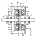
図1は本発明に係るマグネット式クラッチ装置の一実施例を示す縦断側面図、図2は同じく本発明に係るマグネット式ファンクラッチ装置の他の実施例を示す半截縦断側面図、図3は図2に示すマグネット式ファンクラッチ装置の永久磁石の配置構成を示す永久磁石回転体の一部正面図、図4は図2に示すマグネット式ファンクラッチ装置のマグネットカップリングと電磁クラッチの部分を拡大して示す部分斜視図、図5は本発明のマグネット式ファンクラッチ装置における電磁クラッチのON、OFF時の磁束の流れを示す概略説明図、図6は本発明のマグネット式ファンクラッチ装置のファン回転特性を従来と比較して示す図であり、1は入力軸、11は出力軸、2は固定軸、3、13は電磁クラッチ、4、14はマグネットカップリング、5、15a、15bはマグネティック・ループエレメント、6、16はアーマチャーである。 FIG. 1 is a longitudinal sectional side view showing an embodiment of a magnetic clutch device according to the present invention, FIG. 2 is a half sectional longitudinal view showing another embodiment of a magnetic fan clutch device according to the present invention, and FIG. FIG. 4 is a partial front view of a permanent magnet rotating body showing the arrangement of permanent magnets in the magnetic fan clutch device shown in FIG. 2, and FIG. FIG. 5 is a schematic explanatory view showing the flow of magnetic flux when the electromagnetic clutch is turned on and off in the magnetic fan clutch device of the present invention, and FIG. 6 is a fan rotation characteristic of the magnetic fan clutch device of the present invention. 1 is an input shaft, 11 is an output shaft, 2 is a fixed shaft, 3 and 13 are electromagnetic clutches, and 4 and 14 are magnetic couplings. , 5,15a, 15b is a magnetic loop element, is 6, 16 is an armature.
図1に示すマグネット式クラッチ装置は、入力軸1に電磁クラッチ3が、出力軸11にマグネットカップリング4がそれぞれ取付けられ、入力軸1および出力軸11に軸受装置7、17を介して回転可能に支承されたケース18にて電磁クラッチ3およびマグネットカップリング4が囲繞された構造となしたもので、前記電磁クラッチ3は入力軸1に固定されたクラッチロータ3−1および該ロータ内でケース18に固定された励磁コイル3−2とから構成されている。一方、マグネットカップリング4は出力軸11に軸受装置8を介して回転可能に支承された永久磁石回転体4−1、該回転体に装着された永久磁石4−2、該永久磁石の内周面側および外周面側に配設したマグネティック・ループエレメント5a、5b、前記回転体4−1に板ばね6−1にて前後動可能に保持されたアーマチャー6、前記出力軸11に固定されたフィン4−5付き円板4−3、前記永久磁石回転体4−1に装着された永久磁石4−2と僅かなギャップを隔てて対向するごとく前記円板4−3に取付けられた導体4−4(またはヒステリシス材)とで構成され、前記永久磁石4−2と導体4−4間に働く渦電流を伴なう吸引作用により当該永久磁石回転体4−1と前記導体4−4を有する円板4−3が相対回転する仕組みとなしている。
In the magnetic clutch device shown in FIG. 1, the
上記構成のマグネット式クラッチ装置において、入力軸1と一体にクラッチロータ3−1が回転している状態において電磁クラッチ3をONすると、クラッチロータ3−1内に装着された励磁コイル3−2によりアーマチャー6が吸引されてクラッチロータ3−1に吸着し、該クラッチロータ3−1と永久磁石回転体4−1が一体に回転する。この永久磁石回転体4−1が回転すると、該永久磁石回転体の永久磁石4−2と円板4−3に取着されている導体4−4間に働く渦電流による吸引作用により円板4−3が出力軸11と一体に回転する。
In the magnetic clutch device having the above configuration, when the
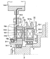
次に、図2〜図4に示すマグネット式ファンクラッチ装置は、非回転の固定軸2に電磁クラッチ13とマグネットカップリング14を設けた構成となしたもので、電磁クラッチ13は固定軸2に軸受装置9を介して回転自在に支承されたプーリ13−1a付きクラッチロータ13−1と、このクラッチロータ内に嵌合されかつステー13−3を介して固定軸2に固定された励磁コイル13−2とから構成されている。一方、マグネットカップリング14は同固定軸2に軸受装置10を介して回転自在に支承された永久磁石回転体14−1および該回転体に装着された永久磁石14−2、前記回転体14−1に板ばね16−1にて前後動可能に保持されたアーマチャー16、前記回転体14−1に軸受装置9−1を介して回転自在に支承されたファン14−4付き円板14−3、前記永久磁石回転体14−1に装着された永久磁石14−2と僅かなギャップを隔てて対向するごとく前記円板14−3に取付けられた導体14−5(またはヒステリシス材)とで構成され、前記永久磁石14−2と導体14−5間に働く渦電流による吸引作用により当該永久磁石回転体14−1と前記導体14−5を有する円板14−3が相対回転するごとく構成されている。
Next, the magnetic fan clutch device shown in FIGS. 2 to 4 has a configuration in which an
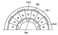
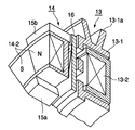
このマグネット式ファンクラッチ装置におけるマグネットカップリング14の永久磁石14−2は図3、図4に示すように多極構造となしている。すなわち、永久磁石回転体14−1の円周上に分割構造の永久磁石がN極、S極と交互に配置され、各磁石の内周面側と外周面側にマグネティック・ループエレメント15a、15bが交互に取付けられている。
The permanent magnet 14-2 of the
図2〜図4に示すマグネット式ファンクラッチ装置において、プーリ13−1aを介してクラッチロータ13−1が回転している状態において電磁クラッチ13をONすると、固定軸2に固定されている励磁コイル13−2により、永久磁石回転体14−1に前後動可能に保持されたアーマチャー16が吸引されてクラッチロータ13−1に吸着し、該クラッチロータ13−1と永久磁石回転体14−1が一体に回転する。この永久磁石回転体14−1が回転すると、該永久磁石回転体14−1の永久磁石14−2と円板14−3に取着されている導体14−5間に働く渦電流による吸引作用により円板14−3が回転しファン14−4が回転する。
In the magnet type fan clutch device shown in FIGS. 2 to 4, when the
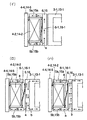
上記した図1、図2〜図4に示す各マグネット式(ファン)クラッチ装置において、電磁クラッチON、OFF時の作動を図5に基づいて説明すると、まず電磁クラッチがOFFの場合、アーマチャー6、16には永久磁石4−2、14−2の磁束は図5(イ)に矢印aで示すように流れているが、アーマチャー6、16は電磁クラッチ側へ移動しないため、クラッチロータ3−1、13−1のみ回転し、円板4−3、14−4は非回転状態にある。
次に、電磁クラッチがONの場合は、図5(ロ)に矢印bで示すようにクラッチロータ3−1、13−1に磁束が流れ、アーマチャー6、16がクラッチロータ側に吸着されてクラッチロータ3−1、13−1と永久磁石4−2、14−2が一体に回転する。この場合、永久磁石4−2、14−2から流れる磁束方向(矢印a)と、電磁クラッチ3、13の磁束方向(矢印b)を図示のように逆にした場合は、導体4−4、14−5側に流れる磁束は最小となり、ファン回転速度は最小となる。他方、図5(ハ)に示すように永久磁石4−2、14−2から流れる磁束方向(矢印a)と、電磁クラッチ3、13の磁束方向(矢印b)を図示のように同一にした場合は、導体4−4、14−5側に流れる磁束は最大となり、ファン回転速度は最大となる。
In each of the magnetic (fan) clutch devices shown in FIGS. 1 and 2 to 4 described above, the operation when the electromagnetic clutch is ON and OFF will be described with reference to FIG. 5. First, when the electromagnetic clutch is OFF, the
Next, when the electromagnetic clutch is ON, a magnetic flux flows through the clutch rotors 3-1 and 13-1, as indicated by an arrow b in FIG. The rotors 3-1 and 13-1 and the permanent magnets 4-2 and 14-2 rotate integrally. In this case, when the direction of the magnetic flux flowing from the permanent magnets 4-2 and 14-2 (arrow a) and the direction of the magnetic flux of the
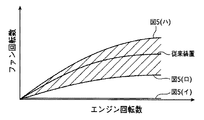
すなわち、本発明のマグネット式(ファン)クラッチ装置の場合は、ファン回転特性を図6に示すように電磁クラッチON時の永久磁石4−2、14−2から流れる磁束方向(矢印a)と、電磁クラッチ3、13の磁束方向(矢印b)を逆にした場合(図5ロ)のファン回転速度と、永久磁石4−2、14−2から流れる磁束方向(矢印a)と、電磁クラッチ3、13の磁束方向(矢印b)を同一にした場合(図5ハ)のファン回転速度との間のゾーン(斜線部)は、電磁クラッチの磁束方向の切替および電流値をコントロールすることにより自由にファンの回転速度を変化させることができる。
That is, in the case of the magnetic (fan) clutch device of the present invention, the fan rotation characteristics are determined by the magnetic flux direction (arrow a) flowing from the permanent magnets 4-2 and 14-2 when the electromagnetic clutch is ON, as shown in FIG. The fan rotation speed when the magnetic flux direction (arrow b) of the
本発明装置は、一般汎用機械の可変トルククラッチとしても応用できる。 The device of the present invention can also be applied as a variable torque clutch for general-purpose machines.
1 入力軸
2 固定軸
3、13 電磁クラッチ
4、14 マグネットカップリング
5a、5b、15a、15b マグネティック・ループエレメント
6、16 アーマチャー
11 出力軸
1
Claims (6)
6. The magnetic fan clutch device according to claim 4, wherein the clutch rotor and the permanent magnet rotating body are rotatably supported on the fixed shaft via a bearing device.
Priority Applications (5)
| Application Number | Priority Date | Filing Date | Title |
|---|---|---|---|
| JP2003367937A JP2004190853A (en) | 2002-11-28 | 2003-10-28 | Magnetic clutch system |
| US10/723,557 US6935477B2 (en) | 2002-11-28 | 2003-11-24 | Magnet type clutch device or magnet type fan clutch device |
| DE10355378A DE10355378A1 (en) | 2002-11-28 | 2003-11-25 | Coupling, combined of magnetic and electromagnetic coupling in order to change speed of rotating disk by changing direction of magnetic effect |
| KR10-2003-0084877A KR100518492B1 (en) | 2002-11-28 | 2003-11-27 | Magnet type clutch device or magnet type fan clutch device |
| CNB2003101186705A CN1309967C (en) | 2002-11-28 | 2003-11-28 | Magnetic iron type clutch device or magnetic iron type fan clutch device |
Applications Claiming Priority (2)
| Application Number | Priority Date | Filing Date | Title |
|---|---|---|---|
| JP2002345018 | 2002-11-28 | ||
| JP2003367937A JP2004190853A (en) | 2002-11-28 | 2003-10-28 | Magnetic clutch system |
Publications (1)
| Publication Number | Publication Date |
|---|---|
| JP2004190853A true JP2004190853A (en) | 2004-07-08 |
Family
ID=32396284
Family Applications (1)
| Application Number | Title | Priority Date | Filing Date |
|---|---|---|---|
| JP2003367937A Pending JP2004190853A (en) | 2002-11-28 | 2003-10-28 | Magnetic clutch system |
Country Status (5)
| Country | Link |
|---|---|
| US (1) | US6935477B2 (en) |
| JP (1) | JP2004190853A (en) |
| KR (1) | KR100518492B1 (en) |
| CN (1) | CN1309967C (en) |
| DE (1) | DE10355378A1 (en) |
Families Citing this family (14)
| Publication number | Priority date | Publication date | Assignee | Title |
|---|---|---|---|---|
| DE102004026796A1 (en) * | 2004-06-02 | 2005-12-29 | Daimlerchrysler Ag | Exhaust gas turbocharger for an internal combustion engine and method for operating an exhaust gas turbocharger |
| ITMI20040584U1 (en) * | 2004-10-26 | 2005-01-26 | Baruffaldi Spa | MOTION TRANSMISSION DEVICE FOR ROTATION TO A SHAFT DRIVEN SHAFT FOR FLUID RECIRCULATION PUMPS |
| US7184268B2 (en) * | 2005-01-10 | 2007-02-27 | Hewlett-Packard Development Company, L.P. | Dynamically adaptable electronics cooling fan |
| US7866959B2 (en) * | 2005-01-24 | 2011-01-11 | Hewlett-Packard Development Company, L.P. | Fan clutch for an electronics cooling fan |
| JP4625727B2 (en) * | 2005-06-30 | 2011-02-02 | 日立オートモティブシステムズ株式会社 | Electromagnetic actuator, clutch mechanism using the same, and power transmission mechanism of automobile |
| DE102008030165A1 (en) * | 2008-06-27 | 2009-12-31 | Linnig Trucktec Gmbh | Friction clutch for torque transmission |
| KR100975831B1 (en) * | 2010-02-22 | 2010-08-23 | 이미래테크 주식회사 | Double Clutch for Vehicle Compressors |
| US8732947B2 (en) | 2010-02-25 | 2014-05-27 | Kit Masters Inc. | Method for accessing components of a fan clutch system |
| CN101871495A (en) * | 2010-06-13 | 2010-10-27 | 龙口中宇机械有限公司 | Electromagnetic clutch magnet fixed disc with cyclone radiating fins |
| WO2011157207A1 (en) * | 2010-06-13 | 2011-12-22 | 龙口中宇机械有限公司 | Magnet fixing tray of electromagnetic clutch, manufacturing method and electromagnetic clutch thereof |
| US8464697B2 (en) * | 2010-08-13 | 2013-06-18 | Eaton Corporation | Integrated clutch supercharger |
| CN103343711B (en) * | 2013-07-12 | 2015-11-11 | 龙口中宇机械有限公司 | Arrangements for speed regulation |
| KR101804209B1 (en) * | 2015-11-09 | 2018-01-10 | 한승주 | Air Cooling Device |
| EP4063660A1 (en) * | 2021-03-26 | 2022-09-28 | Hilti Aktiengesellschaft | Machine tool with a motor shaft and a fan wheel, with a magnetic coupling between the motor shaft and the fan wheel |
Family Cites Families (8)
| Publication number | Priority date | Publication date | Assignee | Title |
|---|---|---|---|---|
| DE3739537A1 (en) * | 1987-11-21 | 1989-06-01 | Linnig Karl Heinz | ELECTROMAGNETICALLY OPERABLE DISC CLUTCH |
| JP3069044B2 (en) * | 1996-05-07 | 2000-07-24 | サンデン株式会社 | Electromagnetic coupling device |
| IT1292384B1 (en) * | 1997-06-19 | 1999-02-08 | Baruffaldi Spa | MOTORCYCLE TRANSMISSION DEVICE WITH ELECTROMAGNETIC CLUTCH AND EPICYCLOIDAL ROTISM FOR VEHICLE FANS |
| IT1303836B1 (en) * | 1998-11-19 | 2001-03-01 | Baruffaldi Spa | MOTORCYCLE TRANSMISSION DEVICE FOR FANS OF MOTOR VEHICLES ADDED TO INDUCTION WITH FRONT CHAIN |
| IT1316682B1 (en) * | 2000-02-29 | 2003-04-24 | Baruffaldi Spa | MOTORCYCLE TRANSMISSION DEVICE FOR MOTOR VEHICLES FANS COAXIAL GEAR |
| JP2002195303A (en) * | 2000-10-20 | 2002-07-10 | Usui Internatl Ind Co Ltd | Magnetic fan clutch device |
| US6634476B2 (en) * | 2000-10-20 | 2003-10-21 | Usui Kokusai Sangyo Kaisha, Limited | Magnet type fan clutch apparatus |
| DE10051985A1 (en) * | 2000-10-20 | 2002-05-02 | Ina Schaeffler Kg | fan clutch |
-
2003
- 2003-10-28 JP JP2003367937A patent/JP2004190853A/en active Pending
- 2003-11-24 US US10/723,557 patent/US6935477B2/en not_active Expired - Fee Related
- 2003-11-25 DE DE10355378A patent/DE10355378A1/en not_active Withdrawn
- 2003-11-27 KR KR10-2003-0084877A patent/KR100518492B1/en not_active Expired - Fee Related
- 2003-11-28 CN CNB2003101186705A patent/CN1309967C/en not_active Expired - Fee Related
Also Published As
| Publication number | Publication date |
|---|---|
| KR100518492B1 (en) | 2005-10-05 |
| CN1512086A (en) | 2004-07-14 |
| CN1309967C (en) | 2007-04-11 |
| KR20040047690A (en) | 2004-06-05 |
| DE10355378A1 (en) | 2004-06-24 |
| US6935477B2 (en) | 2005-08-30 |
| US20040118656A1 (en) | 2004-06-24 |
Similar Documents
| Publication | Publication Date | Title |
|---|---|---|
| EP1925070B1 (en) | Monopole field electric motor-generator with switchable coil configuration | |
| JP2004190853A (en) | Magnetic clutch system | |
| JP4623155B2 (en) | Power transmission device | |
| JP5527611B2 (en) | Electromagnetic clutch | |
| JP6327474B2 (en) | Outer rotor type variable field motor | |
| JP2010032035A (en) | Shifting electromagnetic clutch | |
| WO2012147510A1 (en) | Electromagnetic clutch | |
| KR101628595B1 (en) | Electromagnetic clutch | |
| JP2006238623A (en) | Dc motor | |
| JP2014101902A (en) | Clutch mechanism | |
| JP4504853B2 (en) | Motor structure | |
| JPH07293594A (en) | Clutch device | |
| JP2008544168A (en) | Rotary electromagnetic coupling device | |
| JP5983385B2 (en) | clutch | |
| JP4293418B2 (en) | Magnet type fan clutch device | |
| JPH0851745A (en) | Miniature synchronous motor | |
| JP3716227B2 (en) | Geared motor | |
| JP2011085180A (en) | Variable speed electromagnetic clutch | |
| JPS6329909Y2 (en) | ||
| JP2002262512A (en) | Geared motor | |
| CN112421871B (en) | Motor assembly, food processor and air supply device | |
| JP2005048793A (en) | Magnet type fan clutch device | |
| JP5257716B2 (en) | Electromagnetic clutch | |
| JP2522125Y2 (en) | Electromagnetic coupling device | |
| JP2002340036A (en) | Electromagnetic clutch |
Legal Events
| Date | Code | Title | Description |
|---|---|---|---|
| A621 | Written request for application examination |
Free format text: JAPANESE INTERMEDIATE CODE: A621 Effective date: 20061027 |
|
| RD03 | Notification of appointment of power of attorney |
Free format text: JAPANESE INTERMEDIATE CODE: A7423 Effective date: 20080527 |
|
| A521 | Written amendment |
Free format text: JAPANESE INTERMEDIATE CODE: A523 Effective date: 20080530 |
|
| A131 | Notification of reasons for refusal |
Free format text: JAPANESE INTERMEDIATE CODE: A131 Effective date: 20090917 |
|
| A977 | Report on retrieval |
Free format text: JAPANESE INTERMEDIATE CODE: A971007 Effective date: 20090917 |
|
| A02 | Decision of refusal |
Free format text: JAPANESE INTERMEDIATE CODE: A02 Effective date: 20100205 |