JP2004190734A - Rolling bearing - Google Patents
Rolling bearing Download PDFInfo
- Publication number
- JP2004190734A JP2004190734A JP2002357237A JP2002357237A JP2004190734A JP 2004190734 A JP2004190734 A JP 2004190734A JP 2002357237 A JP2002357237 A JP 2002357237A JP 2002357237 A JP2002357237 A JP 2002357237A JP 2004190734 A JP2004190734 A JP 2004190734A
- Authority
- JP
- Japan
- Prior art keywords
- rolling
- raceway
- bearing
- rolling element
- retainer
- Prior art date
- Legal status (The legal status is an assumption and is not a legal conclusion. Google has not performed a legal analysis and makes no representation as to the accuracy of the status listed.)
- Pending
Links
Images


Classifications
-
- Y—GENERAL TAGGING OF NEW TECHNOLOGICAL DEVELOPMENTS; GENERAL TAGGING OF CROSS-SECTIONAL TECHNOLOGIES SPANNING OVER SEVERAL SECTIONS OF THE IPC; TECHNICAL SUBJECTS COVERED BY FORMER USPC CROSS-REFERENCE ART COLLECTIONS [XRACs] AND DIGESTS
- Y02—TECHNOLOGIES OR APPLICATIONS FOR MITIGATION OR ADAPTATION AGAINST CLIMATE CHANGE
- Y02T—CLIMATE CHANGE MITIGATION TECHNOLOGIES RELATED TO TRANSPORTATION
- Y02T10/00—Road transport of goods or passengers
- Y02T10/80—Technologies aiming to reduce greenhouse gasses emissions common to all road transportation technologies
- Y02T10/86—Optimisation of rolling resistance, e.g. weight reduction
Abstract
Description
【0001】
【発明の属する技術分野】
本発明は、ラジアル荷重と両方向のアキシアル荷重、モーメント荷重を受けられる軸受に関するものであり、産業機械,ロボット,医療機器,食品機械,半導体/液晶製造装置,ダイレクトドライブモータ,光学及びオプトエレクトロニクス装置などに使われる。
【0002】
【従来の技術】
一つの軸受でラジアル荷重と両方向のアキシアル荷重,モーメント荷重を受けられるものとしては、従来、クロスローラ軸受、4点接触玉軸受及び3点接触玉軸受が知られている。
クロスローラ軸受では、転動体がころであり、転動体と軌道輪が2箇所で線接触するので、モーメント剛性大の長所を持つ。
4点接触玉軸受又は3点接触玉軸受では、転動体が玉であり、転動体と軌道輪が4箇所又は3箇所で点接触するので、低トルク、作動円滑の長所を持つ。
【0003】
【発明が解決しようとする課題】
しかしながら、クロスローラ軸受では、モーメント剛性大という長所を持つ一方、転動体と軌道輪の間に相対速度が生じるため、ころがスキューし易く、その結果、トルク変動が生じ易い短所もある。
4点接触玉軸受又は3点接触玉軸受は、転動体が玉なので、同寸法のクロスローラよりトルクが小さい長所を持つ一方、モーメント剛性小という短所もある。また、アキシアル荷重に対してラジアル荷重が優勢な場合又は純ラジアル荷重を受ける場合、各玉は、軌道輪と4点又は3点で接触するため、玉のスピンが大きく、小さなスピン摩耗性能は得られない。
さらに、通常、スピン摩耗性能を少しでも改善するためには、軸受の隙間が正に設定されるので、結果として軸受のモーメント剛性が小さくなってしまう。
【0004】
そこで、このような問題点を解決する新規有用な転がり軸受として特開2001−50264が提供されている。
すなわち、図8に示すように、一対の軌道輪たる外輪100と内輪200の間に複数の転動体400が組み込まれ、上記各軌道輪100,200は転動体400の半径より大径状の軌道面101,201からなる軌道溝300を夫々有し、その中に少なくとも一つの軌道輪100(200)は二つの軌道面からなり、上記各転動体400は転がり接触面となる外径401が軸方向にも曲率を持ち、円周上に夫々交互に交差状に配されると共に、各転動体400の外径401が常に相対する一方の軌道輪100(200)の軌道面101(201)と他方の軌道輪200の軌道面201(101)にて夫々一点ずつ合計二点で接触している構成の転がり軸受である。そして上記転動体400の具体的な形態は、図8,9に示す通り、一組の平面部(相対面)402,402を有する上下切断状玉(玉の上下部分を切断して相対面を形成した構造のものをいう。以下本明細書において同じ。)で、外径401を転がり接触面としている。
特開2001−50264では、上記形態の転動体400の姿勢を安定させるため、少なくともポケット600の軸方向の相対する二面(軸方向案内面)601,601で拘束して案内する保持器500を用いていた(図8・9)。しかし、この保持器500のポケット600に転動体400を収めるには、事実上軸受を組み立てるときに、少なくとも外輪100と内輪200のいずれかを分割しなければならない。このため、組み立て時に、分割された外輪100,100の半径方向ずれ等を管理する必要があった。図中、700は締結ボルトである。また、軌道輪分割構成による軸受の低コスト化が達成し難い大きな課題となっている。
また、上述のような転動体400を用いた転がり軸受としてDE4334195がある。しかし、DE4334195では、内外輪は共に一体型で構成されているが、内輪及び外輪の軌道溝には、何等この外輪と内輪で形成される溝空間内にて転動体を回転させるための特別の構成を有していない。このため、特に予圧が掛かる場合、この溝空間内で転動体を回転させることは困難で、組み立ても事実上困難と思われる。
本発明は、上述した従来技術の有するこのような問題点に鑑みなされたものであり、その目的とするところは、転動体と軌道溝とのスピン滑りの抑制と共に、転がり抵抗を低くして低トルク化を実現した転がり軸受において、軌道輪一体型であっても転動体の組み込みが容易になし得るものとすることである。
また、この種の軸受で一体型の軌道輪と保持器を組み立てた状態でも転動体の組み込みが容易になし得るものとすることである。
【0005】
【課題を解決するための手段】
上記課題を達成するために本発明がなした技術的手段は、一対の軌道輪間に保持器を介して複数の転動体が組み込まれ、上記各軌道輪は転動体の半径より大径状の軌道面からなる軌道溝を夫々有し、その中に少なくとも一つの軌道輪は二つの軌道面からなり、上記各転動体は転がり接触面となる外径が軸方向にも曲率を持ち、円周上に夫々交互に交差状に配されると共に、各転動体の外径が常に相対する一方の軌道輪の軌道面と他方の軌道輪の軌道面にて夫々一点ずつ合計二点で接触しているものであって、一対の軌道輪は夫々一体型で形成され、該軌道輪のいずれか一方若しくは双方の軌道溝の一部には、所望深さの溝を設けたことである。
また、上記保持器は、転動体を保持する夫々のポケットが、周方向に相対する二面のポケット面を有すると共に、軸方向は一面のポケット面のみ有し、相対する面側は開放されており、該軸方向のポケット面は、互いに交差状に組み込まれる転動体の傾斜の向きに対応して、互いに軸方向の反対側に傾斜状に配列されている。転動体は、少なくとも一平面を有し、該平面が保持器の軸方向ポケット面と接する。
このような技術的手段により、転動体は、内外輪保持器を組み立てた状態でも挿入可能である。そして、挿入された転動体は、軌道溝に小さな溝を設けたことにより、軌道輪が一体型であっても、その軌道輪間で形成される溝空間内で転動体が回転可能となる。また、保持器ポケットの軸方向の片側が開放しているので、内外輪、保持器を組み込んだ状態で、片側ずつ組み込むことが可能となる。また、このような保持器構成を採用することにより、転動体の軸方向案内面が、従来の二面から一面に減少しているため、転動体を拘束する力が減少する。その結果、保持器と転動体の間に生じる端面摩擦が大幅(約半分)に小さくなるためトルクも減少する。
【0006】
【発明の実施の形態】
以下、本発明の一実施形態を図に基いて説明する。なお、本実施形態は本発明の一実施形態にすぎず、これに限定して解釈されるものではなく本発明の範囲内で設計変更可能である。
転がり軸受Aは、図1に開示しているように、一体型で成形された軸受軌道輪(軸受外輪)1の内径と、同じく一体型に成形された軸受軌道輪(軸受内輪)2の外径に形成される軌道溝3に、保持器6を介して複数の転動体5,5…が組み込まれて構成されている。なお、図中、8はシール溝で、本実施形態では密封板(シール・シールド)を図示省略しているが、密封板は必要に応じて適宜設けることが出来る。なお、軸受寸法・接触角・転動体径あるいは材質などの諸構成は限定されない。
本実施形態によれば、軌道輪としての外輪1と内輪2のいずれも一体型で成形されているため、締結ボルトなどの関連部品を含めた軌道輪の製作コスト・組み立て管理および組み立て費が大幅に削減できた。
軌道溝3は、転動体5の半径よりも大きな半径の軌道面1a・1b,2a・2bにより形成されている。
また、少なくともいずれか一方の軌道輪の軌道溝が、二つの軌道面から構成されているものであればよく本発明の範囲内で適宜選択される。
各軌道面1a・1b,2a・2bの形状は、転動体5の転がりに適切な形状を有しているものであれば、断面アーチ状あるいはV字状等任意で、また曲線状あるいは直線状等のいずれであってもよく特に限定されるものではないが、例えば本実施形態では、円心をクロスに配置した両円弧で形成されている、いわゆるゴシックアーチが適用される。
【0007】
そして、内輪2の軌道溝3の一部に、この軌道溝3よりも小さな溝4を凹設している。
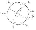
本実施形態では、内輪軌道面2a,2bからなる軌道溝3の中心に、周方向に連続する所望深さの断面半円状の小径(例えば溝半径は約0.8mm)な溝とする。この溝4は、転動体5の組み込み時における回転用溝として主に使用される。すなわち、後述する転動体5の転がり接触面5aと平面部5bとの繋ぎ部(交点)5fを、組み込み時に溝4内に挿入させることによって、転動体5を軌道溝3空間内で回転可能とする。なお、溝4は、その溝4内に潤滑剤を保有させておくことも可能で、軌道面内に備えられる潤滑剤(油、グリースなど)保有機能としての作用もあり、安定した軸受寿命が期待できる。
溝4の形状・径方向深さ・軸方向幅は、軌道面を可能な限り大きく取れるように最小限の大きさにするのが好ましいが、転動体5の転がり接触面5aと平面部5bとの繋ぎ部5fが溝4内に一部挿入可能であれば全て本発明の範囲内であり、特に図示形態に限定されず本発明の範囲内で適宜設計変更可能である。例えば45度程度の面取り程度でもよい。
また、転動体5の周方向配設間隔を考慮すれば、溝4は所望長さをもって周方向に断続して設けてもよく本発明の範囲内である。
なお、軌道面2a,2bとの繋ぎ部2cのエッジを無くしR状に形成してもよい。
この溝4は、本実施形態では上述の通り内輪2の軌道溝3にのみ設けているが、外輪1の軌道溝3に設けてもよく、また外輪1と内輪2の双方に設けてもよい。
【0008】
転動体5は、転がり接触面となる外径5aが軸方向に曲率を持ち、かつ軌道面1a・1b,2a・2bの夫々の半径よりも小径の半径を有する任意形状で、該転動体5は、隣接する転動体5が夫々交互に交差状に配されると共に、各転動体5の外径5aが、常に一方の軌道輪1の軌道面1a・1bと他方の軌道輪2の軌道面2b,2aにて二点接触している。
転動体5は、例えば本実施形態では図3に拡大して開示しているように、一組の平面部(本実施形態では相対面)5b,5bを有する上下切断状玉(玉の上下部分を切断して平面部5b,5bを形成した構造のものをいう。以下同じ。)で、該平面部5b,5bに垂直する自転中心軸5cが夫々交差状となるように夫々の転動体5,5…が組込まれると共に、各転動体5の外径5aが、常に一方の軌道輪1の軌道面1a,1bと他方の軌道輪2の軌道面2b,2aにて二点接触している。図中5fは、転動体5の転がり接触面5aと平面部5bとの繋ぎ部(交点)である。
転動体5は、その上下の切断幅は特に限定されず、また上下の切断割合は、均等あるいは均等でないものであってもよく、本発明の範囲内で任意に選択可能である。すなわち、本実施形態では、平面部5b,5bを対称としたが、転動体5の平面部5b,5bは、対称であっても非対称であってもよくいずれも本発明の範囲内である。
また、図4に示す非対称の平面部5b,5dを有する転動体(上下切断状玉)5の場合、大端側の平面部5dが軸受の内輪2に向くように配することで、転動体5の回転がより安定になり、より低トルクを実現することができる。
転動体5の全体形状、相対面5b,5bの有無や、外径5aにおける軸方向の曲率の大小等は、上記具体的形状に何等限定されるものではなく、本発明の範囲内において任意に変更可能である。すなわち、例えば、平面部5b,5bに代えて、非平行状の両面(平面部)を備え、該両面に垂直する自転中心軸を有するものとしてもよい(図示省略)。
また、図5に示す玉の片側をカット(切断)して一つの平面部(カット面)5eを設けた片側カット状玉としたものであってもよい。
また、平面部5b(5d,5e)は、任意形状であって、適宜最適な形状・大きさに変更・選択できる。
【0009】
転動体5,5…の組込みは、隣り合う転動体5,5における各平面部5b・5b,5b・5bに垂直する自転中心軸5c,5cが交互に交差状となるようにする。なお、その交差状態は直交状・非直交状のいずれでも構わない。
また、転動体5の交差状に配される方式は、両方のなりで数が同じなら、周方向に交互に配されるものでなくともよく特に限定されない。すなわち、転動体5が1ヶ毎に交差してもよく、1ヶ毎に交差しなくとも両方のなりで数が同じなら、2ヶずつ交差あるいは2ヶ1ヶ1ヶ2ヶ等のように交差していてもよくいずれも本発明の範囲内である。
【0010】
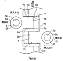
各転動体5,5の運動は、保持器6で案内される(図2参照)。
保持器6は、転動体5を保持案内するポケット(保持部)7…が、周方向に複数個備えられた円環状に形成され、夫々のポケット7が、周方向に相対する二面のポケット面(周方向案内面)7a,7aを有すると共に、軸方向は一面のポケット面(軸方向に転動体姿勢を安定させる軸方向案内面)7bのみ有し、相対する面側は開放(開放面)されており、該軸方向のポケット面7bは、互いに交差状に組み込まれる転動体5の傾斜の向きに対応して、互いに軸方向の反対側に傾斜状に配列されている。なお周方向のポケット面7aの形状は特に限定されず任意である。
軸方向のポケット面7bは、転動体5の外輪対向側の平面部5b(図1で左上方に向いている面)を案内するよう外径6aから内径6bにわたり傾斜状に形成されている。よって、ポケット7の外径側開口7cより内径側開口7dが広く形成されることとなる。
このポケット面7bの傾斜角度は任意で、軌道溝3空間内で配される転動体5の角度を考慮して決定される。
本実施形態では、円周上で転動体5…数量と同一数量をもって等間隔で設けられると共に、周方向で隣り合うポケット7の軸方向ポケット面7bは、周方向に交互に交差状に配されており、隣り合う各転動体5,5を上述の通り平面部5b・5b,5b・5bに垂直する自転中心軸5c,5cが夫々交差状になるように交互に組み込み可能とする。
なお、本実施形態では、円周上で転動体5…数量と同一数量のポケット7…が等間隔で、かつ交互に交差状に配されているが、特に限定されず、両方のなりで数が同じなら、2ヶずつ交差あるいは2ヶ1ヶ1ヶ2ヶ等のように交差していても良く本発明の範囲内である。よって、上述した転動体5の配される方式に応じたポケット構成を周方向に設けた保持器とする。
保持器6の案内方式は特に限定されるものではなく、内輪案内でも、外輪案内でも、転動体案内でもよい。また、本実施形態では保持器6を一体型の構成としているが、特に限定されるものではなく、幾つかの部分から形成したものでも良い。
本実施形態の保持器6によれば、外輪1、内輪2と共に組み立てた後、転動体5を保持器6の開放側より軸受軌道溝3空間内へ順次挿入できる。
【0011】
本実施形態は予圧品であるが、すきま品でもよいことは言うまでもない。
転動体と軌道面との間における予圧の付与される状態は特に限定されず、すなわち、製造段階で予圧が付与されても付与されなくてもよくいずれも本発明の範囲内である。
【0012】
これら軸受の軌動輪1,2と転動体5の材質としては、通常軸受鋼が用いられるが、使用環境に応じて耐食性や、耐熱性を向上させる場合にはステンレス鋼やセラミック等が適宜選択される。
また保持器6の材料としては、もみ抜き保持器、プレス保持器、樹脂保持器等が適宜選択されるので、例えば黄銅や鉄等の金属や、例えばポリアミド66(ナイロン66)・ポリフェニレンサルファイド(PPS)等の合成樹脂が本発明の範囲内で選ばれる。
【0013】
この実施形態によれば、転動体5の外径5aが相対する外輪1の軌道面1bと内輪2の軌道面2aに夫々点接触(接触点を11,11で示す)し、隣接する転動体5が外輪1の軌道面1aと内輪2の軌道面2bに夫々点接触(接触点を12,12で示す)する。転動体5,5の接触角交互に交差するので、一つの軸受でラジアル荷重と両方向のアキシアル荷重、モーメント荷重を受けることができる。
【0014】
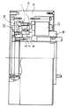
さらに、本実施形態の転がり軸受Aは、図6に開示しているようにダイレクトドライブモータに組み込むことにより従来品に比して優れたこの種のモータが提供できる。
図6はダイレクトドライブモータの一実施形態を示す概略図で、図中17は回転子(ロータ)、18は固定子(ステータ)、21はコイルを示し、回転子17と固定子18との間に転がり軸受Aが組み込まれ、コイル21に通電することにより、ロータ17およびパルサーリング19が回転し、パルサーリング19の凹凸を位置検出器20により検出し、制御器(図示しない)によって回転速度や位置決めの制御を行う構造となっている。本実施形態では、モータの外側が回転するアウターロータ型にて説明しているが、モータの内側が回転するインナーロータ型に採用しても何等問題はない。
軸受外輪1はロータ17に嵌合され、パルサーリング19とともに固定される。一方、軸受内輪2はコイル21の巻かれたステータ18側に嵌合され、位置検出器20と共に固定されている。
本実施形態のダイレクトドライブモータは、転がり軸受A構成部分を除いて従来のダイレクトドライブモータと同一の周知構成であるため、特に図示例に限定されるものではなく、他の周知構成が本発明の範囲内で適宜設計変更可能である。このように、ダイレクトドライブモータに内蔵される軸受Aの構成を、上述の実施形態にて説明した本発明の転がり軸受とすることにより、軸受のトルクを従来のクロスローラ軸受よりも小さく出来、発熱が抑えられる。また、前記軸受に予圧を付与することにより剛性が得られる。従って、従来のダイレクトドライブモータの機能を損うこと無く、高速化が可能となる。
【0015】
ここで、本実施形態の転がり軸受(図1実施形態品)Aと、従来の転がり軸受(図8従来品)の軸受トルクとその変動について比較した実験結果を図7に示す。

なお、外輪を加熱することなく転動体を内、外輪の相対変位を利用し、直接溝に押し込んでも可能であることを確認した。但し、挿入時に転動体の転がり接触面に傷がつかないように注意が必要である。
【0016】
【発明の効果】
本発明は、上述の通りの構成としたため次の作用効果を奏する。
▲1▼従来のように、一対の軌道輪のうちいずれか一方を少なくとも分割する構成としなくとも、転動体の組み込みがなし得るため、軌道輪の製作コスト・組み立て管理および組み立て費が大幅に削減できた。
▲2▼軌道輪のいずれもが分割構成としないため、分割構成とするときに要する締結用のボルト・リベットなどの関連部品が不要となり、部品削減が図れた。その結果、これらに要していた製作コスト・製作手間、および管理などが削減できた。
▲3▼一体型で加工された軌道輪の加工精度を損なうことなく軸受とすることができるため、軸受精度を高く維持できる。
▲4▼本発明を構成する保持器によれば、一対の軌道輪・保持器を組み立てた後に、各ポケットにおける開放側を介して軸方向から転動体を容易に組み込むことができる。
▲5▼軌道溝に設けた溝は、転動体組み込み時の転動体回転用としての機能を有すると共に、軌道面内に、油・グリースなどの潤滑剤の保有機能も有するため、安定した軸受寿命が期待できる。
【図面の簡単な説明】
【図1】本発明転がり軸受の一実施形態を一部省略して示す概略断面図。
【図2】本発明転がり軸受における保持器への転動体組み込み方向を一部省略して示す概略平面図。
【図3】本発明転がり軸受に組み込まれる転動体の一実施形態を示す斜視図。
【図4】本発明転がり軸受に組み込まれる転動体の他の実施形態を示す斜視図。
【図5】本発明転がり軸受に組み込まれる転動体の他の実施形態を示す斜視図。
【図6】ダイレクトドライブモーターに本発明転がり軸受を組み込んだ実施の一形態を一部切欠いて示す概略断面図。
【図7】本実施形態軸受と従来の軸受の軸受トルクとその変動を示す実験結果の図。
【図8】従来の転がり軸受を一部省略して示す概略断面図。
【図9】従来の転がり軸受における保持器への転動体組み込み方向を一部省略して示す概略平面図。
【符号の説明】
A:転がり軸受
1:外輪
2:内輪
3:軌道溝
4:溝(回転用)
5:転動体
5a:外径
5b:平面部
5f:繋ぎ部
6:保持器
7:ポケット
7b:軸方向ポケット面[0001]
TECHNICAL FIELD OF THE INVENTION
The present invention relates to a bearing capable of receiving a radial load, an axial load in both directions, and a moment load, and includes an industrial machine, a robot, a medical device, a food machine, a semiconductor / liquid crystal manufacturing device, a direct drive motor, an optical and optoelectronic device, and the like. Used for
[0002]
[Prior art]
Conventionally, as a bearing capable of receiving a radial load, an axial load and a moment load in both directions, a cross roller bearing, a four-point contact ball bearing and a three-point contact ball bearing are known.
In the cross roller bearing, the rolling element is a roller, and the rolling element and the race ring are in line contact with each other at two places, so that the advantage of large moment rigidity is obtained.
In a four-point contact ball bearing or a three-point contact ball bearing, the rolling element is a ball, and the rolling element and the bearing ring make point contact at four or three points, so that they have advantages of low torque and smooth operation.
[0003]
[Problems to be solved by the invention]
However, the cross roller bearing has an advantage of high moment rigidity, but has a disadvantage that the relative speed is generated between the rolling element and the bearing ring, so that the rollers are easily skewed, and as a result, torque fluctuation is apt to occur.
The four-point contact ball bearing or the three-point contact ball bearing has the advantage that the torque is smaller than the cross roller of the same size because the rolling element is a ball, but also has the disadvantage that the moment rigidity is small. Also, when the radial load is dominant over the axial load or when a pure radial load is received, each ball contacts the raceway at four or three points, so that the ball has large spin and small spin wear performance is obtained. I can't.
Further, usually, in order to improve the spin wear performance even a little, the gap of the bearing is set to be positive, and as a result, the moment rigidity of the bearing is reduced.
[0004]
Therefore, Japanese Patent Application Laid-Open No. 2001-50264 is provided as a new and useful rolling bearing that solves such a problem.
That is, as shown in FIG. 8, a plurality of
In Japanese Patent Application Laid-Open No. 2001-50264, in order to stabilize the posture of the
Further, as a rolling bearing using the
SUMMARY OF THE INVENTION The present invention has been made in view of the above-mentioned problems of the related art, and has as its object to suppress the spin sliding between a rolling element and a raceway groove and to reduce the rolling resistance to reduce the rolling resistance. It is an object of the present invention to make it possible to easily incorporate a rolling element in a rolling bearing that realizes torque, even if the rolling bearing is of an integral type.
Another object of the present invention is to make it possible to easily incorporate a rolling element even in a state where an integrated race and a retainer are assembled with this type of bearing.
[0005]
[Means for Solving the Problems]
Technical means achieved by the present invention to achieve the above object is that a plurality of rolling elements are incorporated via a retainer between a pair of races, and each of the races has a larger diameter than the radius of the rolling bodies. Each has a raceway groove formed of a raceway surface, and at least one raceway ring has two raceway surfaces therein, and each of the rolling elements has an outer diameter serving as a rolling contact surface also having a curvature in the axial direction, and a circumferential surface. The rolling elements are arranged alternately in an intersecting manner, and the outer diameters of the rolling elements are always in contact with each other at one point on the raceway surface of one raceway and the raceway surface of the other raceway at a total of two points. That is, the pair of races are formed integrally, and a groove of a desired depth is provided in one or both raceways of the race.
Further, in the retainer, each pocket holding the rolling element has two pocket surfaces facing each other in the circumferential direction, has only one pocket surface in the axial direction, and the facing surface side is open. The pocket surfaces in the axial direction are arranged obliquely on opposite sides in the axial direction so as to correspond to the inclination directions of the rolling elements incorporated into each other in an intersecting manner. The rolling element has at least one plane, which is in contact with the axial pocket surface of the cage.
By such technical means, the rolling elements can be inserted even when the inner and outer race retainers are assembled. Since the inserted rolling element has a small groove in the raceway groove, the rolling element can rotate in the groove space formed between the raceways even if the raceway is integral. Also, since one side in the axial direction of the retainer pocket is open, it is possible to incorporate the inner and outer rings and the retainer one by one in a state of being incorporated. Further, by adopting such a retainer configuration, the axial guide surface of the rolling element is reduced from the conventional two surfaces to one surface, so that the force for restraining the rolling element is reduced. As a result, the end face friction generated between the retainer and the rolling element is significantly (about half) reduced, so that the torque is also reduced.
[0006]
BEST MODE FOR CARRYING OUT THE INVENTION
Hereinafter, an embodiment of the present invention will be described with reference to the drawings. Note that this embodiment is merely an embodiment of the present invention, and is not to be construed as being limited to the embodiment, and the design can be changed within the scope of the present invention.
As disclosed in FIG. 1, the rolling bearing A has an inner diameter of an integrally formed bearing race ring (bearing outer ring) 1 and an outer periphery of a similarly integrally formed bearing race ring (bearing inner ring) 2. A plurality of
According to the present embodiment, since both the
The
In addition, it is sufficient that at least one of the raceways has a raceway groove composed of two raceway surfaces, and is appropriately selected within the scope of the present invention.
The shape of each
[0007]
A
In the present embodiment, a groove having a semicircular cross-section (for example, a groove radius of about 0.8 mm) having a desired depth in a circumferential direction and having a desired depth is formed at the center of the
The shape, radial depth and axial width of the
Further, in consideration of the interval between the
The edge of the connecting
In this embodiment, the
[0008]
The rolling
The rolling
The upper and lower cutting widths of the rolling
In the case of a rolling element (vertical cut ball) 5 having asymmetrical
The overall shape of the rolling
Alternatively, one side of the ball shown in FIG. 5 may be cut (cut) to form a one-side cut ball provided with one flat portion (cut surface) 5e.
The
[0009]
The rolling
In addition, the method of arranging the rolling
[0010]
The movement of each rolling
The
The
The inclination angle of the
In this embodiment, the same number of
In the present embodiment, the same number of the rolling
The guide system of the
According to the
[0011]
Although the present embodiment is a preload product, it goes without saying that a clearance product may be used.
The state in which the preload is applied between the rolling element and the raceway surface is not particularly limited, that is, the preload may or may not be applied in the manufacturing stage, and both are within the scope of the present invention.
[0012]
Usually, bearing steel is used as a material for the
As the material of the
[0013]
According to this embodiment, the
[0014]
Further, by incorporating the rolling bearing A of the present embodiment into a direct drive motor as disclosed in FIG. 6, a motor of this type which is superior to a conventional product can be provided.
FIG. 6 is a schematic view showing an embodiment of a direct drive motor, in which 17 is a rotor (rotor), 18 is a stator (stator), 21 is a coil, and a portion between the
The bearing
The direct drive motor of the present embodiment has the same well-known configuration as the conventional direct drive motor except for the rolling bearing A component, and is not particularly limited to the illustrated example. The design can be appropriately changed within the range. As described above, the configuration of the bearing A incorporated in the direct drive motor is the rolling bearing of the present invention described in the above-described embodiment, so that the torque of the bearing can be made smaller than that of the conventional cross roller bearing, and heat generation can be achieved. Is suppressed. Further, rigidity can be obtained by applying a preload to the bearing. Therefore, the speed can be increased without impairing the function of the conventional direct drive motor.
[0015]
Here, FIG. 7 shows an experimental result comparing the bearing torque of the rolling bearing A of the present embodiment (the product of the embodiment of FIG. 1) A with the conventional rolling bearing (the conventional product of FIG. 8) and its fluctuation.
In addition, it was confirmed that the rolling element can be directly pushed into the groove using the relative displacement of the inner and outer rings without heating the outer ring. However, care must be taken so that the rolling contact surface of the rolling element is not damaged during insertion.
[0016]
【The invention's effect】
The present invention has the following functions and effects due to the configuration described above.
(1) Unlike the conventional case, the rolling element can be incorporated without having to split at least one of the pair of races, so that the production cost, the assembly management and the assembly cost of the race are greatly reduced. did it.
{Circle around (2)} Since none of the races has a split configuration, related parts such as fastening bolts and rivets required for the split configuration are not required, and the number of components can be reduced. As a result, the production cost, production labor, management, and the like required for these were reduced.
{Circle over (3)} Since the bearing can be formed without impairing the processing accuracy of the raceway formed integrally, the bearing accuracy can be maintained high.
(4) According to the retainer constituting the present invention, after assembling the pair of races / retainers, the rolling elements can be easily incorporated from the axial direction through the open side of each pocket.
(5) The groove provided in the raceway groove has the function of rotating the rolling element when the rolling element is incorporated, and also has the function of retaining lubricant such as oil and grease in the raceway surface, so that the stable bearing life Can be expected.
[Brief description of the drawings]
FIG. 1 is a schematic sectional view showing a rolling bearing according to an embodiment of the present invention with a part thereof omitted;
FIG. 2 is a schematic plan view showing the rolling bearing of the present invention with a partly omitted illustration of a direction in which rolling elements are incorporated into a cage.
FIG. 3 is a perspective view showing one embodiment of a rolling element incorporated in the rolling bearing of the present invention.
FIG. 4 is a perspective view showing another embodiment of the rolling element incorporated in the rolling bearing of the present invention.
FIG. 5 is a perspective view showing another embodiment of the rolling element incorporated in the rolling bearing of the present invention.
FIG. 6 is a schematic sectional view showing an embodiment in which the rolling bearing of the present invention is incorporated in a direct drive motor, with a part cut away.
FIG. 7 is a graph of experimental results showing bearing torques of the bearing of the present embodiment and a conventional bearing and their fluctuations.
FIG. 8 is a schematic cross-sectional view partially showing a conventional rolling bearing.
FIG. 9 is a schematic plan view partially showing a direction in which rolling elements are incorporated into a cage in a conventional rolling bearing.
[Explanation of symbols]
A: Rolling bearing 1: Outer ring 2: Inner ring 3: Track groove 4: Groove (for rotation)
5: rolling
Claims (3)
上記各軌道輪は転動体の半径より大径状の軌道面からなる軌道溝を夫々有し、
その中に少なくとも一つの軌道輪は二つの軌道面からなり、
上記各転動体は転がり接触面となる外径が軸方向にも曲率を持ち、円周上に夫々交互に交差状に配されると共に、
各転動体の外径が常に相対する一方の軌道輪の軌道面と他方の軌道輪の軌道面にて夫々一点ずつ合計二点で接触しているものであって、
一対の軌道輪は夫々一体型で形成され、
該軌道輪のいずれか一方若しくは双方の軌道溝の一部には、所望深さの溝を設けたことを特徴とする転がり軸受。A plurality of rolling elements are incorporated via a retainer between a pair of races,
Each of the races has a raceway groove having a raceway surface having a diameter larger than the radius of the rolling element,
In which at least one orbit consists of two raceways,
Each of the rolling elements has an outer diameter serving as a rolling contact surface also has a curvature in the axial direction, and is alternately arranged on the circumference in an alternating manner.
The outer diameter of each rolling element is always in contact with the raceway surface of one raceway and the raceway surface of the other raceway, each of which is in contact with the raceway surface at a total of two points.
Each of the pair of bearing rings is integrally formed,
A rolling bearing characterized in that a groove of a desired depth is provided in a part of one or both raceways of the race.
Priority Applications (5)
| Application Number | Priority Date | Filing Date | Title |
|---|---|---|---|
| JP2002357237A JP2004190734A (en) | 2002-12-09 | 2002-12-09 | Rolling bearing |
| US10/501,213 US20050117827A1 (en) | 2002-01-11 | 2003-01-09 | Rolling bearing |
| PCT/JP2003/000131 WO2003060340A1 (en) | 2002-01-11 | 2003-01-09 | Rolling bearing |
| DE10392207T DE10392207T5 (en) | 2002-01-11 | 2003-01-09 | roller bearing |
| CNB038045028A CN100340782C (en) | 2002-01-11 | 2003-01-09 | Rolling bearing |
Applications Claiming Priority (1)
| Application Number | Priority Date | Filing Date | Title |
|---|---|---|---|
| JP2002357237A JP2004190734A (en) | 2002-12-09 | 2002-12-09 | Rolling bearing |
Publications (1)
| Publication Number | Publication Date |
|---|---|
| JP2004190734A true JP2004190734A (en) | 2004-07-08 |
Family
ID=32757328
Family Applications (1)
| Application Number | Title | Priority Date | Filing Date |
|---|---|---|---|
| JP2002357237A Pending JP2004190734A (en) | 2002-01-11 | 2002-12-09 | Rolling bearing |
Country Status (1)
| Country | Link |
|---|---|
| JP (1) | JP2004190734A (en) |
Cited By (2)
| Publication number | Priority date | Publication date | Assignee | Title |
|---|---|---|---|---|
| JP2007001282A (en) * | 2005-05-26 | 2007-01-11 | Fujifilm Holdings Corp | Molding die and its manufacturing method |
| JP2009534608A (en) * | 2006-04-26 | 2009-09-24 | シャフラー、コマンディット、ゲゼルシャフト | Radial roller bearings, especially single row spherical roller bearings |
-
2002
- 2002-12-09 JP JP2002357237A patent/JP2004190734A/en active Pending
Cited By (3)
| Publication number | Priority date | Publication date | Assignee | Title |
|---|---|---|---|---|
| JP2007001282A (en) * | 2005-05-26 | 2007-01-11 | Fujifilm Holdings Corp | Molding die and its manufacturing method |
| JP2009534608A (en) * | 2006-04-26 | 2009-09-24 | シャフラー、コマンディット、ゲゼルシャフト | Radial roller bearings, especially single row spherical roller bearings |
| KR101340265B1 (en) * | 2006-04-26 | 2013-12-10 | 섀플러 홀딩 게엠베하 운트 코. 카게 | Radial anti friction bearing, in particular a single-row spherical roller bearing |
Similar Documents
| Publication | Publication Date | Title |
|---|---|---|
| WO2003060340A1 (en) | Rolling bearing | |
| US8753019B2 (en) | Turning bearing with separator | |
| US10851837B2 (en) | Swing bearing | |
| JP2003314558A (en) | Retainer of radial ball bearing | |
| JPH0828576A (en) | Automatic aligning roller bearing with holder | |
| JP4530666B2 (en) | Thrust bearing assembly | |
| JP2004190734A (en) | Rolling bearing | |
| JP2009074679A (en) | Self-aligning roller bearing | |
| JPH10252728A (en) | Axial direction rotation preventing mechanism for lipped thrust bearing ring | |
| JP2004316777A (en) | Rolling bearing | |
| JP2004308753A (en) | Rolling bearing | |
| EP3926192A1 (en) | Multi-row thrust ball bearing | |
| JP7186580B2 (en) | slewing bearing | |
| JP2004314203A (en) | Machine tool table device and rolling bearing for machine tool table device | |
| JP2010025191A (en) | Self-aligning roller bearing | |
| JP3879108B2 (en) | Solid lubricated cross roller bearing | |
| JP2004060866A (en) | Bearing for direct drive motor | |
| JP2008064230A (en) | Thrust bearing | |
| JPH1182522A (en) | Touchdown bearing for magnetic bearing device | |
| JP2004301314A (en) | Roller bearing | |
| JP2004092799A (en) | Linear guide device | |
| JP2005337334A (en) | Rolling bearing | |
| JP2004347036A (en) | Rolling bearing | |
| JP2005331072A (en) | Rolling bearing | |
| JP2001050264A (en) | Rolling bearing |
Legal Events
| Date | Code | Title | Description |
|---|---|---|---|
| A621 | Written request for application examination |
Free format text: JAPANESE INTERMEDIATE CODE: A621 Effective date: 20051206 |
|
| A131 | Notification of reasons for refusal |
Free format text: JAPANESE INTERMEDIATE CODE: A131 Effective date: 20090407 |
|
| A02 | Decision of refusal |
Free format text: JAPANESE INTERMEDIATE CODE: A02 Effective date: 20090811 |