【0001】
【発明の属する技術分野】
本発明は、製袋された偏平シート状パウチや印刷シートなど長尺状のシート状体を一定の枚葉シート状に断裁し、整列状態にしてブロック状に積み重ねて搬出するためのシート状体整列搬出装置に関する。
【0002】
【従来の技術】
製袋された偏平シート状パウチを整列搬出するための従来のシート状体整列搬出装置は、図4に示すように、長尺状のシート状体Sをフィード部Aの対向して一定回転速度V1 で回転するニップロール1、2にて水平方向にフィードしながらカッティングプレート3とカッター刃4との間に送り込み、さらに対向するシート張設部Bの対向して前記速度V1 より僅かに速い回転速度V2 で回転するニップロール5、6の間に導入して、フィード部Aとシート張設部Bとの間の長尺状のシート状体Sを弛みの無い状態に張設した後、該ニップロール1、2とニップロール5、6の回転の一旦停止により長尺状のシート状体Sの送行を停止させて、張設状態の長尺状のシート状体Sをカッター刃4にてカッティングする。
【0003】
カッティング後は、直ちにニップロール1、2とニップロール5、6が回転して、長尺状のシート状体Sがフィードされ、その前端部がガイドプレート10上面に沿って移動してニップロール5、6間に導入されると共に、カッティングされた枚葉状のシート状体S1 はニップロール5、6により前方に送り出され、自然落下状態で、搬出コンベア部Cの一旦送行停止中のコンベアベルト21上に、その前端部をコンベア送行方向前方にある支軸9aに自重にて垂直状態に吊下された突揃板9に突き当てられて水平に載置される。
【0004】
上記動作を繰り返すことにより、一定長さにカッティングされた枚葉状のシート状体S1 が、順次、ニップロール5、6にて送り出され、計数器(投光器7と反射板8)にて通過を検知されて枚数カウントされ、一旦送行停止中のコンベアベルト21上に突揃板9に突き当てられて整列状態で所定枚数(例えば50枚程度)積み重ねられ集積される。
【0005】
集積された枚葉状のシート状体S1 は、所定枚数を検知した計数器からの信号指示により、搬出コンベア部Cのコンベアベルト21が送行を開始して、突揃板9を押し開きながら前方に搬出され、その突揃板9の下端が集積シート状体S1 の上面を通過して突揃板9の姿勢が垂直状態に戻った時点でコンベアベルト21は一旦停止し、次の枚葉状のシート状体S1 の集積が開始され、上記動作を繰り返すことにより、順次、コンベアベルト21上に枚葉状のシート状体S1 が所定枚数集積されて搬出される。
【0006】
【発明が解決しようとする課題】
ところで、上記シート状体整列搬出装置は、コンベアベルト21上に集積された枚葉状のシート状体S1 が、コンベアベルト21の送行動作によって、その集積された枚葉状のシート状体S1 の前端部と上面部が突揃板9を押し開きながら前方に搬出される際に、集積されたシート状体S1 の整列状態が崩れ易く、シート状体S1 表面が滑り易い面の場合には、特にその傾向が強いものであり、搬出後の取り分け操作や仕分け操作、梱包操作等の能率を低下させる原因となる。
【0007】
本発明の課題は、上記不都合を解消することにあり、コンベアベルト上に集積されたシート状体の整列状態を維持しながら搬出できるようにすることにある。
【0008】
【課題を解決するための手段】
本発明の請求項1に係る発明は、長尺シート状体Sを水平方向に速度V1 でフィードするフィード部Aと、フィードされた長尺シート状体Sの前端部を導入して前記速度V1 より僅かに速い回転速度V2 で回転して該シート状体Sを張設し且つ張設した該シート状体Sをカッター刃4にてカッティング後の枚葉シート状体S1 を前方に送り出すシート張設送出部Bと、送り出された枚葉シート状体S1 を積載し且つ送行搬出する搬出コンベア部Cとを備えたシート状体整列搬出装置において、搬出コンベア部Cのコンベアベルト21上方に枚葉シート状体S1 の前端部を突き揃える突揃板12と、該コンベアベルト21の送行搬出方向に等間隔に複数の第1仕切板22を設け、前記突揃板12を枚葉シート状体S1 が送り出されて積載されるコンベアベルト21の積載位置の送行方向前側の第1仕切板22の送行方向後側にて昇降動作するように設けたことを特徴とするシート状体整列搬出装置である。
【0009】
本発明の請求項2に係る発明は、上記請求項1に係るシート状体整列搬出装置において、前記コンベアベルト21の幅方向中央部に、送行方向に沿って連続的に複数の第2仕切板23を設けたことを特徴とするシート状体整列搬出装置である。
【0010】
【発明の実施の形態】
本発明のシート状体整列搬出装置の実施の形態を以下に詳細に説明すれば、図1は、本発明のシート状体整列搬出装置の側面図であり、フィード部Aと、シート張設送出部Bと、搬出コンベア部Cとを備える。
【0011】
フィード部Aは、対向回転するニップロール1、2により構成され、長尺シート状体Sを水平方向にフィード速度V1 で、カッティングプレート3とカッター刃4との間にフィードする。
【0012】
シート張設送出部Bは、離反乃至接触可能な対向回転するニップロール5、6により構成され、速度V1 でカッティングプレート3とカッター刃4との間にフィードされた長尺シート状体Sの前端部を導入して、前記フィード速度V1 より僅かに速い回転速度V2 で回転して、該シート状体Sを張設し、張設した該シート状体Sを、カッター刃4にてカッティングした後の枚葉シート状体S1 を前方に送り出すものである。
【0013】
搬出コンベア部Cは、両端の回転体32、33(プーリー)に巻回した無端状のコンベアベルト21を備え、いずれか一方の回転体に駆動回転機構を備えて回転送行するものであり、前記ニップロール5、6により送り出された枚葉シート状体S1 を、一旦回転送行を停止中のコンベアベルト21上に自然落下的に所定枚数(例えば50枚〜100枚)積載した後に、送行し搬出するものである。
【0014】
搬出コンベア部Cのコンベアベルト21上方には、ニップロール5、6により送り出された枚葉シート状体S1 の前端部を突き揃える突揃板12を備え、突き揃える際には、該突揃板12は、一旦送行停止状態のコンベアベルト21の突揃板12下端がベルト上面に接触する程度に下降動作し、コンベアベルト21の送行による搬出の際には、集積した枚葉シート状体S1 の上面より上方に上昇動作するものであり、昇降動作には昇降用アクチュエータ11(例えばエアシリンダ)が使用される。
【0015】
また、搬出コンベア部Cのコンベアベルト21には、図1の側面図及び図3のベルト平面図に示すように、そのベルト送行搬出方向に等間隔に複数の第1仕切板22が設けられていて、コンベアベルト21上に積載した枚葉シート状体S1 の後端部を押しながら搬出させることができる。
【0016】
そして、前記突揃板12は、図1に示すように、一旦送行を停止した状態のコンベアベルト21におけるニップロール5、6により送り出されて枚葉シート状体S1 が集積される位置のベルト21上面の送行方向前後側にある2つの第1仕切板22、22のうち、送行方向前側の第1仕切板22の内側にて昇降動作するように設けられている。
【0017】
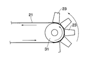
また本発明のシート状体整列搬出装置には、図2の部分側面図及び図3に示すように、コンベアベルト21の幅方向中央部に、送行方向に沿って連続的に、複数の第2仕切板23が設けられている。
【0018】
本発明のシート状体整列搬出装置の動作を以下に説明すれば、図1、製袋された多数の偏平シート状パウチが連続して配列して連なる長尺状のパウチシート、又は長尺状の印刷シートなど長尺シート状体Sを、フィード部Aの対向して一定のフィード速度V1 で回転するニップロール1、2にて水平方向にフィードしながら、カッティングプレート3とカッター刃4との間に送り込む。
【0019】
さらに、送り込まれた長尺シート状体Sの前端部をシート張設部Bの対向して前記速度V1 より僅かに速い回転速度V2 で回転するニップロール5、6の間に導入して、フィード部Aとシート張設部Bとの間の長尺シート状体Sを弛みの無い状態に張設する。
【0020】
その後、直ちに、該ニップロール1、2とニップロール5、6の一旦回転停止動作により、長尺シート状体Sの送行を停止させて、張設状態の長尺シート状体Sをカッター刃4にてカッティングする。
【0021】
カッティング後は、直ちにニップロール1、2とニップロール5、6が回転動作して、長尺シート状体Sがカッティングプレート3とカッター刃4との間にフィードされ、その長尺シート状体S前端部が、ガイドプレート10の上面に沿ってガイドされながら移動してニップロール5、6間に導入されると共に、カッティングされた枚葉シート状体S1 はニップロール5、6により前方に送り出される。
【0022】
そして、ニップロール5、6により前方に送り出された枚葉シート状体S1 は自然落下状態で、搬出コンベア部Cの一旦送行停止中のコンベアベルト21上面に、その枚葉シート状体S1 前端部をコンベア送行方向前方にある第1仕切板22の後側にて降下動作している突揃板12に突き当てられて水平に載置される。
【0023】
上記動作を繰り返すことにより、一定長さにカッティングされた枚葉シート状体S1 が、順次、ニップロール5、6にて送り出され、計数器にて送り出し枚数をカウントされ、一旦送行停止中のコンベアベルト21上に突揃板12に突き当てられて、整列状態で所定枚数(例えば50枚程度)積み重ねられ集積される。
【0024】
なお、枚葉シート状体S1 の送り出し枚数を計数する計数器は、対向配置した投光器7と反射板8との間を通過する枚葉シート状体S1 の通過を検知する通過検知器と、その通過検知信号によりカウント動作するカウンターとにより構成したものでもよいが、例えば、長尺シート状体Sを枚葉シート状体S1 にカッティングするカッター刃4の昇降動作用の駆動回転系統に接続したロータリーエンコーダ又はその駆動回転系統の回転コロやカムなどに周接して設けたリミットスイッチによるカッター刃4の昇降動作サイクル検知器と、その検知器からの1サイクル信号毎にカウントするカウンターとにより構成したものでもよい。
【0025】
所定枚数を検知した計数器からの信号指示により、ニップロール1、2、5、6の回転が一旦停止し、昇降用アクチュエータ11(例えばエアシリンダ)が動作して突揃板12がベルト21上方に上昇動作し、搬出コンベア部Cのコンベアベルト21が送行を開始して、送行方向前側と後側のそれぞれ第1仕切板22、22の間に突揃板12により突き揃えられて集積された枚葉シート状体S1 は、後側の第1仕切板22により押し送りされて前方に搬出される。
【0026】
そして、上方に待機中の突揃板12下端の直下に後側の第1仕切板22近傍の後側が到達した時点で、コンベアベルト21は一旦停止し、突揃板12が下降動作した後に、次の枚葉シート状体S1 の集積が開始され、上記動作を繰り返すことにより、順次、コンベアベルト21上に枚葉シート状体S1 が所定枚数集積されて搬出される。
【0027】
なお、本発明のシート状体整列搬出装置の搬送コンベアCのコンベアベルト21の幅方向の中央部に第2仕切板23を設けた場合には、それに対応して、フィード部Aとシート張設送出部Bとを二列に配置し、コンベアベルト21の幅方向両側に第2仕切板23を挟んで、それぞれ一列ずつ二列に集積して、送行し搬出するものである。
【0028】
【発明の効果】
本発明のシート状体整列搬出装置は、コンベアベルト上に集積された枚葉シート状体が、その前端部を突揃板により良好に突き揃えられ、コンベアベルトの送行時には、突揃板が真上に回避動作し、集積枚葉シート状体の送行方向後側の第1仕切板によって押し送りされるので、たとえ枚葉シート状体S1 の表面が滑り易い材質面であっても、集積された枚葉シート状体S1 の整列状態がコンベアベルトの送行搬出動作によっては崩れることがなく良好な集積と搬出ができる。
【0029】
また、本発明のシート状体整列搬出装置は、コンベアベルトの中央部に沿って設けた第2仕切板により、一列集積方式だけでなく、二列集積方式においても、幅方向に隣接する二列の集積枚葉シート状体S1 が互いに滑って崩れて混じり合うことがなく、二列の仕分け搬出操作と、搬出後の取り分け操作や仕分け操作、梱包操作等の能率の低下を防ぐ効果がある。
【図面の簡単な説明】
【図1】本発明のシート状体整列搬出装置の全体側面図。
【図2】本発明のシート状体整列搬出装置の部分側面図。
【図3】本発明のシート状体整列搬出装置のコンベアベルトの部分平面図。
【図4】従来のシート状体整列搬出装置の全体側面図。
【符号の説明】
A…フィード部 B…シート張設部 C…搬送コンベア
S…長尺シート状体 S1 …枚葉シート状体
1、2…ニップロール 3…カッティングプレート 4…カッター刃
5、6…ニップロール 7…投光器 8…反射板 9a…支軸 9…突揃板
10…ガイドプレート 11…昇降用アクチュエータ 12…突揃板
21…コンベアベルト 22…第1仕切板 23…第2仕切板
31、32…回転体(プーリー)[0001]
TECHNICAL FIELD OF THE INVENTION
The present invention relates to a sheet-like body for cutting a long sheet-like body such as a flat sheet-like pouch or a printing sheet made into a bag into a fixed single sheet form, stacking it in an aligned state, and carrying it out in a block shape. The present invention relates to an aligning / unloading device.
[0002]
[Prior art]
As shown in FIG. 4, a conventional sheet aligning and unloading device for aligning and unloading flattened sheet pouches made of a bag forms a long sheet S at a constant rotational speed in opposition to a feed unit A. The sheet is fed between the cutting plate 3 and the cutter blade 4 while being fed horizontally by the nip rolls 1 and 2 rotating at V1. After being introduced between the nip rolls 5 and 6 rotating at V2 to stretch a long sheet S between the feed section A and the sheet stretching section B without slack, the nip roll 1 is stretched. 2 and the rotation of the nip rolls 5 and 6 are temporarily stopped to stop the feeding of the long sheet S, and the stretched long sheet S is cut by the cutter blade 4.
[0003]
Immediately after the cutting, the nip rolls 1 and 2 and the nip rolls 5 and 6 rotate to feed a long sheet-like body S, and the front end thereof moves along the upper surface of the guide plate 10 and the nip rolls 5 and 6 are moved. And the cut sheet-like sheet S1 is sent forward by the nip rolls 5 and 6, and is naturally dropped on the conveyer belt 21 of the unloading conveyor section C, which has once stopped moving, at its front end. The part is abutted against a butt plate 9 suspended vertically by its own weight on a support shaft 9a located forward in the conveyor transport direction and placed horizontally.
[0004]
By repeating the above operation, the sheet-like sheet S1 cut to a fixed length is sequentially sent out by the nip rolls 5 and 6, and the passage is detected by the counters (the projector 7 and the reflector 8). A predetermined number of sheets (for example, about 50 sheets) are stacked and stacked in an aligned state on the conveyer belt 21 which is temporarily stopped and abutted against the butting plate 9.
[0005]
According to a signal instruction from a counter that has detected a predetermined number of sheets, the conveyer belt 21 of the unloading conveyor section C starts feeding, and pushes the protruding plate 9 forward to open the stacked sheet-like sheets S1. The conveyer belt 21 is temporarily stopped when the lower end of the butting plate 9 is carried out and passes through the upper surface of the stacking sheet S1 and the posture of the butting plate 9 returns to the vertical state, and the next sheet-like sheet is stopped. The stacking of the sheets S1 is started, and by repeating the above operation, a predetermined number of sheet-shaped sheets S1 are sequentially stacked and conveyed on the conveyor belt 21.
[0006]
[Problems to be solved by the invention]
By the way, in the above-mentioned sheet aligning / unloading device, the sheet-like sheet S1 accumulated on the conveyor belt 21 is moved forward by the conveyor belt 21 so that the front end of the sheet-like sheet S1 accumulated on the conveyor S21. When the upper surface and the upper surface are pushed forward while pushing out the butt plate 9, the aligned state of the stacked sheets S1 is easily broken, and the surface of the sheets S1 is particularly slippery. This tends to reduce the efficiency of sorting operations, sorting operations, packing operations, and the like after unloading.
[0007]
SUMMARY OF THE INVENTION An object of the present invention is to solve the above-mentioned disadvantages, and to provide a method of carrying out a sheet while maintaining an aligned state of sheets stacked on a conveyor belt.
[0008]
[Means for Solving the Problems]
The invention according to claim 1 of the present invention provides a feed section A for feeding a long sheet S in a horizontal direction at a speed V1, and a front end of the fed long sheet S to introduce the speed V1. The sheet S is rotated at a slightly higher rotation speed V2 to stretch the sheet S, and the stretched sheet S is sent forward by the cutter blade 4 to feed the sheet S1 after cutting. In the sheet aligning and unloading device including the loading and unloading section B and the unloading and transporting section C for loading, transporting, and unloading the unloaded sheet-like sheet S1, the sheet is disposed above the conveyor belt 21 of the unloading conveyor section C. A protruding plate 12 for abutting the front ends of the sheet-like members S1 and a plurality of first partition plates 22 are provided at equal intervals in the carrying-out direction of the conveyor belt 21. Is sent out and loaded A sheet-like body alignment unloading device, characterized in that at Okugyo direction rear side of the first partition plate 22 of Okugyo direction front loading position of Aberuto 21 provided to the elevating operation.
[0009]
The invention according to claim 2 of the present invention is the sheet aligning / unloading device according to claim 1, wherein a plurality of second partitioning plates are continuously provided along a feeding direction at a central portion in a width direction of the conveyor belt 21. 23 is a sheet-like body aligning and carrying-out device provided with 23.
[0010]
BEST MODE FOR CARRYING OUT THE INVENTION
DETAILED DESCRIPTION OF THE PREFERRED EMBODIMENTS An embodiment of a sheet-like body aligning and carrying-out device of the present invention will be described in detail below. FIG. 1 is a side view of a sheet-like body aligning and carrying-out device of the present invention. And an unloading conveyor section C.
[0011]
The feed section A is constituted by nip rolls 1 and 2 which rotate in opposition to each other, and feeds the long sheet S between the cutting plate 3 and the cutter blade 4 at a feed speed V1 in the horizontal direction.
[0012]
The sheet stretching and feeding section B is constituted by opposed nip rolls 5 and 6 which can be separated or contacted, and is a front end portion of a long sheet S fed between the cutting plate 3 and the cutter blade 4 at a speed V1. After rotating at a rotation speed V2 slightly higher than the feed speed V1, the sheet S is stretched, and the stretched sheet S is cut by the cutter blade 4. The sheet-like sheet S1 is sent forward.
[0013]
The unloading conveyor section C is provided with an endless conveyor belt 21 wound around rotating bodies 32 and 33 (pulleys) at both ends, and one of the rotating bodies is provided with a driving rotation mechanism to carry out round transfer. The predetermined number of sheets (for example, 50 to 100 sheets) of the sheet-like sheets S1 sent out by the nip rolls 5 and 6 are naturally dropped onto the conveyor belt 21 that has once stopped the transfer line, and then sent and carried out. Things.
[0014]
Above the conveyor belt 21 of the unloading conveyor section C, there is provided a butting plate 12 for abutting the front ends of the sheet-like sheets S1 sent out by the nip rolls 5 and 6; Moves downward to such an extent that the lower end of the abutting plate 12 of the conveyor belt 21 once stopped in contact with the upper surface of the belt, and when the conveyor belt 21 is carried out by transportation, the upper surface of the stacked sheet-like sheets S1 The ascending / descending operation is performed using an ascending / descending actuator 11 (for example, an air cylinder).
[0015]
Further, as shown in the side view of FIG. 1 and the plan view of the belt of FIG. 3, the conveyor belt 21 of the unloading conveyor section C is provided with a plurality of first partition plates 22 at equal intervals in the belt transporting and unloading direction. Thus, the sheet S1 stacked on the conveyor belt 21 can be carried out while pushing the rear end thereof.
[0016]
Then, as shown in FIG. 1, the butt plate 12 is fed by the nip rolls 5 and 6 of the conveyor belt 21 in a state where the feeding is stopped, and the upper surface of the belt 21 at the position where the sheet-like sheets S1 are accumulated. The two first partition plates 22 on the front and rear sides in the transport direction are provided to move up and down inside the first partition plate 22 on the front side in the transport direction.
[0017]
Further, as shown in the partial side view of FIG. 2 and FIG. 3, the sheet-like body aligning and unloading device of the present invention has a plurality of A partition plate 23 is provided.
[0018]
The operation of the sheet-shaped body aligning and carrying-out device of the present invention will be described below. FIG. 1 shows a long pouch sheet or a long pouch sheet in which a large number of flat sheet pouches formed in a bag are continuously arranged and connected. Between the cutting plate 3 and the cutter blade 4 while horizontally feeding a long sheet-like material S such as a printing sheet with the nip rolls 1 and 2 rotating at a constant feed speed V1 opposite the feed section A. Send to
[0019]
Further, the front end of the fed long sheet S is introduced between the nip rolls 5 and 6 which rotate at a rotation speed V2 slightly higher than the above-mentioned speed V1 opposite to the sheet stretching portion B and feed portion. A long sheet-like body S between A and the sheet stretching portion B is stretched without slack.
[0020]
Then, immediately, by temporarily stopping rotation of the nip rolls 1 and 2 and the nip rolls 5 and 6, the feeding of the long sheet S is stopped, and the stretched long sheet S is cut by the cutter blade 4. Cutting.
[0021]
Immediately after the cutting, the nip rolls 1 and 2 and the nip rolls 5 and 6 rotate, and the long sheet S is fed between the cutting plate 3 and the cutter blade 4, and the front end of the long sheet S is fed. Is moved while being guided along the upper surface of the guide plate 10 and is introduced between the nip rolls 5 and 6, and the cut sheet-like sheet material S 1 is fed forward by the nip rolls 5 and 6.
[0022]
Then, the sheet-like sheet S1 sent forward by the nip rolls 5 and 6 is naturally dropped, and the front end of the sheet-like sheet S1 is placed on the upper surface of the conveyor belt 21 which has been temporarily stopped in the unloading conveyor section C. At the rear side of the first partition plate 22 located in front of the conveyor transport direction, it is abutted against the descending butting plate 12 that is moving downward and is placed horizontally.
[0023]
By repeating the above operation, the sheet-like sheets S1 cut to a fixed length are sequentially sent out by the nip rolls 5 and 6, the number of sheets sent out is counted by the counter, and the conveyor belt once stopped feeding is stopped. A predetermined number of sheets (for example, about 50 sheets) are stacked on each other and abutted against the butting plate 12 in an aligned state.
[0024]
The counter for counting the number of sheets S1 sent out is a passage detector for detecting the passage of the sheet S1 passing between the light projector 7 and the reflector 8 disposed opposite to each other. A counter configured to perform a counting operation based on the passage detection signal may be used. For example, a rotary connected to a drive rotation system for raising and lowering a cutter blade 4 that cuts a long sheet S into a single sheet S1. It consists of a detector for raising and lowering the cutter blade 4 by a limit switch provided in contact with the rotary roller or cam of the encoder or its driving rotary system, and a counter for counting each cycle signal from the detector. May be.
[0025]
The rotation of the nip rolls 1, 2, 5, and 6 is temporarily stopped by a signal instruction from the counter that has detected the predetermined number of sheets, and the elevation actuator 11 (for example, an air cylinder) operates to move the butting plate 12 above the belt 21. Ascending operation, the conveyor belt 21 of the unloading conveyor section C starts feeding, and sheets stacked by the butting plate 12 between the first partitioning plates 22 on the front side and the rear side in the feeding direction, respectively. The leaf sheet S1 is pushed forward by the first partitioning plate 22 on the rear side and is carried out forward.
[0026]
Then, when the rear side near the rear first partition plate 22 arrives immediately below the lower end of the butt plate 12 waiting on the upper side, the conveyor belt 21 temporarily stops, and after the butt plate 12 descends, The accumulation of the next single sheet S1 is started, and by repeating the above operation, a predetermined number of single sheets S1 are sequentially accumulated on the conveyor belt 21 and carried out.
[0027]
When the second partition plate 23 is provided at the center in the width direction of the conveyor belt 21 of the conveyor C of the sheet-shaped body aligning and unloading device of the present invention, the feed portion A and the sheet stretching member are correspondingly provided. The delivery units B are arranged in two rows, and are stacked in two rows, one row at a time, with the second partition plate 23 sandwiched on both sides in the width direction of the conveyor belt 21, and then sent and carried out.
[0028]
【The invention's effect】
According to the sheet-shaped body aligning and carrying-out device of the present invention, the sheet-like sheets stacked on the conveyor belt have their front ends satisfactorily butted by a butting plate. Since the sheet S1 moves upward and is pushed forward by the first partition plate on the rear side in the feeding direction of the stacked sheet-like material, the sheet-like material S1 is stacked even if the surface thereof is a slippery material. Good stacking and unloading can be performed without disturbing the alignment of the sheet-like sheets S1 by the transporting and unloading operation of the conveyor belt.
[0029]
In addition, the sheet-shaped body aligning / unloading device of the present invention can be configured such that the second partitioning plate provided along the central portion of the conveyor belt allows not only the single-row stacking method but also the two-row Are prevented from slipping and collapsing with each other, and there is an effect of preventing a decrease in the efficiency of the sorting and carrying out operations in two rows and the sorting, sorting and packing operations after carrying out.
[Brief description of the drawings]
FIG. 1 is an overall side view of a sheet aligning / unloading device of the present invention.
FIG. 2 is a partial side view of the sheet-like body aligning / unloading device of the present invention.
FIG. 3 is a partial plan view of a conveyor belt of the sheet-like body aligning and carrying-out device of the present invention.
FIG. 4 is an overall side view of a conventional sheet aligning and discharging device.
[Explanation of symbols]
A: Feeding part B: Sheet stretching part C: Conveyor S: Long sheet S1: Single sheet 1, 2, Nip roll 3, Cutting plate 4, Cutter blade 5, 6, Nip roll 7, Floodlight 8 ... Reflecting plate 9a ... Support shaft 9 ... Protruding plate 10 ... Guide plate 11 ... Elevating actuator 12 ... Protruding plate 21 ... Conveyor belt 22 ... First partition plate 23 ... Second partition plate 31, 32 ... Rotating body (pulley) )