【0001】
【発明の属する技術分野】
本発明は、プレス加工に供するブランク材を剪断等によって板材から切り出すブランク材製造装置に関する。
【0002】
【従来の技術】
一般に、車体のパネル等に用いられるプレス成形品は、平板状のブランク材をプレス加工することにより製造される。この種の加工を行うプレス装置においては、一般に、プレス成形用金型に隣接してブランクホルダが設けられている。そして、プレス装置では、ブランク材の縁辺部に設定された非加工領域をブランクホルダによって保持することにより、プレス加工時の応力によるプレス成形品へのしわの発生を防止している。
【0003】
ところで、このようなプレス加工に供するブランク材は、通常、展伸材コイル等から供給される板材を、周知の剪断機(例えば、特許文献1参照)等を備えたブランク材製造装置を用いて所定に切り出すことにより形成される。この場合、板材の利用効率を向上させてプレス成形品の歩留まりを向上させるため、ブランク材に設定される非加工領域を可能な限り小さくすることが望ましい。
【0004】
【特許文献1】
実開昭59−39125号公報
【0005】
【発明が解決しようとする課題】
しかしながら、ブランク材の非加工領域を縮小するには限界がある。すなわち、非加工領域を必要以上に縮小すると、ブランクホルダによるブランク材の保持が不十分となり、プレス成形品にしわが発生する等して、却って歩留まりの低下を招く虞がある。
【0006】
本発明は上記事情に鑑みてなされたもので、ブランク材を効率よく切り出してプレス成形品の歩留まりを向上させることのできるブランク材製造装置を提供することを目的とする。
【0007】
【課題を解決するための手段】
上記課題を解決するため、請求項1記載の発明は、プレス加工に供するブランク材を板材から切り出すブランク材製造装置において、上記切り出しによって上記ブランク材の縁辺部に設定される非加工領域の少なくとも一部に櫛歯形状の凹凸部を形成する刃部を備えたことを特徴とする。
【0008】
また、請求項2記載の発明によるブランク材製造装置は、請求項1記載の発明において、上記刃部は、上記凹凸部を、上記ブランク材の加工領域に沿う方向に対して所定の傾斜角を有する櫛歯形状に切り出すことを特徴とする。
【0009】
また、請求項3記載の発明によるブランク材製造装置は、請求項1または請求項2記載の発明において、上記刃部は、上記凹凸部を、上記板材からの切り出しと同時に板厚方向に曲げ成形することを特徴とする。
【0010】
【発明の実施の形態】
以下、図面を参照して本発明の実施の形態を説明する。図面は本発明の第1の実施の形態に係わり、図1は剪断機の要部縦断面図、図2は図1のI−I断面図、図3はブランク材製造装置及びプレス装置の概略構成図、図4はブランク材の平面図、図5はプレス装置にブランク材を保持した状態を示す要部縦面図、図6はブランク材のプレス加工時のプレス装置を示す要部縦断面図、図7はプレス成形品を示す平面図である。
【0011】
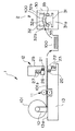
図3において、符号1は展伸材コイル101からブランク材100を切り出し形成するブランク材製造装置を示し、符号2はブランク材製造装置1で形成されたブランク材100をプレス加工するプレス装置を示す。
【0012】
ブランク材製造装置1は、展伸材コイル101をテーブル13上に回転自在に軸支する支持部10と、図示しないガイドロールによって展伸材コイル101からテーブル面13aに沿って供給される板材101aの巻き癖等を矯正するレベラー11と、レベラー11で平板状に矯正された板材101aを剪断してブランク材100を切り出す剪断機12とを有して要部が構成されている。
【0013】
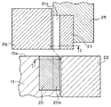
図1、図3に示すように、剪断機12は、テーブル13に固設された下刃20と、この下刃20に対して昇降移動する上刃21とを有して構成されている。
【0014】
下刃20はテーブル面13aの下流端に固設されるもので、この下刃20の下流側には、上刃21に対向する下押え刃22が併設されている。下押え刃22は、油圧シリンダ23を介してテーブル13に支持され、板材101aの剪断時に下降される上刃21との間に板材101aを弾性的に挟持することで板材101aを保持するようになっている。
【0015】
上刃21は、図示しないシリンダ等を介してテーブル13に相対して昇降移動されるラム25の下端部に固設されるもので、この上刃21の上流側には、下刃20に対向する上押え刃26が併設されている。上押え刃26は、油圧シリンダ27を介してラム25に支持され、板材101aの剪断時に上刃21とともに下降して、下刃20との間に板材101aを弾性的に挟持することで板材101aを保持するようになっている。
【0016】
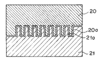
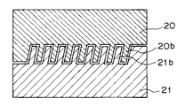
ここで、図2に示すように、下刃20の刃部20aは、櫛歯形状の凹凸をなす刃部で構成されている。一方、上刃21の刃部21aは、下刃20の刃部20aに噛合する櫛歯形状の凹凸をなす刃部で構成されている。そして、これら下刃20及び上刃21は、板材101aからブランク材100を切り出す際に、刃部20a,21aによって、ブランク材100の長手方向縁辺部に櫛歯形状の凹凸部100c(後述する)を形成するようになっている。
【0017】
このように構成されたブランク材製造装置1は、展伸材コイル101から供給される板材101aを所定長さ毎に切り出すことによってブランク材100を形成する。すなわち、図示しないガイドロールによって板材101aが剪断機12に所定長さ進入されると、剪断機12は、ラム25を下降させることによって、下押え刃22と上刃21との間に板材101aを挟持するとともに、上押え刃26と下刃20との間に板材101aを挟持し、挟持した板材101aを刃部20a,21a間で剪断することによりブランク材100を形成する。
【0018】
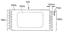
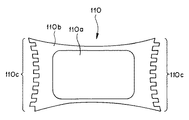
図4に示すように、形成されたブランク材100は、その中央が加工領域100aとして設定されているとともに、その周部(ブランク材100の縁辺部)が非加工領域100bとして設定されている。さらに、このブランク材100は、非加工領域100bのうち、板材101aからの切り出しによって形成された長手方向両端の縁辺部に、刃部20a,21aに対応する櫛歯形状の凹凸部100cが形成される。本実施の形態において、凹凸部100cは、その深さが例えば10(mm)に設定されており、その凹部及び凸部の各幅が例えば7(mm)に設定されている。なお、凹凸部100cは、各凸部の基部及び先端部が、例えばR=2〜3(mm)の円弧状に形成されるものであってもよい。
【0019】
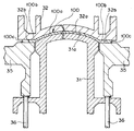
図3、図5及び図6に示すように、プレス装置2は、支持枠30に固設された成形用下側金型31と、この成形用下側金型31に相対して昇降移動する成形用上側金型32とを有して構成されている。
【0020】
成形用下側金型31は、ブランク材100の加工領域100aに対応する所望形状の成形面31aを頂面に有する金型で構成されている。また、成形用下側金型31の両側には、ブランク材100の長手方向両端に設定された非加工領域100bに対応するパンチ35がそれぞれ併設され、各パンチ35はクッションピン36を介して支持枠30に支持されている。
【0021】
成形用上側金型32は、図示しないシリンダ等を介して支持枠30に支持されることにより、成形用下側金型31に相対して昇降移動される。この成形用上側金型32の底面には、成形用下側金型31の成形面31aに対応する成形面32aが形成されているとともに、各パンチ35に対応するパンチ受け面32bが成形面32aと一体に形成されている。
【0022】
そして、このように構成されたプレス装置2は、ブランク材100が搬入された後に、成形用上側金型32を下降させることによって、加工領域100aにプレス加工を施し、図7に示すプレス成形品110を得る。すなわち、プレス装置2は、先ず、成形用上側金型32を所定位置まで下降させることによって、ブランク材100の長手方向両端縁辺部(凹凸部100cを有する非加工領域100b)をパンチ35とパンチ受け面32bとの間に挟持し、この状態で、成形用上側金型32をさらに下降させることによって、ブランク材100の加工領域100aに、成形面31a,31bを用いたプレス成形を施す。
【0023】
このようなプレス成形によってブランク材100からプレス成形品110が形成され、図7に示すように、プレス成形品110の中央には、所望形状のプレス成形部110aが形成される。その際、プレス成形部110a周部の非加工領域110bは、プレス加工時に、凹凸部110cを含む長手方向両端が各パンチ35及びパンチ受け面32bによって挟持されることにより、過大な変形が抑制される。そして、この非加工領域110bに対する変形の抑制によって、プレス成形部110aにしわが発生することが防止される。
【0024】
このような実施の形態によれば、ブランク材100の縁辺部に設定された非加工領域100bに櫛歯形状の凹凸部100cを形成することにより、板材101aから順次切り出されるブランク材100間で非加工領域100bに必要な材料の一部を共用することができる。
【0025】
従って、ブランク材100の形成に必要な板材101aの歩留まりを向上させることができる。同時に、プレス加工に必要な非加工領域100bの長さを凹凸部100cによって十分に確保することができるので、パンチ35とパンチ受け面32bとの間に非加工領域100bを強固に保持することができ、プレス成形品110に懸念されるしわの発生等を効果的に抑制することができる。換言すれば、板材101aの使用効率向上による歩留まりの向上と、プレス成形品110自体の歩留まりの向上とを同時に実現することができる。
【0026】
次に、図8は本発明の第2の実施の形態に係わり、図8は図1のI−I断面図である。なお、本実施の形態においては、下刃20及び上刃21の刃部形状が上述の第1の実施の形態と異なる。なお、その他、同様の構成については同符号を付して説明を省略する。
【0027】
図8に示すように、下刃20の刃部20bは、櫛歯形状の凹凸をなす刃部で構成され、各櫛歯形状の凹凸は板材101aの剪断方向に対して所定の傾斜角で傾斜されている。一方、上刃21の刃部21bは、下刃20の刃部20bに噛合する櫛歯形状の凹凸をなす刃部で構成されている。そして、これら下刃20及び上刃21は、板材101aからブランク材100を切り出す際に、刃部20b,21bによって、ブランク材100の加工領域100aに沿う方向に対して所定の傾斜角を有する櫛歯形状の凹凸部100cを、ブランク材100の長手方向縁辺部(非加工領域100b)に形成するようになっている。
【0028】
このような実施の形態においては、上述の第1の実施の形態と同様に、ブランク材100の長手方向両端縁辺部(傾斜された凹凸部100cを有する非加工領域100b)をパンチ35とパンチ受け面32bとの間に挟持した状態でプレス加工が行われるが、その際、加工領域100a方向への応力によって、凹凸部100cは、その傾斜が修正される方向に変形される(回転される)。そして、この変形により、凹凸部100cの長さは実質的に長大化されるので、その分、非加工領域100bを拡張することができ、パンチ35とパンチ受け面32bとの間にブランク材100を強固に保持することができる。
【0029】
次に、図9,図10は本発明の第3の実施の形態に係わり、図9は剪断機の要部縦断面図、図10(a)はブランク材の平面図であって(b)はブランク材の側面図である。なお、本実施の形態においては、下刃20及び上刃21の刃部形状が上述の第1の実施の形態と異なる。なお、その他、同様の構成については同符号を付して説明を省略する。
【0030】
図9に示すように、下刃20の刃部20aの頂面には、脈動形状をなす成形面20cが形成されている。一方、上刃21の刃部21aの底面には、成形面20cに対応する脈動形状をなす成形面21cが形成されている。そして、これら下刃20及び上刃21は、板材101aからブランク材100を切り出す際に、刃部20a,21aによって、ブランク材100の長手方向縁辺部(非加工領域100b)に櫛歯形状の凹凸部100dを形成すると同時に、成形面20c,21cによって、各凹凸部100dを板厚方向に曲げ形成するようになっている(図10参照)。
【0031】
このような実施の形態においては、上述の第1の実施の形態と同様に、ブランク材100の長手方向両端縁辺部(凹凸部100dを有する非加工領域100b)をパンチ35とパンチ受け面32bとの間に挟持した状態でプレス加工が行われるが、その際、パンチ35とパンチ受け面32bによる挟持によって、板厚方向に曲げ形成された凹凸部100dの脈動形状が平板状に変形される。そして、この変形により、凹凸部100dの長さは実質的に長大化されるので、その分、非加工領域100bを拡張することができ、パンチ35とパンチ受け面32bとの間にブランク材100を強固に保持することができる。
【0032】
なお、上述の各実施の形態においては、ブランク材の長手方向縁辺部に設定された非加工領域に凹凸部を形成する構成の一例について説明したが、本発明はこれに限定されるものではなく、他の非加工領域に凹凸部を形成してもよいことは勿論である。また、上述した各実施の形態による構成を適宜組み合わせてもよいことは勿論である。
【0033】
【発明の効果】
以上説明したように本発明によれば、非加工領域を十分に確保したまま、板材からブランク材を効率よく切り出すことができ、プレス成形品の歩留まりを向上させることができる。
【図面の簡単な説明】
【図1】本発明の第1の実施の形態に係わり、剪断機の要部縦断面図
【図2】同上、I−I断面図
【図3】同上、ブランク材製造装置及びプレス装置の概略構成図
【図4】同上、ブランク材の平面図
【図5】同上、プレス装置にブランク材を保持した状態を示す要部縦面図
【図6】同上、ブランク材のプレス加工時のプレス装置を示す要部縦断面図
【図7】同上、プレス成形品を示す平面図
【図8】本発明の第2の実施の形態に係わり、図1のI−I断面図
【図9】本発明の第3の実施の形態に係わり、剪断機の要部縦断面図
【図10】同上、(a)はブランク材の平面図であって(b)はブランク材の側面図
【符号の説明】
1 … ブランク材製造装置
12 … 剪断機
20 … 下刃
20a … 刃部
20b … 刃部
20c … 成形面
21 … 上刃
21a … 刃部
21b … 刃部
21c … 成形面
100 … ブランク材
100b … 非加工領域
100c … 凹凸部
100d … 凹凸部
101a … 板材[0001]
TECHNICAL FIELD OF THE INVENTION
The present invention relates to a blank material manufacturing apparatus that cuts a blank material to be subjected to press working from a plate material by shearing or the like.
[0002]
[Prior art]
In general, a press-formed product used for a panel of a vehicle body or the like is manufactured by pressing a flat blank material. In a press apparatus that performs this type of processing, a blank holder is generally provided adjacent to a press molding die. In the press device, the non-processed area set at the edge of the blank material is held by the blank holder, thereby preventing wrinkles from being generated in the press-formed product due to stress during press working.
[0003]
By the way, the blank material to be subjected to such press working is usually prepared by converting a plate material supplied from a wrought material coil or the like using a blank material manufacturing apparatus equipped with a well-known shearing machine (for example, see Patent Document 1). It is formed by cutting out in a predetermined manner. In this case, in order to improve the utilization efficiency of the plate material and improve the yield of the press-formed product, it is desirable that the non-machining region set in the blank material be as small as possible.
[0004]
[Patent Document 1]
JP-A-59-39125 [0005]
[Problems to be solved by the invention]
However, there is a limit in reducing the non-processed area of the blank material. That is, if the non-processed area is reduced more than necessary, the holding of the blank material by the blank holder becomes insufficient, and wrinkles may be generated in the press-formed product, which may rather lower the yield.
[0006]
The present invention has been made in view of the above circumstances, and an object of the present invention is to provide a blank material manufacturing apparatus capable of efficiently cutting out a blank material and improving the yield of a press-formed product.
[0007]
[Means for Solving the Problems]
In order to solve the above-mentioned problem, an invention according to claim 1 is a blank material manufacturing apparatus that cuts a blank material to be subjected to press working from a plate material, wherein at least one of the non-machining regions set at the edge of the blank material by the cutting is provided. The portion is provided with a blade portion for forming a comb-shaped uneven portion.
[0008]
Further, in the blank material manufacturing apparatus according to the second aspect of the present invention, in the first aspect of the present invention, the blade portion may be configured to set the uneven portion at a predetermined inclination angle with respect to a direction along a processing region of the blank material. It is characterized in that it is cut out into a comb shape.
[0009]
According to a third aspect of the present invention, in the blank material manufacturing apparatus according to the first or second aspect, the blade portion bends the uneven portion in the thickness direction at the same time as cutting out the uneven portion from the plate material. It is characterized by doing.
[0010]
BEST MODE FOR CARRYING OUT THE INVENTION
Hereinafter, embodiments of the present invention will be described with reference to the drawings. The drawings relate to a first embodiment of the present invention. FIG. 1 is a longitudinal sectional view of a main part of a shearing machine, FIG. 2 is a sectional view taken along line II of FIG. 1, and FIG. FIG. 4 is a plan view of a blank material, FIG. 5 is a vertical view of a main part showing a state in which the blank material is held in a press device, and FIG. FIG. 7 is a plan view showing a press-formed product.
[0011]
In FIG. 3, reference numeral 1 denotes a blank material manufacturing apparatus that cuts out and forms a blank material 100 from the wrought material coil 101, and reference numeral 2 denotes a press device that presses the blank material 100 formed by the blank material manufacturing apparatus 1. .
[0012]
The blank material manufacturing apparatus 1 includes a support portion 10 that rotatably supports a wrought material coil 101 on a table 13 and a plate material 101a supplied from the wrought material coil 101 along a table surface 13a by a guide roll (not shown). The main part includes a leveler 11 for correcting the curl and the like, and a shearing machine 12 for cutting the blank 101 by shearing the plate 101a corrected by the leveler 11 into a flat shape.
[0013]
As shown in FIGS. 1 and 3, the shearing machine 12 includes a lower blade 20 fixed to a table 13 and an upper blade 21 that moves up and down with respect to the lower blade 20.
[0014]
The lower blade 20 is fixed to the downstream end of the table surface 13a, and a lower presser blade 22 facing the upper blade 21 is provided downstream of the lower blade 20. The lower presser blade 22 is supported by the table 13 via a hydraulic cylinder 23, and holds the plate 101a by elastically holding the plate 101a between the lower blade 22 and the upper blade 21 that is lowered when the plate 101a is sheared. Has become.
[0015]
The upper blade 21 is fixed to the lower end of a ram 25 which is moved up and down relative to the table 13 via a cylinder or the like (not shown). The upper holding blade 26 is provided in parallel. The upper presser blade 26 is supported by the ram 25 via the hydraulic cylinder 27 and descends together with the upper blade 21 when the plate 101a is sheared, thereby elastically holding the plate 101a between the lower blade 20 and the plate 101a. Is to be held.
[0016]
Here, as shown in FIG. 2, the blade portion 20a of the lower blade 20 is configured by a blade portion having irregularities in a comb shape. On the other hand, the blade portion 21a of the upper blade 21 is configured by a blade portion having comb-shaped irregularities meshing with the blade portion 20a of the lower blade 20. When cutting the blank material 100 from the plate material 101a, the lower blade 20 and the upper blade 21 are comb-shaped uneven portions 100c (to be described later) on the edges in the longitudinal direction of the blank material 100 by the blade portions 20a and 21a. Is formed.
[0017]
The blank material manufacturing apparatus 1 configured as described above forms the blank material 100 by cutting the plate material 101a supplied from the wrought material coil 101 into predetermined lengths. That is, when the plate material 101a is advanced into the shearing machine 12 by a predetermined length by a guide roll (not shown), the shearing machine 12 lowers the ram 25, thereby moving the plate material 101a between the lower holding blade 22 and the upper blade 21. The blank material 100 is formed by sandwiching the plate material 101a between the upper holding blade 26 and the lower blade 20 and shearing the sandwiched plate material 101a between the blade portions 20a and 21a.
[0018]
As shown in FIG. 4, the formed blank material 100 has its center set as a processing region 100a, and its periphery (the edge of the blank material 100) set as a non-processing region 100b. Further, in the blank material 100, comb-shaped uneven portions 100c corresponding to the blade portions 20a and 21a are formed on the edges at both ends in the longitudinal direction formed by cutting out from the plate material 101a in the non-processed region 100b. You. In the present embodiment, the depth of the uneven portion 100c is set to, for example, 10 (mm), and the width of each of the concave portion and the convex portion is set to, for example, 7 (mm). In addition, as for the uneven | corrugated part 100c, the base part and front-end | tip part of each convex part may be formed in circular arc shape of R = 2-3 (mm), for example.
[0019]
As shown in FIGS. 3, 5 and 6, the press device 2 moves up and down relative to the lower molding die 31 fixed to the support frame 30 and the lower molding die 31. And an upper mold 32 for molding.
[0020]
The lower molding die 31 is configured by a die having a molding surface 31a of a desired shape corresponding to the processing area 100a of the blank material 100 on the top surface. Further, on both sides of the lower mold 31 for forming, punches 35 corresponding to the non-machining areas 100b set at both ends in the longitudinal direction of the blank material 100 are provided in parallel, and each punch 35 is supported via a cushion pin 36. It is supported by the frame 30.
[0021]
The upper molding die 32 is moved up and down relative to the lower molding die 31 by being supported by the support frame 30 via a cylinder (not shown) or the like. A molding surface 32a corresponding to the molding surface 31a of the molding lower die 31 is formed on the bottom surface of the molding upper mold 32, and a punch receiving surface 32b corresponding to each punch 35 is formed on the molding surface 32a. And are integrally formed.
[0022]
Then, the press device 2 configured as described above presses the processing area 100a by lowering the upper molding die 32 after the blank material 100 is carried in, and press-processes the press-formed product shown in FIG. Obtain 110. That is, the pressing device 2 first lowers the upper mold 32 for molding to a predetermined position, so that the both ends in the longitudinal direction of the blank material 100 (the non-processed area 100b having the uneven portion 100c) are received by the punch 35 and the punch receiving portion. By pressing the upper mold 32 further down in this state, the working area 100a of the blank material 100 is subjected to press molding using the molding surfaces 31a and 31b.
[0023]
A press-formed product 110 is formed from the blank material 100 by such press-forming, and a press-formed portion 110a having a desired shape is formed at the center of the press-formed product 110 as shown in FIG. At this time, in the non-processed area 110b around the press-formed portion 110a, excessive deformation is suppressed by press-pressing both ends in the longitudinal direction including the concave and convex portions 110c between the punches 35 and the punch receiving surfaces 32b. You. Then, by suppressing the deformation of the non-processed region 110b, the generation of wrinkles in the press-formed portion 110a is prevented.
[0024]
According to such an embodiment, by forming the comb-teeth-shaped uneven portion 100c in the non-processed region 100b set at the edge of the blank material 100, the non-processed portion between the blank materials 100 sequentially cut from the plate material 101a is formed. Some of the materials required for the processing region 100b can be shared.
[0025]
Therefore, the yield of the plate material 101a required for forming the blank material 100 can be improved. At the same time, the length of the non-processed area 100b required for press working can be sufficiently ensured by the concave and convex portions 100c, so that the non-processed area 100b can be firmly held between the punch 35 and the punch receiving surface 32b. As a result, it is possible to effectively suppress the occurrence of wrinkles and the like which are concerned about the press-formed product 110. In other words, it is possible to simultaneously improve the yield by improving the use efficiency of the plate material 101a and the yield of the press-formed product 110 itself.
[0026]
Next, FIG. 8 relates to a second embodiment of the present invention, and FIG. 8 is a sectional view taken along the line II of FIG. Note that, in the present embodiment, the shapes of the blade portions of the lower blade 20 and the upper blade 21 are different from those of the above-described first embodiment. In addition, the same reference numerals are given to other similar configurations, and description thereof will be omitted.
[0027]
As shown in FIG. 8, the blade portion 20b of the lower blade 20 is constituted by a blade portion having irregularities in a comb shape, and the irregularities in each comb shape are inclined at a predetermined inclination angle with respect to the shear direction of the plate material 101a. Have been. On the other hand, the blade portion 21b of the upper blade 21 is formed of a comb-shaped uneven portion that meshes with the blade portion 20b of the lower blade 20. When cutting the blank material 100 from the plate material 101a, the lower blade 20 and the upper blade 21 have a comb having a predetermined inclination angle with respect to a direction along the processing area 100a of the blank material 100 by the blade portions 20b and 21b. The tooth-shaped uneven portion 100c is formed on the edge of the blank 100 in the longitudinal direction (non-processed area 100b).
[0028]
In such an embodiment, similarly to the above-described first embodiment, the both ends in the longitudinal direction of the blank material 100 (the non-processed area 100b having the inclined concave and convex portions 100c) are punched with the punch 35. Pressing is performed in a state of being sandwiched between the surface 32b and the surface 32b. At this time, the uneven portion 100c is deformed (rotated) by a stress in the direction of the processing region 100a in a direction in which the inclination is corrected. . Since the length of the concave and convex portions 100c is substantially increased by this deformation, the non-processed area 100b can be extended by that much, and the blank material 100 can be inserted between the punch 35 and the punch receiving surface 32b. Can be held firmly.
[0029]
Next, FIGS. 9 and 10 relate to a third embodiment of the present invention. FIG. 9 is a longitudinal sectional view of a main part of a shearing machine, and FIG. Is a side view of the blank material. Note that, in the present embodiment, the shapes of the blade portions of the lower blade 20 and the upper blade 21 are different from those of the above-described first embodiment. In addition, the same reference numerals are given to other similar configurations, and description thereof will be omitted.
[0030]
As shown in FIG. 9, a pulsating forming surface 20c is formed on the top surface of the blade portion 20a of the lower blade 20. On the other hand, on the bottom surface of the blade portion 21a of the upper blade 21, a forming surface 21c having a pulsating shape corresponding to the forming surface 20c is formed. When the lower blade 20 and the upper blade 21 cut out the blank 100 from the plate 101a, the blade portions 20a and 21a cause the comb-shaped irregularities to be formed on the longitudinal edges (non-processed areas 100b) of the blank 100. Simultaneously with the formation of the portion 100d, each of the concavo-convex portions 100d is bent and formed in the thickness direction by the molding surfaces 20c and 21c (see FIG. 10).
[0031]
In such an embodiment, similarly to the above-described first embodiment, the both ends of the blank material 100 in the longitudinal direction (the non-processed area 100b having the uneven portion 100d) are formed by the punch 35 and the punch receiving surface 32b. Pressing is performed in a state of being sandwiched between the holes, and at this time, the pulsation shape of the uneven portion 100d bent and formed in the thickness direction is deformed into a flat plate shape by the sandwiching between the punch 35 and the punch receiving surface 32b. Then, since the length of the uneven portion 100d is substantially increased by this deformation, the non-processed area 100b can be extended by that much, and the blank material 100b is inserted between the punch 35 and the punch receiving surface 32b. Can be held firmly.
[0032]
In each of the above-described embodiments, an example of the configuration in which the uneven portion is formed in the non-processed region set at the longitudinal edge of the blank material has been described, but the present invention is not limited thereto. Of course, uneven portions may be formed in other non-processed regions. Also, it goes without saying that the configurations according to the above-described embodiments may be appropriately combined.
[0033]
【The invention's effect】
As described above, according to the present invention, it is possible to efficiently cut a blank material from a plate material while sufficiently securing a non-processed area, and to improve the yield of press-formed products.
[Brief description of the drawings]
FIG. 1 is a longitudinal sectional view of a main part of a shearing machine according to a first embodiment of the present invention. FIG. 2 is a sectional view taken along a line II in FIG. Configuration diagram [FIG. 4] Same as above, plan view of blank material. [FIG. 5] Same as above, vertical view of main part showing a state where blank material is held in a press device. [FIG. 6] Same as above, press device at the time of press working of blank material. FIG. 7 is a plan view showing a press-formed product according to the second embodiment of the present invention. FIG. 8 is a sectional view taken along line II of FIG. 1 according to the second embodiment of the present invention. FIG. 10 is a plan view of a blank material, and FIG. 10B is a plan view of a blank material, and FIG. 10B is a side view of the blank material according to the third embodiment.
DESCRIPTION OF SYMBOLS 1 ... Blank material manufacturing apparatus 12 ... Shearer 20 ... Lower blade 20a ... Blade part 20b ... Blade part 20c ... Molding surface 21 ... Upper blade 21a ... Blade part 21b ... Blade part 21c ... Molding surface 100 ... Blank material 100b ... Non-processing Area 100c Uneven part 100d Uneven part 101a Plate