JP2004187357A - Grommet - Google Patents
Grommet Download PDFInfo
- Publication number
- JP2004187357A JP2004187357A JP2002348857A JP2002348857A JP2004187357A JP 2004187357 A JP2004187357 A JP 2004187357A JP 2002348857 A JP2002348857 A JP 2002348857A JP 2002348857 A JP2002348857 A JP 2002348857A JP 2004187357 A JP2004187357 A JP 2004187357A
- Authority
- JP
- Japan
- Prior art keywords
- diameter
- small
- wire harness
- grommet
- diameter tube
- Prior art date
- Legal status (The legal status is an assumption and is not a legal conclusion. Google has not performed a legal analysis and makes no representation as to the accuracy of the status listed.)
- Granted
Links
Images


Abstract
Description
【0001】
【発明の属する技術分野】
本発明はグロメットに関し、詳しくは、自動車に配索するワイヤハーネスに組みつけて、車体パネルの貫通穴に一方向から押し込んで装着するワンモーショングロメットであって、貫通穴の挿通部分におけるワイヤハーネスの保護および防水、防塵を図るものである。
【0002】
【従来の技術】
従来、自動車のエンジンルームから車室内へ配索されるワイヤハーネスにはグロメットを装着して、エンジンルームと車室とを仕切る車体パネルの貫通穴にグロメットを取り付けて、貫通穴を通るワイヤハーネスの保護およびエンジンルーム側から車室への防水、防塵、遮音を図っている。
【0003】
この種のグロメットとして、本出願人は先に特開平2002−171645号公報で図14(A)(B)に示すようなグロメットを含め多数のグロメットを提供している。
図14に示すグロメット1は、拡径筒部2と、該拡径筒部2の小径側に連続する小径筒部3を備え、該拡径筒部2の大径側に車体係止凹部4を設け、車体係止凹部4の溝4aを挟む両側壁は、大径側が垂直壁4bで、対向する小径側は傾斜壁4cとし、該拡径筒部2の外表面には複数の突条部2aを傾斜壁先端から小径筒部3との連結側まで放射状に突設している。該グロメット1に対してワイヤハーネスW/Hを小径筒部3から拡径筒部2の中空部を通して貫通し、小径筒部3の先端側でテープTにより固着している。
【0004】
車体パネルPの貫通穴Hへの装着作業は、エンジンルーム側の室外からグロメット1の小径筒部3を貫通穴Hに挿入し、拡径筒部2が貫通穴Hの内周面に接触した時点から力を入れた押し込んで拡径筒部2を内方に潰すように変形させて貫通穴を通過させ、通過後に復帰する傾斜壁4cと垂直壁4bとを車体パネルPの両面に密着させて、グロメット1の車体係止凹部4を車体パネルPの貫通穴に装着している。該グロメット1の貫通穴へのワンモーションによる装着作業時に突条部2aが貫通穴Hの内周縁に接触し、拡径筒部2の外表面全体が接触する場合より接触面積を低減することにより挿入抵抗を低減して装着作業性を高めている。かつ、貫通穴Hへの取付後においては、ワイヤハーネスにエンジンルーム方向への引張力が作用しても、突条部2aの先端が小径筒部3の外周面に圧接して小径筒部3の移動を抑制し、グロメット1の車体係止凹部4が貫通穴Hから外れることを防止し、グロメットの保持力を強めている。
【0005】
【特許文献1】
特開平2002−171645号公報
【0006】
【発明が解決しようとする課題】
上記図14に示すワンモーションのグロメット1は、車体パネルの貫通穴への装着作業性が良いと共に、貫通穴への取付後の保持力も高い利点を有するが、該グロメット1を貫通するワイヤハーネスW/Hの電線群の間に予め止水剤5を充填して線間止水部Aを設けたものを貫通させる場合には改良の余地がある。
即ち、上記線間止水部Aを設けた場合、該線間止水部Aは小径筒部3を押し広げた状態で密嵌して配置されるが、止水剤5が各電線W間に充填されて硬化しているため、小径筒部2を容易に屈曲させることが出来ない。よって、室内側でワイヤハーネスW/Hを屈曲配索させる必要が場合には小径筒部2から引き出されたワイヤハーネスを屈曲する際に、小径筒部3のスペース分が無駄になると共に、該スペースを確保しなければならない問題がある。
【0007】
本発明は上記した問題に鑑みてなされたもので、予め線間止水部を設けているワイヤハーネスに取り付けるグロメットを改良して、グロメットから引き出されるワイヤハーネスの屈曲性を高めることを課題としている。
【0008】
【課題を解決するための手段】
上記課題を解決するため、本発明は、拡径筒部と、該拡径筒部の小径側に連続する小径筒部とを備え、これら拡径筒部と小径筒部に自動車用ワイヤハーネスを貫通させて取り付けた状態で、上記小径筒部側から車体の貫通穴に挿入し、上記拡径筒部の外周面に設けた車体係止凹部を車体パネルに係止するグロメットであって、
上記車体係止凹部を挟んで拡径筒部の大径端側の大径側壁と、該大径側壁と対向する小径側の小径側壁を備え、小径側壁を内方に撓ませて、上記貫通穴を通過させるようにしており、
上記拡径筒部の外周面には、軸線方向に延在する複数の突条部を突設し、かつ、 上記小径筒部に上記拡径筒部内部に突出させた小径筒延在部を設け、該小径筒延在部を止水部とすると共に、上記小径筒延在部の外面より複数のめくれ防止リブを間隔をあけて突設して上記拡径筒部の内面に連結し、
該小径筒延在部と上記小径筒部の連続する内径は上記ワイヤハーネスの外径よりも小さく設定してワイヤハーネスを密嵌させて貫通させる構成としていることを特徴とするグロメットを提供している。
【0009】
上記構成とすると、上記小径筒部に上記拡径筒部内部に突出させた小径筒延在部を設けて、該小径筒延在部をワイヤハーネスの止水部の配置位置としていることで、止水部が上記拡径筒部より突出した小径筒部に位置せず、ワイヤハーネスを小径筒部と共に容易に屈曲させることが可能となり、配策自由度を向上させることができる。
また、小径筒延在部を上記めくれ防止リブで補強すると、小径筒延在部がめくれるのが防止でき、小径筒延在部とワイヤハーネスとの密着を安定確保することができる。また、めくれ防止リブは拡径筒部にも連結されて補強されていることにより拡径筒部が変形し難くなるので、その外周面の車体係止凹部の変形も防止され、グロメットの車体パネルの保持力も向上させることができる。
【0010】
また、小径筒延在部と小径筒部の内径をワイヤハーネスの外径よりも小さくしているので、ワイヤハーネスの外面が小径筒部と小径筒部延在部の両方で密着して密着区間を長くすることができるので、止水性を向上させることができる。
さらに、拡径筒部の外周面に突条部を突設することで、車体パネルの貫通穴への装着力を低減できると共に、貫通穴への取付後の保持力も高めることができる。
【0011】
また、上記小径筒延在部には、予め線間止水剤が充填されているワイヤハーネスの止水部を密嵌状態で貫通させる一方、上記小径筒部にはワイヤハーネスの止水部を貫通させない構成としている。
【0012】
上記構成とすると、グロメットへの挿通前にワイヤハーネスの電線群の間に止水剤を充填しているので、止水剤の充填作業をワイヤハーネスの組立ライン上で行うことができ、作業性を高めることができる。
なお、上記グロメットにワイヤハーネスを挿通した後に、上記小径筒延在部に位置するワイヤハーネスの電線群の間に、例えば、止水剤注入針を差し込んで止水剤を充填してもよい。
【0013】
【発明の実施の形態】
以下、本発明の実施形態を図面を参照して説明する。
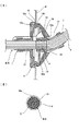
グロメット10はゴムまたはエラストマーで一体成形しており、円錐状に拡径する拡径筒部12の小径側端に第1小径筒部11を連続させて突設していると共に、拡径筒部12の大径側には薄肉の半割れ状の閉鎖部20を設け、該閉鎖部の中央より第2小径筒部21を突設し、拡径筒部12の大径側の外周に車体係止凹部16を環状に設けている。
上記拡径筒部12の外表面には複数の突条部13を放射状に突設すると共に、上記拡径筒部12の内部には上記第1小径筒部11と連続させた小径筒延在部18を設けている
【0014】
上記拡径筒部12内に突出する小径筒延在部18の先端18cは、拡径筒部12の外周に設けている上記車体係止凹部16と略同一位置まで延出している。また、小径筒延在部18と小径筒部11の内径は挿通されるワイヤハーネスW/Hの外径よりも小さく設定することでワイヤハーネスW/Hが密嵌できる構成とし、かつ、小径延在部18の内周面に軸線方向Lに間隔をあけて3つの環状のリブ18aを突設している。
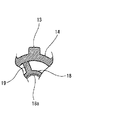
また、図4に示すように、小径筒延在部18の外面18bを先端18cから小径筒部11との連結点である基端に向けて肉厚が大となるように角度θ傾斜させたテーパー形状の傾斜面18bとしている。さらに、図2および図6〜7に示すように、小径筒延在部18の外周面から4つの略台形状のめくれ防止リブ19を等間隔をかけて軸線方向に突設し拡径筒部12の内面に連結している。
拡径筒部12から外方に突出する上記第1小径筒部11の外周面には、2本の環状リブ11aを設けると共に、小径筒部11の先端側の側面に対向して2つのスリット11bを切り欠いている。
【0015】
車体係止凹部16は、図9に示すように、大径端側に突出させた大径側壁16aと、溝16cを挟んで対向させた小径側壁16bとからなる。溝16cは、その奥に前後方向の肉抜部16d、16eを設けると共に溝底面にリップ16fを突出させている。
【0016】
拡径筒部12の外表面に突設する上記突条部13は、周方向に間隔をあけて8本設け、グロメット軸線方向に延在する8本の突条部13を突設し、車体係止凹部16を挟む小径側壁16bの先端から第1小径筒部11との連結端と隙間をあけた近傍位置まで軸線方向に延在させている。
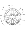
上記突条部13の幅は軸線方向Lで同一としているため、図1に示すように、小径筒部11側から小径側壁16b側にかけて放射状に拡がった状態で延在する。小径筒部11側の突条部13の先端部13aは隣接する突条部13同士を密に配置し、小径側壁16b側の突条部13の端部13cでは隣接する突条部13の間には間隔があき、拡径筒部12の外周面からなる三角形状の窪み部14が小径側から大径側へと広がる方向に発生している。
また、突条部13の先端面は第1小径筒部11の軸線方向と平行となるように傾斜させて形成し、第1小径筒部11の外周面に隙間25をあけてラップさせている。
【0017】
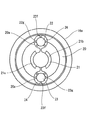
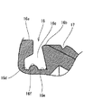
上記突条部13の突出量は、図2に示すように、小径側の先端部13aから車体パネルPの貫通穴Hへの挿通時に貫通穴周縁との接触点13bとなる位置まで漸次減少させ、該接触点13bから小径側壁16bと同じ高さとなる位置13dまでは傾斜角度を小さく変え、該位置13dから終端部13cまではグロメット10の軸線方向Lと略平行な平坦部としていると共に、該位置13dと隣接して小径側壁16b側に切欠部17を断面V字状に凹設している。
【0018】
上記拡径筒部13の大径側端面には薄肉半割れ状として上記閉鎖部20を設け、該閉鎖部20の中央より前記第2小径筒部21の半環状部21c、21bを突出させて、前記第2小径筒部21を設けている。
【0019】
また、グロメット10にはウオッシャー用チューブとフードケーブルを貫通させるための2本のケーブル挿通筒部22、23を一体成形している。
ケーブル挿通筒部22、23は、拡径筒部12の外周面の窪み部14に開口22a、23aを設け、拡径筒部12内を通り、閉鎖部20より突出させている。この突出部22b、23bの突出端は閉鎖部22c、23cとし、ケーブルを通す時に切断部22d、23dで切断して開口としている。また、一方のケーブル挿通部22の内周面には密着用の環状リブ22eを2つ突設していると共に、他方のケーブル挿通部23の内周面には図10に示すように、上記環状リブ22eよりも突出量が大きく、かつ、突出方向が傾斜した環状リブ23eを2つ突設している。
【0020】
また、図5に示すように、閉鎖部20のケーブル挿通筒部22、23の周囲には凹部24を設け、ケーブル挿通部22、23の外周に凹部24の内側面20aと空間をあけた状態で4つのリブ22g、23gを突出していると共に、1つの連結部22f、23fで閉鎖部20aと連結されている。
【0021】
次に、上記構成のグロメット10をワイヤハーネスに取り付ける方法について説明する。
まず、ライン上で電線群の間に止水剤が充填されて線間止水を施されたワイヤハーネスW/Hをグロメット10に貫通させる。
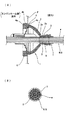
詳しくは、図13(A)(B)に示すように、ワイヤハーネスW/Hを構成する各電線Wの間の隙間に止水剤Sを充填して発泡シート(図示せず)を巻いて止水部Aを設け、該止水部Aが小径筒延在部18に位置するように、ワイヤハーネスW/Hを第1小径筒部11、小径筒延在部18および第2小径筒部21に挿通し、ワイヤハーネスW/Hと各小径筒部11、21とをテープTで巻いて固定する。
この際、第1小径筒部11および小径筒延在部18の内径はワイヤハーネスW/Hの外径よりも小さく設定されているので、広げながら小径筒部11および小径筒延在部18にワイヤハーネスW/Hを通して、該ワイヤハーネスの外周面に密着させている。
これにより、小径筒延在部18での断面は、図13(B)に示すように、小径筒延在部18の環状リブ18aがワイヤハーネスW/Hの外周面に密着し、止水剤Sの充填と合わせて完全な防水対策が為されている。
【0022】
次に、グロメット10の装着作業について説明する。
エンジンルーム側室外(Y)側よりグロメット10の第1小径筒部11を車体パネルPの貫通穴Hを通して室内側(X)に押し込む。
グロメット10の拡径筒部12が貫通穴Hを通り、貫通穴Hの内径と同一となる突条部13の接触点13bに達すると、突条部13と貫通穴H内周面との圧接で節度感を作業者に発生させる。作業者はこの時点から、グロメット10を一気に押し込み、突条部13を押し潰すように貫通穴Hに貫通させる。
この際、突条部13の間の窪み部14があるため、窪み部14が撓んで、拡径筒部12をスムーズに縮径させることができる。かつ、突条部13の傾斜角度も緩やかとしているため、低挿入力で押し込むことができる。
【0023】
さらに、突条部13の外面が、車体係止凹部16の小径側壁16bの先端突出部と同一高さに達すると、貫通穴Hの周縁が切欠部17に嵌り作業者に2回目の節度感を与える。この位置13dから突条部13の外面は軸方向と平行な平坦面となり、貫通穴H内に真っすぐな状態で小径側壁16bの突出端が貫通するようにガイドされるので、2回目の節度感からはただ押し込むだけで貫通穴Hをスムーズに車体係止凹部16に落とし込んで係止させることできる。
【0024】
詳しくは、突条部13の外面を貫通穴Hの内周面で押圧し、拡径筒部12を縮径させながら小径側壁16bの突出端が貫通穴Hを通過し、小径側壁16bが貫通穴Hを通過すると、初期位置に弾性復帰し、小径側壁16bと大径側壁16aの間の溝16c内に貫通穴Hの周縁部が落し込まれ、小径側壁16bと大径側壁16aの対向面が車体パネルPの両面に圧接し、かつ、貫通穴Hの内周面がリップ16fと圧接して、グロメット10は車体パネルPの貫通穴Hにシール状態で係止され、グロメット10を一方向へ移動させるだけのワンモーションで車体パネルの貫通穴に装着することができる。
【0025】
上記構成のグロメット10によると、拡径筒部12内部に突出させた小径筒延在部18にワイヤハーネスW/Hの止水剤Sが硬化した止水部Aを配置しているため、止水部Aが拡径筒部12より車室(X)側に突出した小径筒部11に位置せず、ワイヤハーネスW/Hを小径筒部11と共に容易に屈曲させることが可能となり、ワイヤハーネスW/Hの車室(X)側での配策自由度を向上させることができる。
【0026】
さらに、小径筒延在部18をめくれ防止リブ19で補強しているので、小径筒延在部18がめくれるのが防止でき、小径筒延在部18とワイヤハーネスW/Hとの密着を安定確保することができる。また、めくれ防止リブ19は拡径筒部12にも連結されて補強されているので、車体パネルP取付状態でワイヤハーネスW/Hに引っ張り力が作用しても拡径筒部12の変形を抑制でき、その結果、車体係止凹部が貫通穴Hの周縁から外れるのを防止できる。
【0027】
また、小径筒延在部18の外周面は先端18cから小径筒部11連結側の基端にかけて肉厚が増加する傾斜面18bとしているため、小径筒延在部18の締付力が軸線方向で小径筒部11側の方へいくに従がって増加するので、ワイヤハーネスW/Hの止水部Aの止水剤Sが小径筒部11側に移動してしまうのを防止できる。即ち、ワイヤハーネスW/Hの電線間にシリコン等の止水剤Sを塗布してから20〜30秒程でグロメット10に挿通すると、止水剤Sが十分に硬化してない場合があるが、そのような場合に止水剤Sが小径筒部11に流れるのが防止されて止水部Aが小径筒部11内に配置しないようにできるので、ワイヤハーネスW/Hが小径筒部11と共に容易に屈曲するように確保することが可能となる。
【0028】
また、ワイヤハーネスW/Hが屈曲して配策されるのに伴なって小径筒部11が屈曲しても、小径筒部11と突条部13の先端面13aとの間に隙間25をあけているので、小径筒部11と突条部13が干渉せず、ワイヤハーネスW/Hを小径筒部11と共に容易に屈曲させることができると共に、車体係止凹部16と車体パネルPとの密着箇所に変形が及ぶのを防止できる。
【0029】
また、小径筒延在部18と小径筒部11の内径をワイヤハーネスW/Hの外径よりも小さくしているので、ワイヤハーネスW/Hが小径筒部11と小径筒部延在部18の両方と密着し止水性を向上させることができる。
さらに、小径筒延在部18の内周面に複数の環状のリブ18aを突出させているので、リブ18aでワイヤハーネスW/Hと強く密着させることができ、止水性をより向上させることができる。
【0030】
また、拡径筒部12の外周面に突条部13を突設することで、挿入抵抗が低減でき、挿入作業性を高めることができる。かつ、突条部13の小径側先端を第1小径筒部11の外周面にオーバラップさせているため、ワイヤハーネスが室外側に引っ張られると突条部13の端面が第1小径筒部11の外周面に圧着してワイヤハーネスの移動を阻止し、グロメット10を貫通穴から外れることを確実に阻止する。
【0031】
【発明の効果】
以上の説明より明らかなように、本発明のグロメットによれば、拡径筒部の内部に突出させた小径筒延在部をワイヤハーネスの線間止水された止水部を配置することとしているので、止水部が拡径筒部より突出した小径筒部に位置せず、ワイヤハーネスを小径筒部と共に容易に屈曲させることが可能となり、配策自由度を向上させることができる。
また、上記小径筒延在部の外面と上記拡径筒部の内面との間に複数のめくれ防止リブを間隔をあけて連結しているので、小径筒延在部がめくれるのが防止でき小径筒延在部とワイヤハーネスとの密着を確保することができると共に、拡径筒部の外周面の車体係止凹部の変形も防止され、グロメットの車体パネル保持力も向上させることができる。
【図面の簡単な説明】
【図1】本発明の施形態のグロメットの右側面図である。
【図2】図1のII−II線断面図である。
【図3】図1のIII−III線断面図である。
【図4】小径筒延在部の拡大断面図である。
【図5】上記グロメットの左側面図である。
【図6】図2のIV−IV線断面図である。
【図7】要部拡大断面図である。
【図8】要部拡大断面図である。
【図9】車体係止凹部の要部拡大断面図である。
【図10】ケーブル挿通筒部の要部拡大断面図である。
【図11】グロメットの斜視図である。
【図12】グロメットの斜視図である。
【図13】(A)はグロメットの車体取付状態を示す断面図、(B)は小径筒延在部の断面図である。
【図14】(A)(B)は従来のグロメットを示す図面である。
【符号の説明】
10 グロメット
11 第1小径筒部(小径筒部)
12 拡径筒部
13 突条部
13a 先端面
14 窪み部
16 車体係止凹部
18 小径筒延在部
18b 傾斜面
19 めくれ防止リブ[0001]
TECHNICAL FIELD OF THE INVENTION
The present invention relates to a grommet, and more particularly, to a one-motion grommet that is assembled to a wire harness to be routed to an automobile and is mounted by being pushed into a through hole of a vehicle body panel from one direction, wherein It is intended to protect, waterproof and dustproof.
[0002]
[Prior art]
Conventionally, a grommet is attached to a wire harness that is routed from the engine room of an automobile to the vehicle interior, and a grommet is attached to a through hole of a vehicle body panel that separates the engine room and the vehicle compartment, and a wire harness that passes through the through hole is provided. The protection, waterproofness, dustproofing and sound insulation from the engine compartment side to the vehicle compartment are achieved.
[0003]
As the grommet of this type, the present applicant has previously provided a large number of grommets including a grommet as shown in FIGS. 14A and 14B in Japanese Patent Application Laid-Open No. 2002-171645.
The grommet 1 shown in FIG. 14 includes a large-diameter cylinder portion 2 and a small-diameter cylinder portion 3 that is continuous with the small-diameter side of the large-diameter cylinder portion 2. The large-diameter side is a
[0004]
For mounting the vehicle body panel P into the through hole H, the small-diameter cylindrical portion 3 of the grommet 1 was inserted into the through hole H from the outside on the engine room side, and the enlarged cylindrical portion 2 contacted the inner peripheral surface of the through hole H. From the point in time, the diametrically enlarged cylindrical portion 2 is deformed so as to be squashed inward by passing it through the through hole, and the
[0005]
[Patent Document 1]
JP-A-2002-171645 [0006]
[Problems to be solved by the invention]
The one-motion grommet 1 shown in FIG. 14 has the advantage that the workability of mounting the vehicle body panel into the through hole is good and the holding force after the grommet 1 is attached to the through hole is high. There is room for improvement in the case where the
In other words, when the inter-line water blocking portion A is provided, the inter-line water blocking portion A is closely fitted with the small-diameter cylindrical portion 3 being pushed and spread. The small-diameter cylindrical portion 2 cannot be easily bent because it is filled and hardened. Therefore, when it is necessary to wire and arrange the wire harness W / H on the indoor side, when the wire harness drawn out from the small-diameter tube portion 2 is bent, the space of the small-diameter tube portion 3 is wasted, and the wire harness W / H is wasted. There is a problem that space must be secured.
[0007]
The present invention has been made in view of the above-described problem, and has an object to improve a grommet attached to a wire harness provided with a water stop portion between lines in advance to increase flexibility of a wire harness pulled out from the grommet. .
[0008]
[Means for Solving the Problems]
In order to solve the above-described problems, the present invention includes an enlarged-diameter cylinder portion, and a small-diameter cylinder portion that is continuous on the small-diameter side of the enlarged-diameter cylinder portion, and an automobile wire harness is provided on the enlarged-diameter cylinder portion and the small-diameter cylinder portion. A grommet that is inserted into the through-hole of the vehicle body from the small-diameter tube portion side in a state where the small-diameter tube portion is mounted to penetrate, and locks a vehicle-body locking concave portion provided on an outer peripheral surface of the large-diameter tube portion to a vehicle body panel,
A large-diameter side wall on the large-diameter end side of the large-diameter cylindrical portion with the vehicle-body locking recess interposed therebetween; and a small-diameter side wall on a small-diameter side opposed to the large-diameter side wall. Through the hole,
A plurality of projecting ridges extending in the axial direction are provided on the outer peripheral surface of the enlarged-diameter tube portion, and a small-diameter tube extension portion projecting into the enlarged-diameter tube portion is provided on the small-diameter tube portion. The small-diameter tube extension portion is provided as a water-stop portion, and a plurality of turning-up preventing ribs are protruded from the outer surface of the small-diameter tube extension portion at intervals and connected to the inner surface of the large-diameter cylinder portion,
Provided is a grommet, wherein the continuous diameter of the small-diameter cylinder extending portion and the small-diameter cylinder portion is set to be smaller than the outer diameter of the wire harness so that the wire harness is closely fitted and penetrated. I have.
[0009]
With the above configuration, the small-diameter tube portion is provided with a small-diameter tube extension portion protruding inside the enlarged-diameter tube portion, and the small-diameter tube extension portion is located at a position where the water stopping portion of the wire harness is arranged. The water stop portion is not located at the small-diameter tube portion protruding from the large-diameter tube portion, so that the wire harness can be easily bent together with the small-diameter tube portion, and the degree of freedom in arrangement can be improved.
Further, when the small-diameter tube extending portion is reinforced by the turning-up preventing rib, the small-diameter tube extending portion can be prevented from being turned up, and the close contact between the small-diameter tube extending portion and the wire harness can be secured stably. In addition, since the turning-up prevention rib is also connected to and reinforced with the enlarged-diameter tube portion, the enlarged-diameter tube portion is hardly deformed, so that the deformation of the vehicle body locking recess on the outer peripheral surface is also prevented, and the grommet body panel is provided. Can also be improved.
[0010]
Also, since the inside diameter of the small-diameter tube extension and the small-diameter tube is smaller than the outer diameter of the wire harness, the outer surface of the wire harness is in close contact with both the small-diameter tube and the small-diameter tube extension. Can be lengthened, so that the water stopping performance can be improved.
Further, by projecting the ridge on the outer peripheral surface of the enlarged diameter cylindrical portion, the mounting force of the vehicle body panel in the through hole can be reduced, and the holding force after the body panel is mounted in the through hole can be increased.
[0011]
In addition, the small-diameter cylindrical extension portion penetrates the water-stop portion of the wire harness, which is filled in advance with a line-stopping agent, in a tightly fitted state, while the small-diameter cylindrical portion has a water-stop portion of the wire harness. It does not penetrate.
[0012]
With the above configuration, the waterproofing agent is filled between the wire groups of the wire harness before the wire is inserted into the grommet, so that the filling operation of the waterproofing agent can be performed on the wire harness assembly line, and the workability is improved. Can be increased.
After the wire harness is inserted through the grommet, for example, a waterproofing agent injection needle may be inserted between the electric wire groups of the wire harness located in the small-diameter cylindrical extension portion to fill the waterproofing agent.
[0013]
BEST MODE FOR CARRYING OUT THE INVENTION
Hereinafter, embodiments of the present invention will be described with reference to the drawings.
The
A plurality of
The
Further, as shown in FIG. 4, the
Two
[0015]
As shown in FIG. 9, the vehicle
[0016]
Eight protruding
Since the width of the
Further, the distal end surface of the protruding
[0017]
As shown in FIG. 2, the amount of protrusion of the
[0018]
The closing
[0019]
Further, the
The cable
[0020]
Further, as shown in FIG. 5, a
[0021]
Next, a method of attaching the
First, the wire harness W / H, which is filled with a water-stopping agent between the electric wire groups on the line and water-stopped between the lines is passed through the
Specifically, as shown in FIGS. 13A and 13B, a gap between the electric wires W constituting the wire harness W / H is filled with a water-stopping agent S, and a foam sheet (not shown) is wound thereon. A water stop portion A is provided, and the wire harness W / H is connected to the first small-
At this time, since the inner diameters of the first small-
As a result, as shown in FIG. 13B, the cross section of the small-diameter
[0022]
Next, the mounting operation of the
The first small-diameter
When the enlarged
At this time, since there is the
[0023]
Further, when the outer surface of the
[0024]
Specifically, the outer surface of the
[0025]
According to the
[0026]
Further, since the small-diameter
[0027]
Further, since the outer peripheral surface of the small-diameter
[0028]
Further, even if the small-diameter
[0029]
Further, since the inner diameters of the small-diameter
Further, since a plurality of
[0030]
Further, by projecting the
[0031]
【The invention's effect】
As is clear from the above description, according to the grommet of the present invention, the small-diameter cylindrical extension protruding inside the large-diameter cylindrical portion is provided with the water-stop portion between the wires of the wire harness. Therefore, the water stopping portion is not located at the small-diameter tube portion protruding from the large-diameter tube portion, and the wire harness can be easily bent together with the small-diameter tube portion, so that the degree of freedom in arrangement can be improved.
Further, since a plurality of turning-up preventing ribs are connected with an interval between the outer surface of the small-diameter tube extending portion and the inner surface of the large-diameter tube portion, the small-diameter tube extending portion can be prevented from being turned up and small diameter. The close contact between the tube extending portion and the wire harness can be ensured, the deformation of the vehicle body locking concave portion on the outer peripheral surface of the enlarged diameter tube portion can be prevented, and the holding force of the grommet on the vehicle body panel can be improved.
[Brief description of the drawings]
FIG. 1 is a right side view of a grommet according to an embodiment of the present invention.
FIG. 2 is a sectional view taken along line II-II of FIG.
FIG. 3 is a sectional view taken along line III-III of FIG. 1;
FIG. 4 is an enlarged sectional view of a small-diameter cylinder extending portion.
FIG. 5 is a left side view of the grommet.
FIG. 6 is a sectional view taken along line IV-IV of FIG. 2;
FIG. 7 is an enlarged sectional view of a main part.
FIG. 8 is an enlarged sectional view of a main part.
FIG. 9 is an enlarged sectional view of a main part of a vehicle body locking recess.
FIG. 10 is an enlarged sectional view of a main part of a cable insertion tube portion.
FIG. 11 is a perspective view of a grommet.
FIG. 12 is a perspective view of a grommet.
13A is a cross-sectional view showing a grommet mounted state on a vehicle body, and FIG. 13B is a cross-sectional view of a small-diameter cylinder extending portion.
14A and 14B are views showing a conventional grommet.
[Explanation of symbols]
10
12 Large-diameter
Claims (2)
上記車体係止凹部を挟んで拡径筒部の大径端側の大径側壁と、該大径側壁と対向する小径側の小径側壁を備え、小径側壁を内方に撓ませて、上記貫通穴を通過させるようにしており、
上記拡径筒部の外周面には、軸線方向に延在する複数の突条部を突設し、かつ、 上記小径筒部に上記拡径筒部内部に突出させた小径筒延在部を設け、該小径筒延在部を止水部とすると共に、上記小径筒延在部の外面より複数のめくれ防止リブを間隔をあけて突設して上記拡径筒部の内面に連結し、
該小径筒延在部と上記小径筒部の連続する内径は上記ワイヤハーネスの外径よりも小さく設定してワイヤハーネスを密嵌させて貫通させる構成としていることを特徴とするグロメット。The small-diameter cylinder includes an enlarged-diameter cylinder portion, and a small-diameter cylinder portion that is continuous with the small-diameter side of the enlarged-diameter cylinder portion. A grommet that is inserted into the through hole of the vehicle body from the side of the vehicle body and locks the vehicle body locking recess provided on the outer peripheral surface of the enlarged-diameter cylindrical portion to the vehicle body panel,
A large-diameter side wall on the large-diameter end side of the large-diameter cylindrical portion with the vehicle-body locking recess interposed therebetween; and a small-diameter side wall on a small-diameter side opposed to the large-diameter side wall. Through the hole,
A plurality of projecting ridges extending in the axial direction are provided on the outer peripheral surface of the enlarged-diameter tube portion, and a small-diameter tube extension portion projecting into the enlarged-diameter tube portion is provided on the small-diameter tube portion. The small-diameter tube extension portion is provided as a water-stop portion, and a plurality of turning-up preventing ribs are protruded from the outer surface of the small-diameter tube extension portion at intervals and connected to the inner surface of the large-diameter cylinder portion,
A grommet characterized in that a continuous inner diameter of the small-diameter tube extending portion and the small-diameter tube portion is set smaller than an outer diameter of the wire harness so that the wire harness is closely fitted and penetrated.
Priority Applications (5)
| Application Number | Priority Date | Filing Date | Title |
|---|---|---|---|
| JP2002348857A JP4029722B2 (en) | 2002-11-29 | 2002-11-29 | Grommet |
| US10/721,356 US6897380B2 (en) | 2002-11-29 | 2003-11-26 | Grommet for a wire harness |
| DE60303658T DE60303658T2 (en) | 2002-11-29 | 2003-11-27 | Cuff for a wiring harness |
| EP03292954A EP1424245B1 (en) | 2002-11-29 | 2003-11-27 | Grommet for a wire harness |
| CN200310118845.2A CN1273333C (en) | 2002-11-29 | 2003-11-28 | Protective ring for bunch |
Applications Claiming Priority (1)
| Application Number | Priority Date | Filing Date | Title |
|---|---|---|---|
| JP2002348857A JP4029722B2 (en) | 2002-11-29 | 2002-11-29 | Grommet |
Publications (2)
| Publication Number | Publication Date |
|---|---|
| JP2004187357A true JP2004187357A (en) | 2004-07-02 |
| JP4029722B2 JP4029722B2 (en) | 2008-01-09 |
Family
ID=32751652
Family Applications (1)
| Application Number | Title | Priority Date | Filing Date |
|---|---|---|---|
| JP2002348857A Expired - Lifetime JP4029722B2 (en) | 2002-11-29 | 2002-11-29 | Grommet |
Country Status (1)
| Country | Link |
|---|---|
| JP (1) | JP4029722B2 (en) |
Cited By (8)
| Publication number | Priority date | Publication date | Assignee | Title |
|---|---|---|---|---|
| JP2008027692A (en) * | 2006-07-20 | 2008-02-07 | Sumitomo Wiring Syst Ltd | Grommet and molding method of the grommet |
| JP2008307945A (en) * | 2007-06-12 | 2008-12-25 | Sumitomo Wiring Syst Ltd | Grommet |
| JP2013150509A (en) * | 2012-01-23 | 2013-08-01 | Yazaki Corp | Attachment structure of grommet |
| JP2015015869A (en) * | 2013-07-08 | 2015-01-22 | 住友電装株式会社 | Grommet |
| JP2017010649A (en) * | 2015-06-17 | 2017-01-12 | 矢崎総業株式会社 | Grommet and wire harness having the same |
| JP2018002066A (en) * | 2016-07-07 | 2018-01-11 | 鬼怒川ゴム工業株式会社 | Grommet structure of steering shaft |
| CN112636284A (en) * | 2019-10-07 | 2021-04-09 | 矢崎总业株式会社 | Grommet and wire harness |
| CN114498473A (en) * | 2020-10-28 | 2022-05-13 | 住友电装株式会社 | Wire sheath |
-
2002
- 2002-11-29 JP JP2002348857A patent/JP4029722B2/en not_active Expired - Lifetime
Cited By (10)
| Publication number | Priority date | Publication date | Assignee | Title |
|---|---|---|---|---|
| JP2008027692A (en) * | 2006-07-20 | 2008-02-07 | Sumitomo Wiring Syst Ltd | Grommet and molding method of the grommet |
| US7683265B2 (en) | 2006-07-20 | 2010-03-23 | Sumitomo Wiring Systems, Ltd. | Grommet and forming method for the grommet |
| JP2008307945A (en) * | 2007-06-12 | 2008-12-25 | Sumitomo Wiring Syst Ltd | Grommet |
| JP2013150509A (en) * | 2012-01-23 | 2013-08-01 | Yazaki Corp | Attachment structure of grommet |
| JP2015015869A (en) * | 2013-07-08 | 2015-01-22 | 住友電装株式会社 | Grommet |
| JP2017010649A (en) * | 2015-06-17 | 2017-01-12 | 矢崎総業株式会社 | Grommet and wire harness having the same |
| JP2018002066A (en) * | 2016-07-07 | 2018-01-11 | 鬼怒川ゴム工業株式会社 | Grommet structure of steering shaft |
| CN112636284A (en) * | 2019-10-07 | 2021-04-09 | 矢崎总业株式会社 | Grommet and wire harness |
| CN112636284B (en) * | 2019-10-07 | 2023-08-22 | 矢崎总业株式会社 | Grommet and wire harness |
| CN114498473A (en) * | 2020-10-28 | 2022-05-13 | 住友电装株式会社 | Wire sheath |
Also Published As
| Publication number | Publication date |
|---|---|
| JP4029722B2 (en) | 2008-01-09 |
Similar Documents
| Publication | Publication Date | Title |
|---|---|---|
| EP1424245B1 (en) | Grommet for a wire harness | |
| JP3283180B2 (en) | Grommet | |
| JPH1047548A (en) | Grommet and manufacture thereof | |
| JP2010154601A (en) | Grommet | |
| CN113285407B (en) | Grommet and wire harness | |
| CN112636284A (en) | Grommet and wire harness | |
| JP2004187357A (en) | Grommet | |
| JP4483767B2 (en) | Grommet | |
| JP3637851B2 (en) | Grommet with auxiliary equipment | |
| JP4026486B2 (en) | Grommet | |
| JP2003009361A (en) | Watertight structure based on grommet | |
| JP3985670B2 (en) | Grommet | |
| JP2004187354A (en) | Grommet | |
| JP2004187356A (en) | Grommet | |
| JPH09289725A (en) | Grommet | |
| JP2005065354A (en) | Structure for fixing grommet to wire harness | |
| JP3296161B2 (en) | Grommet | |
| JP3480424B2 (en) | Grommet | |
| JP2767731B2 (en) | Grommet waterproof structure | |
| JP3085189B2 (en) | Grommet | |
| JP3309805B2 (en) | Grommet | |
| JP3090035B2 (en) | Grommet | |
| JP3085190B2 (en) | Grommet | |
| JP3000127B2 (en) | Grommet and mounting method | |
| JP7463984B2 (en) | Grommet Assembly and Wire Harness |
Legal Events
| Date | Code | Title | Description |
|---|---|---|---|
| A621 | Written request for application examination |
Free format text: JAPANESE INTERMEDIATE CODE: A621 Effective date: 20041222 |
|
| A977 | Report on retrieval |
Free format text: JAPANESE INTERMEDIATE CODE: A971007 Effective date: 20061218 |
|
| A131 | Notification of reasons for refusal |
Free format text: JAPANESE INTERMEDIATE CODE: A131 Effective date: 20070116 |
|
| A521 | Request for written amendment filed |
Free format text: JAPANESE INTERMEDIATE CODE: A523 Effective date: 20070315 |
|
| TRDD | Decision of grant or rejection written | ||
| A01 | Written decision to grant a patent or to grant a registration (utility model) |
Free format text: JAPANESE INTERMEDIATE CODE: A01 Effective date: 20070925 |
|
| A61 | First payment of annual fees (during grant procedure) |
Free format text: JAPANESE INTERMEDIATE CODE: A61 Effective date: 20071008 |
|
| R150 | Certificate of patent or registration of utility model |
Ref document number: 4029722 Country of ref document: JP Free format text: JAPANESE INTERMEDIATE CODE: R150 Free format text: JAPANESE INTERMEDIATE CODE: R150 |
|
| FPAY | Renewal fee payment (event date is renewal date of database) |
Free format text: PAYMENT UNTIL: 20101026 Year of fee payment: 3 |
|
| FPAY | Renewal fee payment (event date is renewal date of database) |
Free format text: PAYMENT UNTIL: 20111026 Year of fee payment: 4 |
|
| FPAY | Renewal fee payment (event date is renewal date of database) |
Free format text: PAYMENT UNTIL: 20121026 Year of fee payment: 5 |
|
| FPAY | Renewal fee payment (event date is renewal date of database) |
Free format text: PAYMENT UNTIL: 20131026 Year of fee payment: 6 |
|
| EXPY | Cancellation because of completion of term |