【0001】
【発明の属する技術分野】
本発明は、グラビア製版方法に関し、さらに詳しくは面積階調および深度階調性を有するグラビア版を簡便な方法で製版する方法に関する。
【0002】
【従来の技術】
従来、グラビア刷版は、図3に示すように、銅製基材(実際はシリンダー形状)1の表面に感光層2を形成し、色分解したマスクを介して露光および現像し、レジスト層3を形成し、エッチングおよびレジスト層を剥離し、画像状に凹部を形成し、全面を耐久性の目的でクロムメッキを施すことにより製造されている。そして、上記凹部にインキを保持させて、紙やフィルム表面に該インキを転写して印刷を行っている。この際、原稿画像の階調性の再現には、上記凹部の面積を調整して行っているが、このような版によって再現される画像は所謂ボリウム感に欠け、滑らかな印刷画像ではなかった。
【0003】
【発明が解決しようとする課題】
上記の欠点を解決する方法としては、凹部の面積とともに、凹部の深さを変化させる所謂深度階調方法が行われているが、これらの方法としては、例えば、エッチングする前のレジスト層の形成を(1)連続調原版フィルムを使用する方法、(2)網点階調ポジを使用する方法、(3)レジスト層を使用せずに、物理的に基材を彫刻する方法、などが挙げられる。しかしながら、これらの従来方法は、その製版工程が複雑でコスト高であるとともに、深度階調設計の自由度(面積階調と独立して深度階調を設計できる度合い)と製版の安定性に欠けるものであった。
従って本発明の目的は、工程が簡略であり、かつ深度階調設計の自由度が大きく、製版の安定性にも優れたグラビア製版方法を提供することにある。
【0004】
【課題を解決するための手段】
上記目的は以下の本発明によって達成される。すなわち、本発明は、グラビア刷版用基材の表面に、該基材用のエッチング液を部分的に透過する第一の感光層を形成する工程、該感光層に光量および露光範囲を制御して画像状に露光した後、現像して画像状の第一のレジスト層を形成する工程、該第一のレジスト層の全面に第二の感光層を形成する工程、該第二の感光層を第一のレジスト層と整合させて露光および現像して第二のレジスト層を形成する工程、基材をエッチングする工程、および第一および第二のレジスト層を除去する工程からなることを特徴とする面積および深度階調性を有するグラビア製版方法を提供する。
【0005】
また、本発明は、グラビア刷版用基材の表面に、該基材用のエッチング液を部分的に透過する第一の感光層を形成する工程、該第一の感光層の表面に第二の感光層を形成する工程、該第二の感光層を画像状に露光および現像して第二のレジスト層を形成する工程、前記第一の感光層を上記第二のレジスト層に整合させ、かつ光量を制御して画像状に露光した後、現像して画像状の第一のレジスト層を形成する工程、基材をエッチングする工程、および第一および第二のレジスト層を除去する工程からなることを特徴とする面積および深度階調性を有するグラビア製版方法を提供する。
【0006】
【発明の実施の形態】
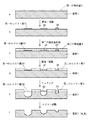
次に図面に示す好ましい実施の形態を挙げて本発明をさらに詳しく説明する。図1は、第一の本発明の製版方法を図解的に説明する図である。第一発明では、先ず、グラビア刷版用基材1の表面に、該基材用のエッチング液を部分的に透過する第一の感光層2を形成する。
【0007】
ここで使用する基材1は従来公知の基材であり、1例としては長さ500〜2,100mm、直径150〜500mmの銅製シリンダーである。また、第一の感光層は、その厚みまたは架橋密度によって上記基材のエッチング液をある程度の速度で透過できる感光層である。このような感光層を形成できる感光剤(レジスト液)としては、例えば、重クロム酸含有のゼラチンなどが挙げられる。また、このような感光層2は、例えば、リングコート、ロールコートおよびシート状に加工し転写するなどの方法により、数十μmの厚さに形成することが好ましい。
【0008】
次に上記感光層2を光量および露光範囲を制御して画像状に露光した後、現像して画像状の第一のレジスト層31〜33を形成する。上記露光は、光量および露光面積が自由に変えられる光源、例えば、レーザー光線を用いることが好ましい。該レーザー光露光装置としては、例えば、フィルムセッター等に用いられるYAGレーザー装置などが挙げられる。
【0009】
図1aに示す第一の感光層2にレーザー光をその強度および露光面積を変えて露光および現像することによって、図1bに示されるように、レーザー光の強度および面積に応じた厚みまたは密度のレジスト層31〜33が形成される。31が最も少ない光量を受け、33が最も多い光量を受けた部分であり、32がその中間である。なお、不図示であるが、最も低い光量を受けた領域にはレジスト層がなくてもよい。なお、現像は従来公知の方法でよい。
【0010】
上記において使用する第一の感光層2は、光硬化性であることが好ましい。すなわち、照射光量が少ない領域は感光層2の硬化の程度が低く、現像によって薄い(または密度の低い)レジスト層31となり、一方、照射光量が多い領域は現像によって厚い(または密度の高い)層33となる。このように第一のレジスト層31〜33をその厚みまたは密度を変えることによって、該レジスト層31〜33のエッチング液に対する透過性を変えることができる。
【0011】
次に図1cに示すように上記第一のレジスト層31〜33の全面に第二の感光層4を形成する。この感光層4は第一のレジスト層31〜33に整合させて露光および現像することにより、図1dに示すように第二のレジスト層5が形成される。上記第二の感光層4を形成する感光剤が光分解型であると、露光に際し、前記の第一のレジスト層31〜33をさらに硬化させ、レジスト層31〜33の物性(エッチング液透過性)を変化させるので、光硬化型の感光剤であることが好ましい。
【0012】
このような光分解化型の感光剤としては、例えば、重クロム酸含有のゼラチンなどが挙げられる。また、このような感光層4は、例えば、ロールコート、リングコートおよびシート状に加工し転写するなどの方法により数十μmの厚さに形成することが好ましい。第二の感光層の光照射は、光量を変更して行う必要はないので、通常のフラッシュ露光でもよい。勿論、レーザー光による均一露光でもよい。現像は従来公知の方法でよい。
【0013】
図1eに示すように第一のレジスト層31〜33および第二のレジスト層5を形成した後にエッチング処理を行う。このエッチング処理によって第二のレジスト層5が存在する領域では基材1は全くエッチングされず、第一のレジスト層のうち、31の部分は最もエッチング液が通過し易いので、より深くエッチングされ、33の部分はエッチング液は透過するが、最も透過しにくいので、基板1のエッチング深度は浅くなる。32の部分はその中間である。
【0014】
次に第一および第二のレジスト層を除去することによって、図1fに示すように、エッチング面積およびエッチング深度の異なる凹部が自在に形成され、さらに全面をクロムメッキして面積階調および深度階調に優れたグラビア刷版が得られる。このようなグラビア刷版で印刷することにより、紙などに転写されるインキは面積の大小に加えて、転写されるインキの厚みが異なることから、得られる印刷画像は、視覚的にボリウム感があり、滑らかな印刷画像となる。
【0015】
次に第二の本発明を図2を参照して説明する。第二の発明では、図3aに示すようにグラビア刷版用基材1の表面に、該基材用のエッチング液を部分的に透過する第一の感光層2、および第二の感光層3を形成する。
【0016】
ここで使用する基材、第一の感光層、第二の感光層、露光、現像などは前記第一の発明と大部分が同様であり、異なる部分のみ説明する。第二の発明では、原稿の色分解情報に従って第二の感光層3を前記第一の発明と同様に露光および現像して第二のレジスト層4を形成して図2bの状態とする。次いで第一の発明と同様にして第一の感光層2にレーザー光を第二のレジスト層4に整合させて光量を変化させて露光する。この露光も前記第一の発明の場合と同様である。このようにして図2cに示すように、エッチング液の透過速度が異なる第一のレジスト層31〜33が形成される。以下前記第一の発明と同様にエッチング(図2d)およびレジスト剥離(図2e)などを行う。
【0017】
以上のようにして図2eに示すように、エッチング面積およびエッチング深度の異なる凹部が自在に形成され、面積階調および深度階調に優れたグラビア刷版が得られる。このようなグラビア刷版で印刷することにより、紙などに転写されるインキは面積の大小に加えて、転写されるインキの厚みが異なることから、得られる印刷画像は、視覚的にボリウム感があり、滑らかな印刷画像となる。
【0018】
【発明の効果】
以上の如き本発明によれば、工程が簡略であり、かつ深度階調設計の自由度が大きく、製版の安定性に優れたグラビア製版方法を提供することができる。
【図面の簡単な説明】
【図1】本発明の方法を説明する図。
【図2】本発明の方法を説明する図。
【図3】従来の方法を説明する図。[0001]
TECHNICAL FIELD OF THE INVENTION
The present invention relates to a gravure printing method, and more particularly, to a method for making a gravure printing plate having an area gradation and a depth gradation by a simple method.
[0002]
[Prior art]
Conventionally, as shown in FIG. 3, a gravure printing plate forms a photosensitive layer 2 on the surface of a copper base material (actually a cylinder shape) 1 and exposes and develops through a color-separated mask to form a resist layer 3 Then, the etching and the resist layer are peeled off, a concave portion is formed in an image shape, and the entire surface is plated with chromium for the purpose of durability. Then, the ink is held in the recesses, and the ink is transferred to the surface of paper or a film to perform printing. At this time, the gradation of the original image is reproduced by adjusting the area of the concave portion, but the image reproduced by such a plate lacks a so-called volume feeling and is not a smooth printed image. .
[0003]
[Problems to be solved by the invention]
As a method for solving the above-mentioned drawbacks, a so-called depth gradation method of changing the depth of the concave portion together with the area of the concave portion has been performed. As these methods, for example, formation of a resist layer before etching is performed. (1) a method using a continuous tone master film, (2) a method using halftone gradation positive, (3) a method of physically engraving a substrate without using a resist layer, and the like. Can be However, these conventional methods have complicated plate making processes and high costs, and lack the degree of freedom of depth gradation design (the degree to which depth gradation can be designed independently of area gradation) and the stability of plate making. Was something.
SUMMARY OF THE INVENTION Accordingly, an object of the present invention is to provide a gravure plate making method in which the steps are simple, the degree of freedom of depth gradation design is large, and the plate making stability is excellent.
[0004]
[Means for Solving the Problems]
The above object is achieved by the present invention described below. That is, the present invention provides a step of forming a first photosensitive layer that partially transmits an etching solution for the gravure printing plate on the surface of the gravure printing plate substrate, by controlling the amount of light and the exposure range of the photosensitive layer. After imagewise exposing, developing and forming an image-like first resist layer, forming a second photosensitive layer over the entire surface of the first resist layer, Forming a second resist layer by exposure and development in alignment with the first resist layer, a step of etching the substrate, and a step of removing the first and second resist layers, To provide a gravure plate-making method having an area and depth gradation.
[0005]
Further, the present invention provides a step of forming a first photosensitive layer partially transmitting an etching solution for the substrate on the surface of the substrate for gravure printing plate, and forming a second photosensitive layer on the surface of the first photosensitive layer. The step of forming a photosensitive layer, the step of imagewise exposing and developing the second photosensitive layer to form a second resist layer, aligning the first photosensitive layer with the second resist layer, After controlling the amount of light and exposing in an image form, from the step of developing and forming an image-like first resist layer, the step of etching the base material, and the step of removing the first and second resist layers Provided is a gravure plate making method having area and depth gradation characteristics.
[0006]
BEST MODE FOR CARRYING OUT THE INVENTION
Next, the present invention will be described in more detail with reference to preferred embodiments shown in the drawings. FIG. 1 is a diagram schematically illustrating the plate making method of the first invention. In the first invention, first, a first photosensitive layer 2 that partially transmits an etchant for the gravure printing plate is formed on the surface of the gravure printing plate substrate 1.
[0007]
The substrate 1 used here is a conventionally known substrate, and is, for example, a copper cylinder having a length of 500 to 2,100 mm and a diameter of 150 to 500 mm. Further, the first photosensitive layer is a photosensitive layer that can transmit the etching solution of the base material at a certain speed depending on its thickness or crosslink density. Examples of a photosensitive agent (resist solution) capable of forming such a photosensitive layer include gelatin containing dichromic acid. Further, such a photosensitive layer 2 is preferably formed to have a thickness of several tens of μm by a method such as ring coating, roll coating, and processing into a sheet and transferring.
[0008]
Next, the photosensitive layer 2 is exposed imagewise by controlling the light amount and the exposure range, and then developed to form imagewise first resist layers 31 to 33. For the exposure, it is preferable to use a light source whose light amount and exposure area can be freely changed, for example, a laser beam. Examples of the laser light exposure device include a YAG laser device used for a film setter and the like.
[0009]
By exposing and developing a laser beam on the first photosensitive layer 2 shown in FIG. 1a while changing its intensity and exposure area, as shown in FIG. 1b, a thickness or density corresponding to the intensity and area of the laser beam is obtained. Resist layers 31 to 33 are formed. 31 is the portion receiving the least light amount, 33 is the portion receiving the most light amount, and 32 is the middle. Although not shown, a resist layer may not be provided in a region receiving the lowest light amount. The development may be performed by a conventionally known method.
[0010]
The first photosensitive layer 2 used in the above is preferably photocurable. That is, the region where the irradiation light amount is small has a low degree of curing of the photosensitive layer 2 and becomes a thin (or low density) resist layer 31 by development, while the region where the irradiation light amount is large is a thick (or high density) layer by development. 33. By changing the thickness or density of the first resist layers 31 to 33 as described above, the transmittance of the first resist layers 31 to 33 to the etchant can be changed.
[0011]
Next, as shown in FIG. 1C, a second photosensitive layer 4 is formed on the entire surface of the first resist layers 31 to 33. The photosensitive layer 4 is exposed to light and developed in alignment with the first resist layers 31 to 33 to form the second resist layer 5 as shown in FIG. 1D. If the photosensitive agent forming the second photosensitive layer 4 is of a photodecomposable type, the first resist layers 31 to 33 are further cured during exposure, and the physical properties of the resist layers 31 to 33 (etchant permeability). ) Is changed, so that a photocurable photosensitive agent is preferable.
[0012]
Examples of such a photodecomposable photosensitive agent include gelatin containing dichromic acid. Further, such a photosensitive layer 4 is preferably formed to a thickness of several tens of μm by, for example, a method such as roll coating, ring coating and processing into a sheet and transferring. The light irradiation of the second photosensitive layer does not need to be performed by changing the amount of light, so that ordinary flash exposure may be used. Of course, uniform exposure by laser light may be used. The development may be performed by a conventionally known method.
[0013]
After forming the first resist layers 31 to 33 and the second resist layer 5 as shown in FIG. 1e, an etching process is performed. By this etching process, the substrate 1 is not etched at all in the region where the second resist layer 5 is present, and the portion 31 of the first resist layer is more deeply etched because the etching solution passes most easily, The portion 33 transmits the etchant, but hardly transmits the etchant, so that the etching depth of the substrate 1 is small. The portion 32 is intermediate.
[0014]
Next, by removing the first and second resist layers, concave portions having different etching areas and etching depths are freely formed as shown in FIG. 1f. A gravure printing plate with excellent tone can be obtained. By printing with such a gravure printing plate, the ink transferred to paper or the like has a large or small area and a different thickness of the transferred ink, so that the resulting printed image has a visually sense of volume. There is a smooth printed image.
[0015]
Next, a second invention will be described with reference to FIG. In the second invention, as shown in FIG. 3A, a first photosensitive layer 2 and a second photosensitive layer 3 that partially transmit an etching solution for the gravure printing plate are provided on the surface of the gravure printing plate substrate 1. To form
[0016]
The base material, the first photosensitive layer, the second photosensitive layer, the exposure, the development, and the like used here are almost the same as those of the first invention, and only different parts will be described. In the second invention, the second photosensitive layer 3 is exposed and developed according to the color separation information of the original in the same manner as in the first invention to form the second resist layer 4, and the state shown in FIG. 2B is obtained. Next, in the same manner as in the first invention, the first photosensitive layer 2 is exposed to a laser beam while being adjusted to the second resist layer 4 while changing the amount of light. This exposure is the same as in the first invention. In this way, as shown in FIG. 2C, first resist layers 31 to 33 having different etching liquid transmission speeds are formed. Thereafter, etching (FIG. 2D) and resist peeling (FIG. 2E) are performed in the same manner as in the first invention.
[0017]
As described above, as shown in FIG. 2E, concave portions having different etching areas and etching depths are freely formed, and a gravure printing plate excellent in area gradation and depth gradation is obtained. By printing with such a gravure printing plate, the ink transferred to paper or the like has a large or small area and a different thickness of the transferred ink, so that the resulting printed image has a visually sense of volume. There is a smooth printed image.
[0018]
【The invention's effect】
According to the present invention as described above, it is possible to provide a gravure plate making method which has a simple process, a large degree of freedom in depth gradation design, and excellent plate making stability.
[Brief description of the drawings]
FIG. 1 is a diagram illustrating a method of the present invention.
FIG. 2 illustrates a method of the present invention.
FIG. 3 is a diagram illustrating a conventional method.