JP2004181404A - Dehumidifier - Google Patents
Dehumidifier Download PDFInfo
- Publication number
- JP2004181404A JP2004181404A JP2002353319A JP2002353319A JP2004181404A JP 2004181404 A JP2004181404 A JP 2004181404A JP 2002353319 A JP2002353319 A JP 2002353319A JP 2002353319 A JP2002353319 A JP 2002353319A JP 2004181404 A JP2004181404 A JP 2004181404A
- Authority
- JP
- Japan
- Prior art keywords
- unit
- container
- dehumidifier
- ventilation
- container unit
- Prior art date
- Legal status (The legal status is an assumption and is not a legal conclusion. Google has not performed a legal analysis and makes no representation as to the accuracy of the status listed.)
- Pending
Links
Images


Landscapes
- Drying Of Gases (AREA)
Abstract
Description
【0001】
【発明が属する技術分野】
本発明は、潮解性の吸湿剤を利用した除湿器に係り、特に電動ファンにより強制換気手段を備えた除湿器に関する。
【0002】
【従来の技術】
従来、例えば家庭の押入れ、洋服タンス或いは下駄箱等の収納スペースの湿気を除去し、収納物を黴などの被害から守るために、湿気を吸って液状化するが、吸湿力が大きくしかも安価な塩化カルシウム、塩化マグネシウム、五酸化リン等の潮解性の吸湿剤を利用した様々な除湿器が用いられている。
【0003】
これらの除湿器には、大きく分けて二つのタイプが存在する。一つは自然対流で循環する空気から湿気が吸湿剤へ移行する自然換気タイプと、動力でファンを回転させて空気を強制的に吸排気させる強制換気タイプである。
【0004】
前者の自然換気タイプの公知例としては、以下の特許文献1に記載されているように、上面が開口した容器本体の縁に懸架される鍔部を有し、かつ潮解液滴下用の穴或いは溝が設けられた吸湿剤収容々器の下部と容器本体底面との間に空間部を設け、湿気を吸収して液化した潮解液を溜めて置く貯留室と成し、天井面を被覆する網体乃至は不織布など、通気性のシートで形成される蓋体を透して湿気を取るようになっている。そして、貯留室に溜まった潮解液が容器転倒時に外部に流失するのを防止する為に、増粘剤を用いる方法に関する工夫がなされている。
【0005】
潮解性の吸湿剤を利用した除湿器は、他にも数多く提案され実用化されているが、ほぼ同様の構成である。ただし、増粘剤で潮解液に粘性を付与するだけで流出を防止すること例は少なく、自然換気タイプの除湿器の多くは蓋体として、通気性はあるが水分の染み出しは阻止する、通気・非透水性シートを用い、周縁を容器本体に密封シールしているものが殆どである。
【0006】
後者の強制換気タイプの公知例としては以下の特許文献2に記載されてものがあり、これは、中央部にモータ及びファンが装着された空気流入筒と当該空気流入筒の周囲に空気流出口が配置されており、さらに電池等の部品を装着して構成される蓋体は、潮解性の吸湿剤を収容しかつ潮解液を貯留する、やや開口部が細く絞られた容器本体に螺合される。
【0007】
かかる構成において、ファンで強制的に吸・排気される空気が除湿剤に触れる強制的換気が行われる結果、自然換気タイプの除湿器に比べて飛躍的に除湿能力が改善される。しかしながら、空気の流路を確保するために、どうしても開口部が避けられず、横倒しになった場合に容器本体に溜まった潮解液の量次第では、やや細く絞られた開口部から溢れ、外部に流出することとなる。
【0008】
そこで最近では以下の特許文献3に記載された従来例のように、容器本体を密閉可能な構成とし、潮解液が流出することを防ぐ工夫が提案されている。
【0009】
すなわち、密閉可能に構成された容器本体上面の左右両端部に、夫々吸気口と排気口を設け、両開口部はシール作用をする通気路閉塞板で開閉されている。該通気路閉塞板には弁棒に相当する棒状の可動体が固定され、ばね手段により通気路閉塞板が開口部を閉塞する方向に付勢され、可動体の先端が容器本体の底面から僅かに突出している。
【0010】
そして、除湿器が正置された場合には、ばね手段の付勢力に抗して通気路閉塞板に連接する可動体を突き上げることとなり、吸気口及び排気口を開放することにより、蓋体に設けられたファンの強制換気作用が働き、効率の良い除湿が行われる。
【0011】
なお、除湿器が仮に転倒した場合は、容器本体の自重で押込められ開口部を開いていた可動体がばね付勢力によって元の位置に戻ることにより、吸気口及び排気口が閉鎖され、容器本体は密閉状態となり潮解液の流出を防止するようになっている。
【0012】
【特許文献1】
実公昭61−0093号公報
【0013】
【特許文献2】
実開平2−61422号公報
【0014】
【特許文献3】
特開2000−334254号公報
【0015】
【発明が解決しようとする課題】
しかしながら、前記2つのタイプの夫々に長所と短所があり、自然換気タイプの除湿器は、比較的単純な構造で、低コストで製造することが可能であり、また、使い捨てが可能である反面、除湿能力が著しく低いという問題が有る。また、最近では環境問題意識の高まりから、使い捨ての場合は、廃棄部分の部材を減らす工夫や環境悪化を招かぬ材質の配慮など、除湿器を供給する側の考えも多様であることから、標準規格的なものが考えにくい問題点がある。
【0016】
一方、強制換気タイプの除湿器では、別々に設けられた吸気口から排気口へ向けて、モータでファンを回して発生させた気流を通過させ、除湿能力を上げている関係上、二箇所の開口部が不可欠である。
【0017】
従って、潮解液の流出を防止する必要から、夫々の開口部にシール部材を設けなければならず、どうしても構造が複雑化し、自然換気タイプに比べ、極めてコストが高くなる欠点がある。
【0018】
また、吸湿剤を詰替え方式にすることで、廃棄する部分は補充用の除湿剤の包装だけとなり、使い捨て方式よりも廃棄部材を減らし、省資源化に寄与する利点もあるが、詰替え用の除湿剤が専用となる為に、かえって割高となる欠点が生じる。
【0019】
本発明は、前記従来の技術的課題に鑑みて案出されたもので、二つのタイプの長所を取り入れた、強制換気タイプ並みに除湿能力に優れ、転倒した場合でも通気・非透水性シートで密閉されている自然換気タイプの様に、上面そのものが漏液防止手段であるか、あるいは極めて簡単、安価な漏液防止手段を備えることで、除湿性能が高く、低コストで、かつ交換補充用除湿剤の汎用性に優れた除湿器を提供せんとするものである。
【0020】
【課題を解決するための手段】
本発明は、従来は一体に構成されていた強制換気タイプの除湿器における換気機構を収めた蓋体部分と、吸湿剤を収容する中仕切りのある密閉容器部分を分離し、ファン、モータ、電池等の強制換気に必要な要素を収めた蓋体部分を纏めて独立した換気ユニットとする。一方で、従来は蓋体部分の下部に有って、吸湿剤を収容する中仕切りと、潮解液を溜めて置く貯留部から主として構成される密閉容器部分を、天井面を通気・非透水性シートで密封シールするか、若しくは一個の簡単な逆止弁等の漏液防止手段を備えた独立した容器ユニットとする。
【0021】
本発明は、かかる構成にすることにより、従来からある自然換気タイプの除湿器の上部に、独立した換気ユニットが位置する形態とし、吸気或は排気の何れか一方のみを容器ユニットへ導いて、二箇所に必要としていた開口部の漏液防止手段を省略あるいは簡略化を可能にし、除湿性能は維持しながらもコストを低減した強制換気タイプの除湿器を提供するものである。
【0022】
具体的には、本発明にあっては、樹脂製の筐体に乾電池等の電源を搭載し、更にねじ等の緊締手段でモータを固定し、該モータの回転軸に圧入など適宜な手段で樹脂製のファンを装着し、回転するファンはそのケーシングとの隙間を極力狭め、なおかつラビリンス構造などで漏れを低減するべく構成される。更に、該ケーシングの中央部には、ケーシングと一体でも或は別体構造でも構わないが接続口を備え、例えばベルマウス状の吸口とか、さもなければ可撓性のパイプやホースを繋ぎ吸気口とする。ケーシングのファン外周部に面する位置には、可能な限り広い開口部を確保し排気口とする。更にケーシングは同心円形の嵌合構造とし、樹脂製の筐体と同芯に組み立てられ、ファン回転時にギャップを極力狭めてあるケーシングとの当りを回避する。この様に構成された給排気手段を壁面や天井面に取付ける為、金属製若しくは樹脂製の懸架具を具備して、換気ユニットを構成し除湿部の上方に配置する。懸架具としては磁石やマジックテープ(登録商標)等も適宜用いても良い。
【0023】
一方では、上面が開放した透明乃至は半透明の樹脂製容器は、上縁部が平坦な鍔状に成型され、該上縁部に通気・非透水性のシートからなる漏液防止手段を密封シールし上面を覆っているが、該漏液防止手段の直ぐ下には同じく樹脂製の中仕切りが設けられ、該中仕切りは底面に潮解液滴下用の穴或は溝を有し、塩化カルシウム、塩化マグネシウム、五酸化リンなど潮解性吸湿剤の収容部を構成する。該潮解性吸湿剤は、密封シールされる前に、予め中仕切り部に収容される。殆ど、丸ごと廃棄を前提とした自然換気タイプの除湿器と、同一構成の容器ユニットは、換気ユニットの近傍に配置され、両者相まって除湿器の機能を果たす。
【0024】
すなわち、換気ユニットの筐体を容器ユニットの上縁部に載置して、バンド掛け等適宜な方法で両ユニットを固定するが、このとき、換気ユニットのベルマウス状の吸気口が、容器ユニットの上面を覆う漏液防止手段に当接する様にしてファンを駆動すれば、該漏液防止手段は通気性があるので、吸気口が当接する部分から容器ユニット内部の空気が吸引され、それ以外の部分から容器ユニット内部へ湿気を含んだ空気が流入する。つまり潮解性吸湿剤の周囲空気が強制的に換気されるので、自然換気タイプの除湿器と変わらない構成の容器ユニットで、強制換気タイプ並みの除湿能力を実現出来る。更に加えて転倒時を想定すれば、容器ユニットの上面は通気・非透水性の漏液防止手段で覆われているので、自然換気タイプ同様に、潮解液が流出することはない。
【0025】
また本発明は前項で説明した通り、ファンの力で漏液防止手段として作用する通気・非透水性のシート越しに、容器ユニット内部の空気を吸出しているが、逆に湿気を含む空気を吹き込んでも、除湿効果が得られることに変わりは無く、かつ当然であるが潮解液が流出することもない。
【0026】
また本発明では、換気ユニットのベルマウス状の吸気口に変え、可撓性のパイプやホースを接続する為の接続口とし、該接続口に所要長の可撓性のパイプやホースを繋ぎ、さらにその先端を容器ユニットと着脱自在に装着する構成とする。
【0027】
すなわち、先端の形状をベルマウスとし、容器ユニットの上面を覆う漏液防止手段に当接する様にすれば、前述の、換気ユニットの筐体を容器ユニットの上縁部に載置して、バンド掛け等適宜な方法で両ユニットを固定した場合と同様な作用効果が得られる。
【0028】
次に、可撓性のパイプやホースの先端を容器ユニットに簡便に装着する工夫に付いて述べるならば、容器ユニットの中仕切りの中央部を中空の円筒状に形成し吸気管とする。該吸気管の上端面は容器ユニット上縁部と同じ高さとし、通気・非透水性のシートで密着シールするが、吸気管の内径部分は穴を開け開口させる。その代わりに、吸気管の下端面は通気・非透水性のシートで密着シールする。つまり、自然換気タイプの除湿器の上面の一部に円筒状の穴が有り、その穴は吸気管の出口であって、入口側は密着シールされている構成である。この吸気管に可撓性のパイプやホースの先端を、簡単には抜けない様にきつく挿入すれば、前述の、換気ユニットの筐体を容器ユニットの上縁部に載置して、バンド掛け等適宜な方法で両ユニットを固定した場合と同様な作用効果が得られる。
【0029】
ここまで説明してきた使い捨てを前提とした構成の容器ユニットに代えて、繰返し使用する容器ユニットの工夫に付いて説明すれば、容器本体は広口瓶形状であり、大口径のパッキン付き蓋体を螺合し密封される。該蓋体は中央部に穴を有するドーナツ状に形成され、中央部の穴を周縁に強力な粘着剤が塗布された通気・非透水性のシートで塞がれている。容器本体内部中段には除湿剤を収容する中仕切りが設けられ、瓶状容器の広口から補充交換が行われる。広口瓶形状の容器本体の肩部分には、可撓性のパイプやホースの先端を挿入する吸気口が設けられるが、当該吸気口には、転倒時に可撓性の管やホースが抜けた場合を配慮し、潮解液の流出を防止する漏液防止手段が必要とされる。
【0030】
本発明では、可撓性の管やチューブを挿入した時に先端で押し開けられ、抜去した時に開口を塞ぐ、ゴム製の逆止弁を設けて対処する。かかる工夫を施した繰返し使用する容器ユニットと換気ユニットを組合せて使用すれば、以前にも述べた、換気ユニットの筐体を容器ユニットの上縁部に載置して、バンド掛け等適宜な方法で両ユニットを固定した場合と同様な作用効果が得られる。
【0031】
また前項の工夫では、水平断面形状が円形の容器本体を基本としているが、水平断面が滴形の容器本体に付いて説明するに、滴形の尖った方に吸気口を設ける様に構成することにより、可撓性のパイプやホースが抜けて転倒した時には、起き上がりこぼし同様に開口部が必ず上側になるので、潮解液の流出を防止出来る。
【0032】
【発明の実施の形態】
以下、本発明の各実施形態を図面に基づいて説明する。図1は換気ユニット1の縦断面を示し、図2は容器ユニット4の縦断面を示しており、前記換気ユニット1は、略円筒形をした樹脂など軽量でかつ剛性の高い材料からなる筐体5が中段を横断して形成されるベース部51で上下に大きく二分され、内部ベース部51の略中央に設けられた貫通孔52には、モータ6が回転軸61を貫通させて、ねじ等の適宜な緊締手段(図示せず)を用いて固定され、同じくモータ6の駆動電源の電池7は、必要に応じて一個または複数個、ベース部51に交換可能に取付けられる。
【0033】
筐体5の上面は、カバー53でモータ6や電池7を覆い、また換気ユニット1を天井面や壁面に保持するための、金属や樹脂からなるフック等の懸架具8を設けてある。なお、懸架具8として引掛フックを例示したが、磁石やマジックテープなどでも構わない。
【0034】
モータ6や乾電池7が取付けられたベース部51の裏面は、風路の一部を兼ねており、僅かな隙間を隔てて、樹脂或はアルミニュームなどの軽金属からなるファン9の裏面と対面している。ファン9の裏面中心にはボス部が設けられ、モータ6の回転軸61に圧入など適宜な方法で装着され、モータ6によって回転駆動される。
【0035】
さらに該ファン9の表面は、中央が大きな開口部10となっていて、空気の吸込み口を構成している。またファン9の表面は、裏面と同様に極めて僅かな隙間を隔ててケーシング11と対面し、ベース部51の裏面と相俟って風路を構成しているが、該ケーシング11の中央部には、ファン9の開口部10と対応する開口が設けられて接続口12を形成している。
【0036】
ケーシング11の外周は円形をしており、筐体5の内側に設けられたインロウ部13に嵌合し、ファン9と同心が確保されるので、ファン9の表面と対面するケーシング11の内面の隙間を狭めることが可能となり、加えて対面する二つの面に例えばラビリンス構造(図示せず)を採用する等で、狭い隙間を通過し漏洩する空気流をさらに低減することが可能になる。
【0037】
前記接続口12には、例えばゴム製のベルマウス状をした吸口14が接続され、吸気口15を構成している。
【0038】
筐体5のベース部51の下半分は、ファン9の外周に対応する位置に、可能な限り広い開口部を確保し、排気口16を形成し、さらに先端部の一部を延伸して脚部17とし、換気ユニット1が構成される。
【0039】
かかる構成の換気ユニット1にあって、電池7から電力の供給をうけたモータ6が回転すると該モータ6の回転軸61に固定されたファン9が回転を始める。ファン9が回ることによって、吸気口15から流入した空気は排気口16から送り出される。このとき、ケーシング11とファン9の隙間が大き過ぎると、両者が当たったり擦れたりする危険性は無い代わりに、排気口16へ送り出された空気の一部が開口部10へ還流する所謂ショートサーキットが生じ、換気の性能を低下させる。この弊害を避ける為に、本発明では、隙間を極力狭めると同時にラビリンス構造を採用する等、ショートサーキットをおさえて、換気性能を維持する工夫が施されているので、効率の良い換気が実現される。
【0040】
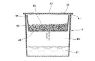
一方、前記容器ユニット4は、図2に示すように、容器本体40が上面が開放した全体或は一部が透明又は半透明の樹脂製によって成形され、上端を平坦な鍔状に成形された上縁部41となし、該上縁部41は通気・非透水性のシートからなる漏液防止手段42を用い、溶着、接着など適宜な方法で密封シールされる。
【0041】
容器本体40の内部には、樹脂製の中仕切り43が設けてあり、容器本体40と同様に鍔状に成形された上縁部を、容器本体40側面の突起部分44に引掛けて止められている。該中仕切り43には、塩化カルシウム、塩化マグネシウム、五酸化リンなどの潮解性の粒状の吸湿剤45が予め収容されて、容器本体40の中段に保持される。中仕切り43の底面及び側面には、穴若しくは溝状の滴下窓46が開いていり、潮解液47をスムーズに貯留室48へ溜める容器ユニット4が構成される。
【0042】
かかる構成の容器ユニット4にあって、開放している上面を塞いでいる漏液防止手段42は、通気・非透水性のシートからなるものであるから、湿気を含んだ周囲の空気は内部へ容易に流入する。内部には塩化カルシウム、塩化マグネシウム、五酸化リン等、空気中の水分を吸って自らは液化する所謂潮解性の吸湿剤45が収容されているので、流入した空気は湿気を取り除かれ、再び漏液防止手段42を透して外へ出ていく。すなわち、洋服タンスや下駄箱の空気を除湿する、所謂自然換気タイプの除湿器として作用するものである。
【0043】
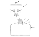
換気ユニット1と容器ユニット4との関係は、図3に示すように、換気ユニット1を容器ユニット4の上端部に着脱自在に設けられており、具体的には、換気ユニット1の脚部17を容器ユニット4の上縁部41に載せ、バンド2を用いる等適宜な方法で着脱自在に固定し、換気ユニット1のベルマウス状をした吸口14が容器ユニット4の天井面を覆う、漏液防止手段42に当接されるが、図3の状態で、洋服タンスに吊下げたり、容器ユニット4をそのまま下駄箱の棚に載せたりして使用する除湿器となる。
【0044】
すなわち、換気ユニット1を駆動すると、吸口14から容器ユニット4内の空気が漏液防止手段42を透して吸引されるので、容器ユニット4内の空気は希薄となり、漏液防止手段42の吸口14が当接してない部分を透して周囲の空気が流入する。つまり強制的換気タイプの除湿器として機能する。
【0045】
図4は第2の実施形態を示し、図1で示した換気ユニット1の接続口12に接続したベルマウス状をした吸口14に代え、可撓性のパイプやホースからなる可撓管3を接続し、当該可撓管3の先端に吸口14を接続して、容器ユニット4の漏液防止手段42に当接され、本発明の除湿器として使用される状況を示す。前例とは異なり、懸架具8は洋服タンス等に吊下げられるが、容器ユニット4は床や棚に置かれ、二つのユニットを分離して使用できる除湿器となる。
【0046】
本実施形態のように、分離して機能する除湿器の場合、前記第1の実施形態と違い万一押倒す力が加わっても、換気ユニット1の懸架具8によって吊下げられた状態の為に倒れ難いものである。また、モータやファン或は電池等の機能部品を収容する関係から、どうしても大型化せざるを得なかった強制換気タイプの除湿器に比べ、小型化出来て床面に対しての形状の自由度も増すものである。
【0047】
図5に本発明の第3の実施形態を示す。図2に示す第1の実施形態と異なる点は、漏液防止手段42に代えて、中央に丸穴の有る通気・非透水性のシートからなる外側漏液防止手段21で密封シールする点であり、平らな中仕切り43に代えて中央部を煙突状にシート面まで立上げ、通気管20を構成し、該通気管20の下端面を円形の通気・非透水性のシートからなる内側漏液防止手段22で密封シールした。かかる構成とすることによって、可撓性のパイプやホースからなる可撓管3の先端を、直接容器ユニット4に挿入して使用される除湿器となる。
【0048】
かかる構成によれば、容器ユニット4内の空気は、換気ユニット1で吸引され、内側漏液防止手段22を通過し可撓管3を経由して排気口16から排出されるが、同時に外側漏液防止手段21を通過して周囲の空気が流入するように作用する。このとき、図からも明らかな様に、空気は中仕切り43の外周や吸湿剤45の表面を舐めるように流れ、可撓管3の先端から吸引されていく。これは明らかに、第1、第2の実施形態よりも効率的に吸湿が行われることを示している。
【0049】
図6は第4の実施形態を示し、前記各実施形態では、換気ユニット1は繰返し使用可能であり、容器ユニット4は使い捨てを前提になされているが、この実施形態では容器ユニット60も繰り返し使用が可能なものである。
【0050】
すなわち、容器ユニット60は、容器本体61が透明或は半透明の樹脂又はガラスのブロー成形で製作される広口瓶の様に、螺合部を有する大きな開口部62と、比較的小口径のホース挿入口63を有する中空体であって、該挿入口63の内側に、ゴム等の可撓性で反発力の大きな材料からなる逆止弁64を備えている。この逆止弁64は、ゴムなど材料の反発力を利用したものでなくとも、例えばばね手段等で反発力を付勢しても同様な作用、効果が得られるものである。
【0051】
開口部62と螺合する樹脂製の蓋体65は、上面中央部分が大きく開口しており、該開口部分は蓋体65の裏面から通気・非透水性のシートからなる周縁に粘着剤を塗布した上面漏液防止手段66を張付けて閉止されている。樹脂製の中仕切り43は、鍔状に成形された上縁部の全周をパッキン67で包まれ、開口部62の口縁と上面漏液防止手段66を張付けた蓋体65とに挟まれ、収容し吸湿剤45を中段に保持し、反復使用容器ユニット60を構成している。換気ユニット1が図3及び図4で述べたものと同じもので、組合せて除湿器として機能することは言うまでもない。
【0052】
かかる構成の除湿器にあって、蓋体65を開けて中仕切り43に吸湿剤45を適量収容した上で蓋体65を閉める。その上で挿入口63に可撓管3の先端を挿入するが、この時容器を密閉していた逆止弁64が押し開けられ、内部の空気の出口が確保される。換気ユニット1を作動させて、容器の中の空気を吸引すると、図5で示した実施形態と同様に効率的な吸湿が行われるものである。吸湿剤45が殆ど潮解して、潮解液が溜まったら可撓管3を抜取り、蓋体65を開けて中仕切り43を取り出して潮解液を捨てる。その後、新しい吸湿剤45を補充して新たな使用を開始する。
【0053】
これによって、繰返し使用できる反復使用容器ユニット60が提供できるものである。
【0054】
本実施形態では、換気ユニット1は、懸架具8で強固に保持されるので転倒の恐れは全く無く、万一反復使用容器ユニット60が転倒した場合は、可撓管3が抜けてしまうので、直ちに逆止弁64が反発力で挿入口63を塞ぎ、潮解液の流出を防止するものである。
【0055】
また容器本体61と蓋体65の螺合部はパッキン67で漏液が防止されているので、万一倒れても螺合部から漏液する様なことはない。
【0056】
また空気の流入口となっている蓋体65の上面は、上面漏液防止手段66で漏液が防止されているので漏液することはないが、上面漏液防止手段66は通気・非透水性のシートで出来ているので、長く使用している中には、埃で目詰りを起こす心配が予想される。この様な場合には、粘着剤で貼付けられている上面漏液防止手段66を剥がし、新しい上面漏液防止手段66に交換すれば良く、繰返し使用できる反復使用容器ユニット60の提供には何の妨げにもならない。
【0057】
なお、前記各実施形態では、換気ユニットで容器ユニット内部の空気を吸引する説明を行っているが、吸気と排気を差し換えて空気の流れを全く逆にしても本発明の趣旨を逸脱するものではない。
【0058】
更に、本発明は吸湿剤を用いた除湿器であるが、例えば脱臭剤を用いる脱臭器、芳香剤を用いる芳香器、殺虫剤を用いる虫取り器などに利用することも可能である。
【0059】
【発明の効果】
以上説明した如く、本発明の除湿器によれば、自然換気タイプと強制換気タイプ夫々の長所を取入れたもので、除湿能力に優れると共に、安価で小型軽量化を実現できる。また、保守性の良く、汎用性の高いものである。
【図面の簡単な説明】
【図1】本発明の第1の実施形態に供される換気ユニットの内部を示す縦断面図である。
【図2】本実施形態に供される容器ユニットの内部を示す縦断面図である。
【図3】本実施形態の除湿器を示す側面図である。
【図4】本発明の第2の実施形態の除湿器を示す側面図である。
【図5】第3の実施形態に供される容器ユニットの内部を示す縦断面図である。
【図6】第4の実施形態の反復使用容器ユニットの内部を示す縦断面図である。
【符号の説明】
1…換気ユニット
3…可撓管
4…容器ユニット
6…モータ
7…電池
8…懸架具
9…ファン
10…吸口
20…通気管
21…外側漏液防止手段
22…内側漏液防止手段
40…容器本体
42…漏液防止手段
43…中仕切り
45…吸湿剤
60…反復使用容器ユニット
63…ホース挿入口
64…逆止弁
66…上面漏液防止手段[0001]
TECHNICAL FIELD OF THE INVENTION
The present invention relates to a dehumidifier using a deliquescent hygroscopic agent, and more particularly to a dehumidifier provided with forced ventilation means using an electric fan.
[0002]
[Prior art]
Conventionally, for example, in order to remove moisture in a storage space such as a closet at home, a clothes closet or a clog box, and to protect the stored items from damages such as molds, the liquid is sucked and liquefied. Various dehumidifiers using deliquescent absorbents such as calcium chloride, magnesium chloride, and phosphorus pentoxide have been used.
[0003]
These dehumidifiers are roughly classified into two types. One is a natural ventilation type in which the moisture is transferred from the air circulating by natural convection to the moisture absorbent, and the other is a forced ventilation type in which the fan is rotated by power to forcibly suck and exhaust air.
[0004]
As a known example of the former natural ventilation type, as described in
[0005]
Many other dehumidifiers using a deliquescent hygroscopic agent have been proposed and put into practical use, but have almost the same configuration. However, there are few examples of preventing spills simply by imparting viscosity to the deliquescent liquid with a thickener, and many natural ventilation type dehumidifiers as lids have breathability but prevent the exudation of moisture, In most cases, an air-permeable / water-impermeable sheet is used and the periphery is hermetically sealed to the container body.
[0006]
A known example of the latter forced-ventilation type is described in
[0007]
In such a configuration, as a result of the forced ventilation in which the air forcibly sucked and exhausted by the fan touches the dehumidifier, the dehumidifying ability is remarkably improved as compared with the natural ventilation type dehumidifier. However, in order to secure the air flow path, the opening is inevitable, and depending on the amount of deliquescent liquid that has accumulated in the container body when it is turned over, it overflows from the slightly narrowed opening and overflows to the outside. Will flow out.
[0008]
Therefore, recently, as in the conventional example described in
[0009]
That is, an intake port and an exhaust port are respectively provided at the left and right ends of the upper surface of the container main body which can be sealed, and both openings are opened and closed by a ventilation passage closing plate which acts as a seal. A rod-shaped movable body corresponding to a valve rod is fixed to the ventilation path closing plate, and the ventilation path closing plate is urged by a spring means in a direction to close the opening, and the tip of the movable body slightly extends from the bottom of the container body. It protrudes.
[0010]
Then, when the dehumidifier is correctly positioned, the movable body connected to the ventilation path closing plate is pushed up against the urging force of the spring means, and the intake port and the exhaust port are opened, so that the lid is closed. The forced ventilation of the provided fan works, and efficient dehumidification is performed.
[0011]
If the dehumidifier falls down, the movable body, which has been pushed in by the weight of the container body and opened the opening, returns to the original position by the spring urging force, so that the intake port and the exhaust port are closed, and the container is closed. The main body is in a sealed state to prevent the outflow of deliquescent liquid.
[0012]
[Patent Document 1]
Japanese Utility Model Publication No. 61-0093
[Patent Document 2]
Japanese Utility Model Application Laid-Open No. 2-61422 [0014]
[Patent Document 3]
JP 2000-334254 A
[Problems to be solved by the invention]
However, each of the two types has advantages and disadvantages, and the natural ventilation type dehumidifier has a relatively simple structure, can be manufactured at low cost, and can be disposable. There is a problem that the dehumidifying ability is extremely low. Also, recently, due to the increasing awareness of environmental issues, in the case of disposables, there are various ideas on the side of supplying the dehumidifier, such as devising a method to reduce the material of the discarded part and considering materials that do not cause environmental degradation. There is a problem that it is difficult to think of a standard one.
[0016]
On the other hand, in the forced-ventilation type dehumidifier, the air flow generated by turning the fan with a motor is passed from the separately provided intake port to the exhaust port, and the dehumidifier is increased. Openings are essential.
[0017]
Therefore, since it is necessary to prevent the deliquescent liquid from flowing out, a seal member must be provided at each opening, and the structure is inevitably complicated, and there is a disadvantage that the cost is extremely high as compared with the natural ventilation type.
[0018]
In addition, by using a refilling method for the absorbent, the only part to be discarded is the packaging of the dehumidifying agent for replenishment, which has the advantage of reducing the number of waste components and contributing to resource saving compared to the disposable method. Since the dehumidifying agent is exclusively used, there is a disadvantage that it is rather expensive.
[0019]
The present invention has been devised in view of the above-mentioned conventional technical problems, and incorporates the advantages of the two types, has excellent dehumidifying ability as a forced-ventilation type, and has a breathable and water-impermeable sheet even when it falls down. Like the closed natural ventilation type, the upper surface itself is a liquid leakage prevention means, or it is equipped with extremely simple and inexpensive liquid leakage prevention means, so that dehumidification performance is high, low cost, and replacement replacement An object of the present invention is to provide a dehumidifier excellent in versatility of a dehumidifier.
[0020]
[Means for Solving the Problems]
The present invention separates a lid portion containing a ventilation mechanism in a forced-ventilation type dehumidifier, which has conventionally been integrally formed, and a sealed container portion having a partition for containing a desiccant, a fan, a motor, and a battery. The lid part that contains the elements required for forced ventilation, such as, is integrated into an independent ventilation unit. On the other hand, conventionally, the closed container part, which is mainly located at the lower part of the lid part and mainly consists of a partition for storing the moisture absorbent and a storage part for storing the deliquescent liquid, The container is hermetically sealed with a sheet or an independent container unit provided with a liquid leakage prevention means such as one simple check valve.
[0021]
By adopting such a configuration, the present invention adopts a form in which an independent ventilation unit is located above a conventional natural ventilation type dehumidifier, and guides only one of intake or exhaust to the container unit, It is an object of the present invention to provide a forced-ventilation type dehumidifier which can reduce or simplify the means for preventing liquid leakage at the openings required at two places and reduce the cost while maintaining the dehumidifying performance.
[0022]
Specifically, in the present invention, a power source such as a dry battery is mounted on a resin housing, the motor is further fixed by a tightening means such as a screw, and an appropriate means such as press-fitting into a rotating shaft of the motor is adopted. A resin fan is mounted, and the rotating fan is configured so as to minimize the gap between the rotating fan and the casing and reduce leakage with a labyrinth structure or the like. Further, the casing may be provided with a connection port at the center thereof, which may be integral with or separate from the casing. For example, a bell mouth-shaped suction port or an otherwise flexible pipe or hose may be connected to the suction port. And At the position facing the outer periphery of the fan of the casing, an opening as wide as possible is secured and used as an exhaust port. Further, the casing has a concentric circular fitting structure, and is assembled concentrically with the resin casing to avoid contact with the casing whose gap is reduced as much as possible when the fan rotates. In order to attach the air supply / exhaust means configured as described above to a wall surface or a ceiling surface, a metal or resin suspension device is provided, and a ventilation unit is configured and disposed above the dehumidifying unit. A magnet, a magic tape (registered trademark), or the like may be appropriately used as the suspension tool.
[0023]
On the other hand, a transparent or translucent resin container having an open upper surface is formed with a flat flange at the upper edge, and the upper edge is sealed with a liquid leakage preventing means made of a gas-permeable and water-impermeable sheet. Although it is sealed and covers the upper surface, a resin partition is also provided immediately below the liquid leakage preventing means, and the partition has a hole or groove for deliquescent droplets on the bottom surface, and calcium chloride , Magnesium chloride, phosphorus pentoxide, etc., constitute a storage section for deliquescent hygroscopic agents. The deliquescent moisture absorbent is stored in the partition beforehand before being hermetically sealed. In most cases, a natural ventilation type dehumidifier that is supposed to be completely disposed of and a container unit having the same configuration are arranged near the ventilation unit, and both functions as a dehumidifier.
[0024]
That is, the housing of the ventilation unit is placed on the upper edge of the container unit, and both units are fixed by an appropriate method such as banding. At this time, the bell mouth-shaped intake port of the ventilation unit is If the fan is driven so as to contact the liquid leakage prevention means covering the upper surface of the container, the liquid leakage prevention means has air permeability, so that the air inside the container unit is sucked from the part where the intake port contacts, Air containing moisture flows into the container unit from the portion. In other words, the surrounding air around the deliquescent moisture absorbent is forcibly ventilated, so that a container unit having the same configuration as a natural ventilation type dehumidifier can achieve the same dehumidifying capacity as a forced ventilation type. In addition, assuming a fall, the top surface of the container unit is covered with a ventilating / non-permeable liquid leakage preventing means, so that the deliquescent liquid does not flow out similarly to the natural ventilation type.
[0025]
In addition, as described in the previous section, the present invention sucks air inside the container unit through the air-impermeable and water-impermeable sheet acting as a liquid leakage preventing means by the power of the fan. However, the dehumidifying effect is still obtained, and of course, the deliquescent liquid does not flow out.
[0026]
Further, in the present invention, a bell mouth-shaped intake port of the ventilation unit is replaced with a connection port for connecting a flexible pipe or hose, and a flexible pipe or hose of a required length is connected to the connection port. Further, the tip is detachably attached to the container unit.
[0027]
That is, if the shape of the tip is a bell mouth and it comes into contact with the liquid leakage prevention means that covers the upper surface of the container unit, the above-described case of the ventilation unit is placed on the upper edge of the container unit, and a band is formed. The same operation and effect can be obtained as when both units are fixed by an appropriate method such as hanging.
[0028]
Next, to describe a method for easily attaching the tip of a flexible pipe or hose to the container unit, the central part of the partition of the container unit is formed into a hollow cylindrical shape to form an intake pipe. The upper end surface of the intake pipe is at the same height as the upper edge of the container unit, and is tightly sealed with a gas-permeable / non-permeable sheet. Instead, the lower end surface of the intake pipe is tightly sealed with a gas-permeable / water-impermeable sheet. That is, there is a cylindrical hole in a part of the upper surface of the natural ventilation type dehumidifier, the hole is an outlet of the intake pipe, and the inlet side is tightly sealed. If the tip of a flexible pipe or hose is inserted tightly into this intake pipe so that it does not come off easily, the above-mentioned ventilation unit housing is placed on the upper edge of the container unit and banded. The same operation and effect as when the two units are fixed by an appropriate method can be obtained.
[0029]
Instead of the container unit having a disposable structure described so far, a container unit to be used repeatedly will be described. The container body has a wide-mouth bottle shape, and a large-diameter packing lid is screwed. And sealed. The lid is formed in a donut shape having a hole at the center, and the hole at the center is closed by a gas-permeable and water-impermeable sheet having a strong adhesive applied to the periphery. A middle partition for storing the dehumidifying agent is provided at the middle stage inside the container body, and refilling and replacement is performed from the wide mouth of the bottle-shaped container. An inlet for inserting the tip of a flexible pipe or hose is provided at the shoulder of the jar-shaped container body. In view of the above, liquid leakage prevention means for preventing outflow of deliquescence is required.
[0030]
In the present invention, a rubber check valve is provided which is pushed open at the tip when a flexible tube or tube is inserted and closes the opening when the tube is removed. If a container unit and a ventilation unit that are repeatedly used with such an idea are used in combination, the casing of the ventilation unit is placed on the upper edge of the container unit and a suitable method such as banding is used. The same operation and effect as when both units are fixed can be obtained.
[0031]
In the device of the preceding paragraph, the horizontal cross-sectional shape is basically a circular container body. However, as described for the container main body with a horizontal cross-sectional shape, it is configured such that the intake port is provided at the sharp end of the droplet shape. Thus, when the flexible pipe or hose comes off and falls down, the opening is always on the upper side as in the case of rising and spilling, so that the outflow of deliquescent liquid can be prevented.
[0032]
BEST MODE FOR CARRYING OUT THE INVENTION
Hereinafter, embodiments of the present invention will be described with reference to the drawings. FIG. 1 shows a vertical section of the
[0033]
The upper surface of the
[0034]
The back surface of the
[0035]
Further, the surface of the
[0036]
The outer periphery of the casing 11 has a circular shape, and is fitted to the
[0037]
The
[0038]
The lower half of the
[0039]
In the
[0040]
On the other hand, as shown in FIG. 2, the whole or a part of the container
[0041]
A
[0042]
In the
[0043]
As shown in FIG. 3, the relationship between the
[0044]
That is, when the
[0045]
FIG. 4 shows a second embodiment, in which a bell mouth-shaped
[0046]
In the case of the dehumidifier that functions separately as in the present embodiment, unlike the first embodiment, even if a pushing force is applied, the dehumidifier is suspended by the suspension tool 8 of the
[0047]
FIG. 5 shows a third embodiment of the present invention. The difference from the first embodiment shown in FIG. 2 is that instead of the liquid
[0048]
According to such a configuration, the air in the
[0049]
FIG. 6 shows a fourth embodiment. In each of the above embodiments, the
[0050]
That is, the
[0051]
The
[0052]
In the dehumidifier having such a structure, the
[0053]
Thus, a
[0054]
In this embodiment, since the
[0055]
Moreover, since the liquid leakage is prevented by the packing 67 at the screwed portion between the
[0056]
The upper surface of the
[0057]
In each of the above embodiments, the description has been made in which the ventilation unit sucks the air inside the container unit. However, even if the air flow is completely reversed by replacing the intake air and the exhaust air, the invention does not depart from the gist of the present invention. Absent.
[0058]
Furthermore, the present invention relates to a dehumidifier using a hygroscopic agent. However, the present invention can be applied to, for example, a deodorizer using a deodorant, an aroma device using an aromatic agent, and a insect trap using an insecticide.
[0059]
【The invention's effect】
As described above, according to the dehumidifier of the present invention, the advantages of each of the natural ventilation type and the forced ventilation type are adopted, so that the dehumidifier is excellent in dehumidification ability, and can be realized at low cost and small size and light weight. Further, it is easy to maintain and highly versatile.
[Brief description of the drawings]
FIG. 1 is a longitudinal sectional view showing the inside of a ventilation unit provided in a first embodiment of the present invention.
FIG. 2 is a longitudinal sectional view showing the inside of the container unit provided in the present embodiment.
FIG. 3 is a side view showing the dehumidifier of the embodiment.
FIG. 4 is a side view showing a dehumidifier according to a second embodiment of the present invention.
FIG. 5 is a longitudinal sectional view showing the inside of a container unit provided in a third embodiment.
FIG. 6 is a longitudinal sectional view showing the inside of a reusable container unit according to a fourth embodiment.
[Explanation of symbols]
DESCRIPTION OF
Claims (8)
前記容器ユニットに連通状態に取り付けられて、吸排気手段により前記容器本体の内部空気を強制的に入れ替えて、前記吸湿剤により湿気を吸収する換気ユニットとを備えた除湿器であって、
前記換気ユニットを、前記容器ユニットに漏液防止手段を介して着脱自在に設けたことを特徴とする除湿器。Inside the container body, a container unit provided with a partition for storing a deliquescent hygroscopic agent and a space for storing the deliquescent liquid liquefied by the hygroscopic agent below,
A dehumidifier comprising a ventilation unit which is attached to the container unit in a communicating state, forcibly replaces the internal air of the container main body by a suction / exhaust unit, and absorbs moisture by the desiccant.
A dehumidifier, wherein the ventilation unit is detachably provided to the container unit via a liquid leakage prevention unit.
前記容器ユニットに連通状態に取り付けられて、吸排気手段により前記容器本体の内部空気を強制的に入れ替えて、前記吸湿剤により湿気を吸収する換気ユニットとを備えた除湿器の使用方法であって、
前記換気ユニットを、前記容器ユニットに漏液防止手段を介して着脱自在に設けた、前記換気ユニットの不使用時には、前記容器ユニット単独で自然換気タイプの除湿器として使用することを特徴とする除湿器の使用方法。Inside the container body, a container unit provided with a partition for containing a deliquescent hygroscopic agent and a space for storing the deliquescent liquid liquefied by the hygroscopic agent below,
A method of using a dehumidifier, comprising: a ventilation unit that is attached to the container unit in communication with the container unit, forcibly replaces the internal air of the container body by suction and exhaust means, and absorbs moisture by the desiccant. ,
The dehumidifying unit, wherein the ventilation unit is detachably provided in the container unit via a liquid leakage preventing means. When the ventilation unit is not used, the container unit is used alone as a natural ventilation type dehumidifier. How to use the container.
Priority Applications (1)
| Application Number | Priority Date | Filing Date | Title |
|---|---|---|---|
| JP2002353319A JP2004181404A (en) | 2002-12-05 | 2002-12-05 | Dehumidifier |
Applications Claiming Priority (1)
| Application Number | Priority Date | Filing Date | Title |
|---|---|---|---|
| JP2002353319A JP2004181404A (en) | 2002-12-05 | 2002-12-05 | Dehumidifier |
Publications (1)
| Publication Number | Publication Date |
|---|---|
| JP2004181404A true JP2004181404A (en) | 2004-07-02 |
Family
ID=32754628
Family Applications (1)
| Application Number | Title | Priority Date | Filing Date |
|---|---|---|---|
| JP2002353319A Pending JP2004181404A (en) | 2002-12-05 | 2002-12-05 | Dehumidifier |
Country Status (1)
| Country | Link |
|---|---|
| JP (1) | JP2004181404A (en) |
Cited By (3)
| Publication number | Priority date | Publication date | Assignee | Title |
|---|---|---|---|---|
| US7927406B2 (en) | 2007-06-01 | 2011-04-19 | Denso Corporation | Water droplet generating system and method for generating water droplet |
| WO2013039098A1 (en) * | 2011-09-16 | 2013-03-21 | Hishida Iwao | Method and apparatus for obtaining water from air |
| GB2609247A (en) * | 2021-07-27 | 2023-02-01 | Kontrol Group Ltd | Novel multipurpose fast dehumidification device |
-
2002
- 2002-12-05 JP JP2002353319A patent/JP2004181404A/en active Pending
Cited By (5)
| Publication number | Priority date | Publication date | Assignee | Title |
|---|---|---|---|---|
| US7927406B2 (en) | 2007-06-01 | 2011-04-19 | Denso Corporation | Water droplet generating system and method for generating water droplet |
| WO2013039098A1 (en) * | 2011-09-16 | 2013-03-21 | Hishida Iwao | Method and apparatus for obtaining water from air |
| JP5252141B1 (en) * | 2011-09-16 | 2013-07-31 | 巌 菱田 | Method and apparatus for obtaining water from air |
| GB2609247A (en) * | 2021-07-27 | 2023-02-01 | Kontrol Group Ltd | Novel multipurpose fast dehumidification device |
| GB2609247B (en) * | 2021-07-27 | 2023-08-02 | Kontrol Group Ltd | Multipurpose air treatment device |
Similar Documents
| Publication | Publication Date | Title |
|---|---|---|
| KR101806990B1 (en) | A Reusable Dehumidifying Container | |
| JP2004181404A (en) | Dehumidifier | |
| JP2007322018A (en) | Humidifier | |
| JPH0746341Y2 (en) | Moisture absorber | |
| JP6258818B2 (en) | Deodorization storage | |
| JP4084877B2 (en) | Dehumidifier | |
| JP3944840B2 (en) | Rotary drug diffusion device | |
| JP2502972Y2 (en) | Moisture absorber | |
| JP4123414B2 (en) | Drug diffusion device | |
| JPS6326176Y2 (en) | ||
| JP3825855B2 (en) | Dehumidifier | |
| CN218307142U (en) | Novel dehumidification bag | |
| JP2002204824A (en) | Deodorizer and shoe cabinet with the deodorizer | |
| JP2002147936A (en) | Deodorizing and sterilizing device for refrigerator | |
| JP5439712B2 (en) | Air cleaner | |
| JP2548886Y2 (en) | Dehumidifier | |
| CN207168761U (en) | A kind of sterilizing deodoring attachment device of electric fan | |
| KR200359684Y1 (en) | Reagent cabinet having a moisture absorbent | |
| JP2565332Y2 (en) | Deodorizing filter and deodorizing device | |
| JP2005052816A (en) | Dehumidifier | |
| JPS601712Y2 (en) | air purifier | |
| JP2022026258A (en) | Display case | |
| KR200178053Y1 (en) | Apparatus for removing dust having function of humidification | |
| JP3050910U (en) | Deodorizer | |
| JPH086487Y2 (en) | Deodorizer |