【0001】
【発明の属する技術分野】
本発明は、携帯電話機などの携帯可能な電子機器に搭載されるスピーカの取り付け構造に関するものである。
【0002】
【従来の技術】
近年、携帯電話機においては、益々小型化、薄型化が進んでいるが、この様な携帯電話機においても、高い音質で音を発生させるスピーカが開発されており、スピーカの能力を最大限に発揮させることの出来るスピーカ取り付け構造が要求されている。
【0003】
従来の携帯電話機のスピーカ取り付け構造においては、図8に示す如く、キャビネット半体(9)の内面にスピーカ設置面(91)が形成されており、該スピーカ設置面(91)には、図9に示す如く、スピーカ(8)から発生する音波を通過させるための複数の放音孔(94)が、スピーカ設置面(91)の中央部を貫通して形成されると共に、該放音孔(94)を包囲して、防塵ネット(84)をスピーカ設置面(91)に貼着するための接着面(95)が設けられている。
【0004】
キャビネット半体(9)に対するスピーカ(8)の取り付け工程においては、図8及び図10に示す如く、先ず防塵ネット(84)の外周部をスピーカ設置面(91)の接着面(95)に接着して、防塵ネット(84)をスピーカ設置面(91)に固定する。これによって、キャビネット半体(9)の放音孔(94)は防塵ネット(84)により覆われることになる。その後、防塵ネット(84)の上に、リング状クッション(83)を介してスピーカ(8)を設置し、該スピーカ(8)をキャビネット半体(9)に固定する(特許文献1参照)。
【0005】
尚、防塵ネットは、防塵及び防水のためのメッシュ構造を有しているが、近年のスピーカ性能の向上に伴う高磁力化による磁性分の吸着に対して十分な防塵性能を発揮させるべく、防塵ネットのメッシュは極めて細かくなってきている。例えば、直径が15mm〜18mm程度のスピーカにおいては、メッシュのオープニング径が55μm以下の防塵ネットが採用されている。
【0006】
【特許文献1】
特開平11−4493号公報
【0007】
【発明が解決しようとする課題】
しかしながら、図8に示す上記特許文献1の携帯電話機のスピーカ取り付け構造においては、上述の如くメッシュの細かい防塵ネット(84)を採用した場合、防塵ネット(84)が、スピーカ(8)からの音波を受けて、メッシュの密度に応じた特定の周波数帯域(600Hz〜1200Hz)で振動し、これに伴って防塵シート(84)がスピーカ設置面(91)に衝突して、異音が発生する問題があった。
【0008】
上記異音の発生を回避するためには、キャビネット半体(9)のスピーカ設置面(91)の放音孔(94)の近傍位置まで防塵シート(84)を貼着することが有効であるが、放音孔(94)の輪郭に沿って接着剤を塗布することは技術的に困難であり、組立工程の作業性が悪化するばかりでなく、放音孔(94)に接着剤がはみ出して、放音孔(94)を塞いでしまう虞がある。
【0009】
そこで本発明の目的は、スピーカからの音波を受けて防塵シートが振動したとしても異音が発生することがなく、然も組立工程の作業性が良好な携帯型電子機器のスピーカ取り付け構造を提供することである。
【0010】
【課題を解決する為の手段】
本発明に係る携帯型電子機器のスピーカ取り付け構造においては、キャビネットの内面に形成されたスピーカ設置面(41)に、1或いは複数の放音孔(44)が開設され、該スピーカ設置面(41)には、防塵ネット(84)が外周部をキャビネット内面に接合されて配置され、該防塵ネット(84)に対向させて、スピーカ(8)が取り付けられている。
キャビネットのスピーカ設置面(41)と防塵ネット(84)の間には、スピーカ(8)の鳴動に伴って振動する防塵ネット(84)の中央部に対してスピーカ設置面(41)を非接触に保つための空隙Cが設けられている。
【0011】
上記本発明の携帯型電子機器のスピーカ取り付け構造においては、スピーカ(8)から発生する音波を受けて防塵ネット(84)が振動した場合、該防塵ネット(84)は、中央部にて最大振幅を発生するが、該中央部とスピーカ設置面(41)との間には空隙Cが形成されているので、防塵ネット(84)が振動に伴ってスピーカ設置面(41)に衝突することはない。
【0012】
又、上記本発明の携帯型電子機器のスピーカ取り付け構造においては、防塵ネット(84)の外周部のみをキャビネットの内面に接合すればよいので、従来の如く、スピーカ設置面(41)の放音孔(44)の輪郭に沿って接着剤を塗布する必要がなく、これによって、組立工程の作業性が改善されるばかりでなく、接着剤のはみ出しにより放音孔(44)が塞がれることはない。
【0013】
具体的構成においては、キャビネットのスピーカ設置面(41)には、防塵ネット(84)の貼着面よりもスピーカ(8)側に突出する1或いは複数の凸部(43)が形成され、該凸部(43)によって防塵ネット(84)の中央部がスピーカ設置面(41)から持ち上げられて、該中央部とスピーカ設置面(41)との間に前記空隙Cが形成されている。
【0014】
該具体的構成において、防塵ネット(84)は、キャビネット内面に接合された外周部と凸部(43)によって支持された部分とを固定端として、中央部が振動する。ここで、凸部(43)をスピーカ設置面(41)上の最も適切な位置に形成することによって、防塵ネット(84)の振幅を最小化することが出来、これに伴って凸部(43)の高さを低く形成することが可能である。これによって、防塵ネット(84)に皺が寄ることを防止することが出来る。
【0015】
【発明の効果】
本発明に係る携帯型電子機器のスピーカ取り付け構造によれば、スピーカの鳴動に伴う異音の発生を防止することが出来ると共に、組立工程の作業性を改善することが出来る。
【0016】
【発明の実施の形態】
以下、本発明を折り畳み式携帯電話機に実施した形態につき、図面に沿って具体的に説明する。
本発明に係る折り畳み式携帯電話機は、図1に示す如く、操作側キャビネット(1)と表示側キャビネット(2)をヒンジ機構(3)を介して互いに連結して構成されている。操作側キャビネット(1)は、背面キャビネット半体(4)と前面キャビネット半体(5)とを接合して構成され、該操作側キャビネット(1)に複数の操作キー(11)が配列されると共に、送話部(12)が設けられている。又、表示側キャビネット(2)は、前面キャビネット半体(6)と背面キャビネット半体(7)を接合して構成され、該表示側キャビネット(2)にメインディスプレイ(21)が配備されると共に、受話部(22)が設けられている。
又、図2に示す如く、操作側キャビネット(1)の背面には、電池蓋(14)が取り付けられており、該電池蓋(14)の上方部にはスピーカ放音部(13)が形成されている。一方、表示側キャビネット(2)の背面には、サブディスプレイ(23)とCCDカメラ(24)が配備されている。
【0017】
図3に示す如く、操作側キャビネット(1)の背面キャビネット半体(4)には、前記スピーカ放音部(13)の内面に、着信報知用のスピーカ(8)を設置するためのスピーカ設置面(41)が形成されている。該スピーカ設置面(41)には、キャビネット外部からの塵や水の侵入を防ぐための防塵ネット(84)が設置され、該防塵ネット(84)上に、リング状クッション(83)を介してスピーカ(8)が設置される。
【0018】
図4及び図5に示す如く、背面キャビネット(4)のスピーカ設置面(41)には、スピーカ(8)から発生する音波を通過させるための複数の放音孔(44)が、スピーカ設置面(41)の中央部を貫通して開設されている。又、スピーカ設置面(41)の外周部には、防塵ネット(84)の外周部を貼着するための接着面(45)が形成されている。
更に、図5及び図6に示す如く、背面キャビネット(4)のスピーカ設置面(41)の中央部には、中心位置の放音孔(44)の周囲4箇所にそれぞれ0.2mm〜0.5mmの高さを有する凸部(43)が形成されている。
【0019】
背面キャビネット半体(4)にスピーカ(8)を取り付ける工程においては、図7に示す如く、先ず防塵ネット(84)の外周部をスピーカ設置面(41)の接着面(45)に接着して、防塵ネット(84)をスピーカ設置面(41)に固定する。これによって、防塵ネット(84)は、中央部がスピーカ設置面(41)の凸部(43)によって突き上げられ、該防塵ネット(84)の中心部はスピーカ設置面(41)から持ち上げられる。この結果、防塵ネット(84)とスピーカ設置面(41)との間は、凸部(43)の高さに応じた空隙Cが形成されることになる。
その後、防塵ネット(84)の上にリング状クッション(83)を介してスピーカ(8)を設置し、該スピーカ(8)を周知の係止構造によってキャビネット半体(4)に固定する。
【0020】
上記本発明の折り畳み式携帯電話機においては、スピーカ(8)から発生する音波を受けて防塵ネット(84)が振動した場合、該防塵ネット(84)は中央部にて最大振幅を発生するが、該中央部とスピーカ設置面(41)との間には前記空隙Cが設けられているので、防塵ネット(84)が振動に伴ってスピーカ設置面(41)に衝突することはない。これによって、スピーカ鳴動時の異音の発生が防止される。
【0021】
又、上記本発明の折り畳み式携帯電話機のスピーカ取り付け構造によれば、防塵ネット(84)の外周部のみを背面キャビネット半体(4)の内面に貼着すればよいので、従来の如く、スピーカ設置面(41)の放音孔(44)の輪郭に沿って接着剤を塗布する必要がなく、これによって、組立工程の作業性が改善されるばかりでなく、接着剤のはみ出しにより放音孔(44)が塞がれることはない。
【0022】
尚、本発明の各部構成は上記実施の形態に限らず、特許請求の範囲に記載の技術的範囲内で種々の変形が可能である。例えば、背面キャビネット半体(4)のスピーカ設置面(41)に凸部(43)を形成する構成に限らず、スピーカ設置面(41)の中央部に凹部を形成することによって、防塵ネット(84)とスピーカ設置面(41)の間に空隙を形成する構成も採用可能である。
又、複数の凸部(43)に代えて、スピーカ設置面(41)の中央部の放音孔(44)を包囲してリング状の凸条部を形成した構成によっても、上記実施例と同等の効果が得られる。
【図面の簡単な説明】
【図1】本発明に係る折り畳み式携帯電話機の斜視図である。
【図2】該折り畳み式携帯電話機を裏返して示す斜視図である。
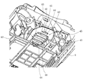
【図3】操作側キャビネットの背面キャビネット半体の内部構造を示す分解斜視図である。
【図4】背面キャビネット半体の要部を示す拡大斜視図である。
【図5】同上の平面図である。
【図6】図5のA−A線に沿う断面図である。
【図7】スピーカ設置面にスピーカを設置した状態を示す断面図である。
【図8】従来の携帯電話機におけるキャビネット半体の内部構造を示す分解斜視図である。
【図9】該携帯電話機のキャビネット半体の要部を拡大して示す平面図である。
【図10】該携帯電話機のスピーカ設置面にスピーカが設置されている状態を示す断面図である。
【符号の説明】
(1) 操作側キャビネット
(13) スピーカ放音部
(2) 表示側キャビネット
(3) ヒンジ機構
(4) 背面キャビネット半体
(41) スピーカ設置面
(43) 凸部
(44) 放音孔
(45) 接着面
(5) 前面キャビネット半体
(6) 前面キャビネット半体
(7) 背面キャビネット半体
(8) スピーカ
(83) リング状クッション
(84) 防塵ネット[0001]
TECHNICAL FIELD OF THE INVENTION
The present invention relates to a speaker mounting structure mounted on a portable electronic device such as a mobile phone.
[0002]
[Prior art]
In recent years, the size and thickness of mobile phones have been increasingly reduced, and even in such mobile phones, speakers that generate sound with high sound quality have been developed, and the capabilities of the speakers are maximized. There is a demand for a speaker mounting structure that can be used.
[0003]
In the conventional speaker mounting structure for a mobile phone, as shown in FIG. 8, a speaker mounting surface (91) is formed on the inner surface of a cabinet half (9). As shown in FIG. 5, a plurality of sound emission holes (94) for passing sound waves generated from the speaker (8) are formed through the center of the speaker installation surface (91), and the sound emission holes (94) are formed. An adhering surface (95) for adhering the dust-proof net (84) to the speaker mounting surface (91) is provided surrounding the (94).
[0004]
In the process of attaching the speaker (8) to the cabinet half (9), first, as shown in FIGS. 8 and 10, the outer peripheral portion of the dustproof net (84) is bonded to the bonding surface (95) of the speaker mounting surface (91). Then, the dustproof net (84) is fixed to the speaker installation surface (91). As a result, the sound emission hole (94) of the cabinet half (9) is covered with the dustproof net (84). Thereafter, a speaker (8) is installed on the dustproof net (84) via a ring-shaped cushion (83), and the speaker (8) is fixed to the cabinet half (9) (see Patent Document 1).
[0005]
The dust-proof net has a mesh structure for dust-proofing and waterproofing. However, in order to exhibit sufficient dust-proofing performance against the adsorption of magnetic components due to the high magnetic force accompanying the recent improvement in speaker performance, dust-proofing is required. Net meshes are becoming extremely fine. For example, in a speaker having a diameter of about 15 mm to 18 mm, a dustproof net having a mesh opening diameter of 55 μm or less is employed.
[0006]
[Patent Document 1]
JP-A-11-4493
[Problems to be solved by the invention]
However, in the speaker mounting structure of the mobile phone of Patent Document 1 shown in FIG. 8, when the dust-proof net (84) having a fine mesh is employed as described above, the dust-proof net (84) causes sound waves from the speaker (8). In response to this, the vibration occurs in a specific frequency band (600 Hz to 1200 Hz) according to the density of the mesh, and the dustproof sheet (84) collides with the speaker installation surface (91), thereby generating abnormal noise. was there.
[0008]
In order to avoid the generation of the abnormal noise, it is effective to attach the dustproof sheet (84) to a position near the sound emission hole (94) of the speaker installation surface (91) of the cabinet half (9). However, it is technically difficult to apply the adhesive along the contour of the sound output hole (94), which not only deteriorates the workability of the assembling process, but also protrudes the adhesive into the sound output hole (94). Therefore, there is a possibility that the sound emission hole (94) may be closed.
[0009]
Accordingly, an object of the present invention is to provide a speaker mounting structure of a portable electronic device which does not generate abnormal noise even when the dustproof sheet vibrates in response to a sound wave from the speaker and has good workability in an assembling process. It is to be.
[0010]
[Means for solving the problem]
In the speaker mounting structure for a portable electronic device according to the present invention, one or a plurality of sound emission holes (44) are formed in the speaker mounting surface (41) formed on the inner surface of the cabinet, and the speaker mounting surface (41) is provided. ), A dustproof net (84) is arranged with its outer peripheral portion joined to the inner surface of the cabinet, and a speaker (8) is attached to face the dustproof net (84).
Between the speaker installation surface (41) of the cabinet and the dust-proof net (84), the speaker installation surface (41) is not in contact with the center of the dust-proof net (84) vibrating with the sound of the speaker (8). A gap C is provided to keep the distance C.
[0011]
In the above-described speaker mounting structure of the portable electronic device of the present invention, when the dust-proof net (84) vibrates by receiving a sound wave generated from the speaker (8), the dust-proof net (84) has a maximum amplitude at the center. However, since a gap C is formed between the center portion and the speaker installation surface (41), the dustproof net (84) may not collide with the speaker installation surface (41) due to vibration. Absent.
[0012]
Further, in the speaker mounting structure of the portable electronic device of the present invention, only the outer peripheral portion of the dustproof net (84) needs to be joined to the inner surface of the cabinet. There is no need to apply the adhesive along the contour of the hole (44), which not only improves the workability of the assembling process, but also closes the sound emission hole (44) due to the protrusion of the adhesive. There is no.
[0013]
In a specific configuration, the speaker installation surface (41) of the cabinet is formed with one or a plurality of protrusions (43) projecting toward the speaker (8) from the attachment surface of the dustproof net (84). The central portion of the dustproof net (84) is lifted from the speaker mounting surface (41) by the convex portion (43), and the gap C is formed between the central portion and the speaker mounting surface (41).
[0014]
In this specific configuration, the dust-proof net (84) has a central portion that vibrates with an outer peripheral portion joined to the inner surface of the cabinet and a portion supported by the convex portion (43) as fixed ends. Here, by forming the convex portion (43) at the most appropriate position on the speaker installation surface (41), the amplitude of the dust-proof net (84) can be minimized. ) Can be formed low. As a result, it is possible to prevent the dust-proof net (84) from wrinkling.
[0015]
【The invention's effect】
ADVANTAGE OF THE INVENTION According to the speaker mounting structure of the portable electronic device which concerns on this invention, generation | occurrence | production of the abnormal sound accompanying the sound of a speaker can be prevented, and the workability | operativity of an assembly process can be improved.
[0016]
BEST MODE FOR CARRYING OUT THE INVENTION
Hereinafter, embodiments of the present invention applied to a foldable mobile phone will be specifically described with reference to the drawings.
As shown in FIG. 1, the foldable mobile phone according to the present invention is configured by connecting an operation side cabinet (1) and a display side cabinet (2) to each other via a hinge mechanism (3). The operation side cabinet (1) is configured by joining a rear cabinet half (4) and a front cabinet half (5), and a plurality of operation keys (11) are arranged in the operation side cabinet (1). In addition, a transmission section (12) is provided. The display cabinet (2) is formed by joining a front cabinet half (6) and a rear cabinet half (7), and a main display (21) is provided in the display cabinet (2). , An earpiece (22).
As shown in FIG. 2, a battery cover (14) is attached to the back of the operation side cabinet (1), and a speaker sound emitting section (13) is formed above the battery cover (14). Have been. On the other hand, a sub-display (23) and a CCD camera (24) are provided on the back of the display cabinet (2).
[0017]
As shown in FIG. 3, on the rear cabinet half (4) of the operation side cabinet (1), a speaker installation for installing an incoming call announcement speaker (8) on the inner surface of the speaker sound emission section (13). A surface (41) is formed. A dustproof net (84) for preventing dust and water from entering from outside the cabinet is installed on the speaker installation surface (41), and a ring-shaped cushion (83) is provided on the dustproof net (84). A speaker (8) is installed.
[0018]
As shown in FIGS. 4 and 5, a plurality of sound emission holes (44) for passing sound waves generated from the speakers (8) are provided on the speaker installation surface (41) of the rear cabinet (4). It is opened through the center of (41). Further, an adhesive surface (45) for attaching an outer peripheral portion of the dustproof net (84) is formed on an outer peripheral portion of the speaker installation surface (41).
Further, as shown in FIG. 5 and FIG. 6, in the center of the speaker installation surface (41) of the rear cabinet (4), 0.2 mm to 0.2 mm is provided at four places around the central sound output hole (44). A projection (43) having a height of 5 mm is formed.
[0019]
In the step of attaching the speaker (8) to the rear cabinet half (4), as shown in FIG. 7, first, the outer peripheral portion of the dustproof net (84) is bonded to the bonding surface (45) of the speaker mounting surface (41). Then, the dustproof net (84) is fixed to the speaker installation surface (41). Accordingly, the center of the dust-proof net (84) is pushed up by the protrusion (43) of the speaker installation surface (41), and the center of the dust-proof net (84) is lifted from the speaker installation surface (41). As a result, a gap C corresponding to the height of the projection (43) is formed between the dustproof net (84) and the speaker installation surface (41).
Then, the speaker (8) is set on the dustproof net (84) via the ring-shaped cushion (83), and the speaker (8) is fixed to the cabinet half (4) by a well-known locking structure.
[0020]
In the foldable mobile phone of the present invention, when the dust-proof net (84) vibrates in response to a sound wave generated from the speaker (8), the dust-proof net (84) generates a maximum amplitude at the center portion. Since the gap C is provided between the center portion and the speaker installation surface (41), the dustproof net (84) does not collide with the speaker installation surface (41) due to vibration. As a result, generation of abnormal noise when the speaker is sounded is prevented.
[0021]
Further, according to the speaker mounting structure of the foldable portable telephone of the present invention, only the outer peripheral portion of the dustproof net (84) needs to be attached to the inner surface of the rear cabinet half (4). It is not necessary to apply the adhesive along the contour of the sound emission hole (44) of the installation surface (41), which not only improves the workability of the assembling process, but also allows the sound emission hole to be formed due to the protrusion of the adhesive. (44) will not be blocked.
[0022]
The configuration of each part of the present invention is not limited to the above embodiment, and various modifications can be made within the technical scope described in the claims. For example, the dustproof net (4) is not limited to the configuration in which the convex portion (43) is formed on the speaker mounting surface (41) of the rear cabinet half (4), but the concave portion is formed in the center portion of the speaker mounting surface (41). A configuration in which a gap is formed between the speaker mounting surface (84) and the speaker mounting surface (41) can also be adopted.
Further, instead of the plurality of convex portions (43), a ring-shaped convex portion may be formed so as to surround the sound emission hole (44) at the center of the speaker installation surface (41). An equivalent effect can be obtained.
[Brief description of the drawings]
FIG. 1 is a perspective view of a foldable mobile phone according to the present invention.
FIG. 2 is a perspective view showing the flip-type mobile phone upside down.
FIG. 3 is an exploded perspective view showing an internal structure of a rear cabinet half of the operation side cabinet.
FIG. 4 is an enlarged perspective view showing a main part of the rear cabinet half.
FIG. 5 is a plan view of the same.
FIG. 6 is a sectional view taken along line AA of FIG.
FIG. 7 is a cross-sectional view showing a state where a speaker is installed on a speaker installation surface.
FIG. 8 is an exploded perspective view showing the internal structure of a cabinet half in a conventional mobile phone.
FIG. 9 is an enlarged plan view showing a main part of a half cabinet of the mobile phone.
FIG. 10 is a cross-sectional view showing a state where a speaker is installed on a speaker installation surface of the mobile phone.
[Explanation of symbols]
(1) Operation side cabinet (13) Speaker emission part (2) Display side cabinet (3) Hinge mechanism (4) Rear cabinet half (41) Speaker installation surface (43) Convex part (44) Sound emission hole (45) Adhesive surface (5) Front cabinet half (6) Front cabinet half (7) Rear cabinet half (8) Speaker (83) Ring cushion (84) Dustproof net