【0001】
【発明の属する技術分野】
本発明は光記録媒体に係り、再生装置の回転保持部にクランプされるクランプを中央に有しこの周囲にスパイラル状又は同心円状の記録トラックが形成された記録保持部を有する光記録媒体の改良に関する。
【0002】
【従来の技術】
音楽信号、画像信号、コンピュータデータやコンピュータプログラムなどを記録する光記録媒体のうち、例えばデジタルバーサタイルディスク(以下DVDという。)は、一方の面に情報が記録された厚さ0.6mmの2枚の透明樹脂基板を、情報記録面を合わせるように接着して構成する規格となっている。
【0003】
それら基板は、一般的に射出成型法で作成されるが、射出成型で生じる残留応力によって完全な平面にはならないことが多く、情報記録面が内側又は外側になるように反っていることが多い。
【0004】
しかし、射出成型機が異なっても、同じ成型条件で成形成型することによって同じ方向に反らせた基板の成型が可能であるから、情報記録面どうしを合わせて基板を貼り合わせることにより、反りを相殺してほぼ平面に近い状況のDVDを得ることが可能で、これを読取装置に装填すれば正確な情報読み取りが可能である。
【0005】
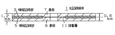
例えば、DVD−5又はDVD−10と呼ばれる光記録媒体1は、図9に示すように、片面に情報記録部3、5の形成された厚さほぼ0.6mmの例えばポリカーボネート樹脂製基板7、9をそれらの情報記録部3、5を内側にして合わせ、接着剤11で接着して一体化したものである。
【0006】
図9において、情報記録部3、5の詳細は省略したが、凹凸パターンをスパイラル状に形成した記録トラックからなる信号記録部や、この信号記録部上に形成された金属製の反射膜を有して形成されている。図9では情報記録部3、5および接着剤層11を誇張して図示しているが、それらは基板7、9の厚み0.6mmに比べて実際は極めて薄くなっている。
【0007】
ところで、DVD−5と呼ばれる光記録媒体1は、情報記録部3、5のうちの片面だけで4.7ギガバイトの情報量を保持できるよう形成され、記録したい情報量が4.7ギガバイトに満たない場合は、片面のみの記憶容量で十分その目的が果たせることになる。
【0008】
そのような場合でも、光記録媒体1は、規格上から全体にわたってその厚さが1.2mmに規定されているため、わざわざ何も信号の入っていない基板7又は9や、必ずしも必要でない信号の入った基板7又は9を貼り付けて構成され、必ずしも必要でない製造工程が必要となって製造工程が煩雑となったり、無駄な材料が消費される欠点があった。
【0009】
そこで本出願人は、既に特許願2000−121561(特開2001−307378号)をもって新規の発明を提案した。
【0010】
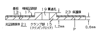
この発明に係る光記録媒体は、図10に示すように、基板13の一方の面を情報記録面とし、その基板13の中央部に読取装置(図示せず。)でその基板13を保持させるための厚さ1.2mmのクランピングエリア(クランプ部)15を有し、このクランプ部15の周囲の情報記録面にスパイラル状又は同心円状のトラックや反射膜(図示せず。)を有する情報記録部17を形成し、そのクランプ部15周囲の厚さをほぼ0.6mmとし、一枚の基板構成とすることによって工程の簡略化や材料の低減を図るとともに、読み取る側の表面からその情報記録部17をほぼ0.6mmの深さに位置させて再生信号の読み取りを確保しようとしたものである。図中符号19はクランプ部15の貫通孔である。
【0011】
このような光記録媒体21は、基板の一方の面に形成した情報記録部17上に紫外線硬化形樹脂からなる保護膜23を形成し、この保護膜23によって上記情報記録部17を形成する反射膜が空気中の酸素によって酸化するのを防止したり、取扱時に反射膜が汚れるのを防止している。
【0012】
なお、図10では保護膜23を誇張して示したが、基板13の厚み0.6mmに比べて実際は極めて薄くなっている。
【0013】
さらに図示はしないが、この保護膜23の上にはこの光記録媒体21の種類や内容を表示するための印刷が施されることが多く、これらの印刷インクにも紫外線硬化形樹脂が使用されることが多い。
【0014】
【特許文献1】
特開2001−307378号公報
【0015】
【発明が解決しようとする課題】
しかしながら、上述したように、厚さ1.2mmのクランプ部15の周囲を厚さ0.6mmとして情報記録部17を形成した一枚基板構成の光記録媒体21は、その情報記録部17上に紫外線硬化形樹脂からなる保護膜23や印刷が施されると、紫外線硬化形樹脂が硬化する際に収縮する性質を有するので、保護膜23や印刷の施された面が内側になるように基板13が変形し易く、その変形が大ききなると正確な情報再生が難しくなる欠点がある。
【0016】
図11AおよびBは、紫外線硬化形樹脂の硬化前後における基板13の形状変化を示したもので、同図中の実線形状は紫外線硬化樹脂の硬化前の基板形状を、同図中の破線形状は紫外線硬化樹脂が塗布され硬化された後の基板形状を模式的に示している。
【0017】
図11AおよびBにおいて、情報記録部17や保護膜23の図示は省略し、基板13の変形状態を右半分だけ強調して図示したが、実際は数ミクロン程度の変形である。
【0018】
一般に、DVDに関する規格では、情報記録部17付近の反りの大きさを±0.8度以下と規定しており、厚さ1.2mmのクランプ部15周囲の基板13の厚さを0.6mmとした光記録媒体21では、その規格を満たさないおそれがあり、改良が望まれていた。
【0019】
また、紫外線硬化樹脂はその硬化後の引っ張り弾性率が大きい場合、基板13を反らせ易く、この観点からも改良が望まれていた。
【0020】
本発明はそのような従来の課題を解決するためになされたもので、紫外線硬化樹脂を保護膜として用いる光記録媒体であっても、光記録媒体の基板の反りを小さく抑え、正確な情報再生や情報記録が可能で、安価、軽量にして耐久性や製造効率が良好な光記録媒体の提供を目的とする。
【0021】
【課題を解決するための手段】
このような課題を解決するために本発明は、合成樹脂基板の中央部にこれをクランプして回転駆動するための厚さ1.2mmのクランプ部を有し、このクランプ部周囲の基板にあってスパイラル状もしくは同心円状の記録トラックを有する情報記録部が一方の面に形成された厚さほぼ0.6mmの光記録媒体において、その情報記録部上に硬化収縮率7.5%以下の紫外線硬化形樹脂の保護膜を形成し構成されている。
【0022】
また、本発明は、合成樹脂基板の中央部にこれをクランプして回転駆動するための厚さ1.2mmのクランプ部を有し、このクランプ部周囲の基板にあってスパイラル状もしくは同心円状の記録トラックを有する情報記録部が一方の面に形成された厚さ0.6mmの光記録媒体において、その情報記録部上に硬化後の引っ張り弾性率が200Mpa以下の紫外線硬化形樹脂の保護膜を形成し構成されている。
【0023】
さらに、本発明では、上記情報記録部上に形成された紫外線硬化形樹脂として、硬化後の引っ張り弾性率が200Mpa以下であって硬化収縮率7.5%以下のものとすることが好ましい。
【0024】
【発明の実施の形態】
以下、本発明に実施の形態を図面を参照して説明する。なお上述した構成と共通する部分には同一の符号を付す。
【0025】
図1および図2は本発明に係る光記録媒体の縦断面図および平面図の一例であり、図1は図2中のI−I間の断面図である。
【0026】
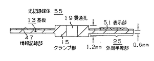
図1および図2において、基板13は、熱可塑性の透明性合成樹脂材料、例えば熱可塑性の透明性ポリカーボネート樹脂から厚さ0.6mmで、直径120mmの円盤状に射出成形されたものである。この製造方法については後述する。
【0027】
基板13の中央部における直径例えば35mmの円形領域は、当該基板13の片面側(図1中上側)に厚さ0.6mm分円盤状に厚く突出して厚さ1.2mmのクランプ部15が形成されており、このクランプ部15の外周はその半分の厚さ0.6mmの外周半厚部25となって一体的に延設されている。
【0028】
すなわち、基板13は、中央の厚さ1.2mmのクランプ部15と、このクランプ部15の外周から延設された厚さ0.6mmの外周半厚部25を有して一体的に形成されている。なお、基板13の中央部すなわちクランプ部15の中央には貫通孔19が形成されている。
【0029】
外周半厚部25において、クランプ部15の一方の端面(図1中下面)とは反対面、すなわちクランプ部15の他方の端面(図1中上面)から厚みにして0.6mmの深さに相当する面には、従来公知の情報記録部17が形成され、本発明の光記録媒体27が構成されている。
【0030】
情報記録部17は、例えば図3(図1中の符号III部分の断面)に示すように、基板13における外周半厚部25に凹凸パターン(ピットおよびランド)をスパイラル状又は同心円状に形成した記録トラックからなる信号記録部29と、この信号記録部29上にアルミニウムなど公知の金属材料を蒸着など公知の手法によって形成した反射膜31とを有して形成されている。
【0031】
反射膜31上には、紫外線硬化樹脂からなる保護膜33が形成されており、この保護膜33を形成する紫外線硬化樹脂は、硬化収縮率7.5%以下のものが使用されるが、硬化後の引っ張り弾性率が200Mpa以下のものであっても良い。
【0032】
図3ではそれら信号記録部29、反射膜31および保護膜33を誇張して図示しているが、実際は外周半厚部25の厚みに比べて極めて薄く、外周半厚部25が0.6mmの厚さになっている。後述する表示部35も同様である。
【0033】
図1〜図3中の符号35は、外周半厚部25にあって情報記録部17の保護膜33上に印刷形成などされた表示部であり、保護膜33と同様に紫外線硬化樹脂からなるインクによって当該光記録媒体27の名称、記録情報の案内、制作者名などが表示されている。
【0034】
すなわち、表示部35を形成する紫外線硬化樹脂も、硬化収縮率7.5%以下のものや、硬化後の引っ張り弾性率が200Mpa以下のものが使用される。
【0035】
そして、光記録媒体27は、従来構成と同様に、図示しない従来公知の再生装置に装填されたとき、再生装置の回転把持部が貫通孔19に一部が差し込まれるとともにそれを挟むようにクランプして回転駆動され、外周半厚部25において図1中下面(矢符P)側から基板13を介して情報記録部17にレーザ光ビームPを照射して記録信号が読み取り再生される。
【0036】
次に、本発明に係る光記録媒体27の製造方法の概略を説明する。
まず、従来公知の手法によって記録信号の格納された金属原盤であるスタンパ37を作る一方、図4に示すように、例えば固定金型としての第1の金型39と可動金型としての第2の金型41を用意する。
【0037】
第1の金型39は、上述したクランプ部15のうち外周半厚部25より突出する部分を形成する凹部43をそのキャビティ内に有するとともに、このキャビティ内へ溶融した熱可塑性ポリカーボネート樹脂を圧入する樹脂注入孔45も有している。なお、スタンパ37は、凹部43を囲むようにリング板状になっている。
【0038】
そして、凹部43を囲むようにスタンパ37を第1の金型39のキャビティ内に配置した後、第2の金型41を第1の金型39に重ねてキャビィ内を密封し、溶融樹脂の金型への射出速度、射出量、加圧力、加圧時間、第1、第2の金型39、41の冷却温度などを適正に制御しながら、射出成形機(図示せず。)から樹脂注入孔45を介して溶融ポリカーボネート樹脂を圧入してスタンパ37を転写し、加圧しながら冷却して第1、第2の金型39、41の型開きを行い、半製品としての光記録媒体27aを取り出す。図4中の符号46は第2の金型41に設けられ貫通孔19を形成する凸部である。
【0039】
その後、所定面にアルミニウムなどの金属材料を蒸着して反射膜31を形成した後、上述した紫外線硬化樹脂からなる保護膜33を形成し、更に、同様な紫外線硬化樹脂からなるインク材料によって表示部35を印刷して上述した光記録媒体27が製造される。なお、貫通孔19は射出成形後の適当な工程で形成される。
【0040】
以下に、本発明者による実験例を示す。
表1は複数の紫外線硬化形樹脂を保護膜33として基板13に塗布し、その前後および経時的な基板反り量を測定したものである。
【0041】
実験に使用する基板13の射出成型条件は以下の通りである。
【0042】
保護膜33を硬化させる紫外線照射条件は下の通りである。
光源 :波長領域 320〜390nmの高圧水銀灯
照射エネルギー:250mJ/cm2
【0043】
弾性率は「レオバイブロンDDV II EA」(製品名)を用いて30℃にて行った。
経時試験の条件は60℃、80%RHの下に96時間の保持である。
【0044】
【表1】
【0045】
なお、紫外線硬化形樹脂名「SK5110」、「ダイキュアクリルSD−2200」、「ダイキュアクリルEX−2513」「ダイキュアクリルEX−2514」はいずれも製品名である。
【0046】
この表1から分かるように、保護膜33を形成する紫外線硬化形樹脂は、紫外線硬化後の硬化収縮率が7.7%以下であるとともに、硬化物の引っ張り弾性率が約300MPa以下である場合に、基板13の反りはDVDの規格である0.8度以下を保つことができることが分かる。
【0047】
本発明においては、保護膜33を形成する紫外線硬化形樹脂は、紫外線硬化後の硬化収縮率が7.7%以下であるか、硬化物の引っ張り弾性率が約300MPa以下のいずれか一方の特性を有しても、本発明の効果達成が可能であるが、双方の特性を有していた方が本発明の効果達成が確実である。
【0048】
次に、保護膜33の硬化後、この上に紫外線硬化形樹脂を主成分とするインクをスクリーン印刷して硬化させ、表示部35を形成する実験例を示す。
【0049】
印刷は基板13の半径23mmから59mmの面積のうち約50%の面積に対して行い、次の紫外線照射条件で行った。
光源 :波長領域300〜390nmのメタルハライドランプ
照射エネルギー:30mJ/cm2
【0050】
印刷されたインクの厚さは約10ミクロンであり、インク硬化後および経時試験後の反りを表2に示す。使用したインクは大日精化工業(株)製の「UV硬化形スクリーン印刷用インキ」SCR−N(黒)である。
【0051】
【表2】
【0052】
この実験結果からも、紫外線硬化後の硬化物の硬化収縮率が7.7%以下であるか、引っ張り弾性率が約300MPa以下である場合に、基板13の反りはDVDの規格である0.8度以下を保つことができることが分かる。
【0053】
表示部35を形成する紫外線硬化形樹脂も、保護膜33と同様に、硬化収縮率が7.7%以下で、引っ張り弾性率が約300MPa以下といった双方の特性を有していた方が、本発明の効果達成が確実である。
【0054】
上述した図1の構成は、クランプ部15の突出部側において、クランプ部15の厚み方向の中央位置に情報記録部17を形成するとともに、基板13を介して光ビームを当てて読み出す構成であったが、本発明はこれに限定されない。
【0055】
例えば、図5に示すように、クランプ部15の突出部側を、上述したような情報記録部47とは反対側に位置させるとともに、この上に保護膜49や表示部51を形成して光記録媒体59を形成し、光ビームをクランプ部の突出部側から当て再生信号を読み出す構成も可能である。
【0056】
また、図6に示すように、厚さ1.2mmのクランプ部15の突出部を厚さ0.6mmの外周半厚部25の両主面側に突出配置し、この外周半厚部25の片面側に情報記録部47、保護膜49および表示部51を形成して光記録媒体55を形成する構成も可能であり、その突出の寸法度合いも適度に按分することが可能であり、外周半厚部25の両主面側に等寸法で突出配置する構成に限定されない。
【0057】
さらにまた、本発明に係る光記録媒体57は、図7に示すように、クランプ部15を基板13と同様に熱可塑性のポリカーボネート樹脂で形成する構成に限らず、クランプ部に相当する面積で厚さ0.6mmの補助層59を基板13の中央部に貼付けて積層し、厚さ1.2mmのクランプ部61を形成する構成も可能である。他の構成は図1と同様であり、情報記録部、保護膜および表示部の図示は省略した。
【0058】
さらに、上述した実施例では、クランプ部15、61の外周は外周半厚部25に直角に接するように例示されているが、クランプ部15、61の外周の形状は特に規定するものではなく、外周半厚部25の情報記録領域の最内周にかけてなだらかに接していても良い。
【0059】
上述した実施の形態は再生専用の光記録媒体27、53、55、57を例にして説明しているが、本発明はこれに限らず記録用の光記録媒体、再生・記録兼用の光記録媒体にも適用できるし、光記録媒体にはいわゆる光磁気記録媒体も含むものである。
【0060】
記録用の光記録媒体としては、例えば、図8に示すように、基板13における外周半厚部25に上述した信号記録部29を形成し、この上に記録変更可能な色素膜などの記録変更部55を形成し、この上に上述した反射膜31や保護膜33を形成して情報記録部57とする構成である。他の構成は上述した図1、図5〜図7と同様である。
【0061】
上述した本発明の実施の形態では、再生専用の光記録媒体27、51、53、55を例にして説明しているが、本発明はこれに限らず記録用の光記録媒体、再生・記録兼用の光記録媒体にも適用できるし、光記録媒体にはいわゆる光磁気記録媒体も含むものである。
【0062】
記録用の光記録媒体としては、例えば、図8に示すように、基板13における外周半厚部25に上述した信号記録部29を形成し、この上に記録変更可能な色素膜などの記録変更部63を形成して情報記録部65を形成し、この上に上述した反射膜31や保護膜33を形成する構成である。他の構成は上述した図1、図5〜図7と同様である。
【0063】
さらに、一回書き込みが可能な光記録媒体の場合には、信号記録部29の上に感光性染料を塗布してアルミニウムなどの金属反射膜を形成すれば良い。
【0064】
【発明の効果】
以上説明したように本発明の光記録媒体は、合成樹脂基板の中央部にこれをクランプして回転駆動するための厚さ1.2mmのクランプ部を有し、このクランプ部周囲の基板を厚さ0.6mmとし、この基板にスパイラル状もしくは同心円状の記録トラックを有する情報記録部を形成し、その情報記録部上に硬化収縮率7.5%以下の紫外線硬化形樹脂の保護膜を形成したから、保護膜の硬化収縮に伴う基板の反りを防ぎ、情報の正確な再生および記録が可能性となる。
また、本発明の光記録媒体は、合成樹脂基板の中央部にこれをクランプして回転駆動するための厚さ1.2mmのクランプ部を有し、このクランプ部周囲の基板を厚さ0.6mmとし、この基板にスパイラル状もしくは同心円状の記録トラックを有する情報記録部を形成し、この情報記録部に硬化後の引っ張り弾性率が200Mpa以下の紫外線硬化形樹脂の保護膜を形成したから、保護膜の引っ張り弾性率を低く保つことにより基板の反りを抑え、情報の正確な再生および記録が可能性となる。
さらに、上記情報記録部上に形成された紫外線硬化形樹脂としては、硬化後の引っ張り弾性率が200Mpa以下であって硬化収縮率7.5%以下のものとする構成では、保護膜の硬化収縮および引っ張り弾性率の観点から基板の反りを確実かつより一層小さく抑え、情報のより正確な再生および記録が可能性となる。なお、本発明の光記録媒体は、従来のDVD用射出成形金型がそのまま使用できる効果を有する。
【図面の簡単な説明】
【図1】本発明に係る光記録媒体の実施の形態を示す断面図(図2中のI−I間断面)である。
【図2】図1に示す光記録媒体の平面図である。
【図3】図1に示す光記録媒体の情報記録部の1例を示す要部断面図である。
【図4】図1に示す光記録媒体の製造工程の1例を説明する断面図である。
【図5】本発明に係る光記録媒体の他の実施の形態を示す断面図である。
【図6】本発明に係る光記録媒体の他の実施の形態を示す断面図である。
【図7】本発明に係る光記録媒体の他の実施の形態を示す断面図である。
【図8】本発明の光記録媒体における情報記録部の他の例を示す要部断面図である。
【図9】従来の一般的な光記録媒体を示す断面図である。
【図10】本発明の参考となる光記録媒体を示す断面図である。
【図11】図10の光記録媒体における形状変化を説明する概略半断面図である。
【符号の説明】
1、21、27、27a、53、55、57 光記録媒体
3、5、17、47、65 情報記録部
7、9、13 基板
11 接着層
15、61 クランプ部(クリンピングエリア)
19 貫通孔
23、33、49 保護膜
25 外周半厚部
29 信号記録部
31 反射膜
33 保護膜
35、51 表示部
37 スタンパ
39 第1の金型
41 第2の金型
43 凹部
45 樹脂注入孔
46 凸部
59 補助層
63 記録変更部[0001]
TECHNICAL FIELD OF THE INVENTION
The present invention relates to an optical recording medium, and is an improvement of an optical recording medium having a recording / holding portion in which a spiral or concentric recording track is formed around a center of a clamp which is clamped to a rotation holding portion of a reproducing apparatus. About.
[0002]
[Prior art]
Among optical recording media for recording music signals, image signals, computer data, computer programs, and the like, for example, a digital versatile disc (hereinafter referred to as a DVD) is a two-layer disc having information recorded on one surface and having a thickness of 0.6 mm. The standard is that the transparent resin substrate is bonded by bonding so that the information recording surfaces are aligned.
[0003]
These substrates are generally made by injection molding, but often do not become completely flat due to residual stress generated by injection molding, and are often warped so that the information recording surface is inside or outside. .
[0004]
However, even if the injection molding machine is different, it is possible to mold substrates warped in the same direction by molding under the same molding conditions, so canceling the warpage by bonding the information recording surfaces together and bonding the substrates As a result, it is possible to obtain a DVD that is almost flat, and if this is loaded into a reading device, accurate information reading is possible.
[0005]
For example, as shown in FIG. 9, an optical recording medium 1 called a DVD-5 or a DVD-10 has an information recording portion 3 or 5 formed on one side and a substrate 7 made of, for example, a polycarbonate resin having a thickness of approximately 0.6 mm. 9 are assembled together with their information recording portions 3 and 5 inside, and bonded together with an adhesive 11.
[0006]
In FIG. 9, although details of the information recording sections 3 and 5 are omitted, a signal recording section including a recording track in which a concavo-convex pattern is formed in a spiral shape, and a metal reflection film formed on the signal recording section are provided. It is formed. Although the information recording portions 3 and 5 and the adhesive layer 11 are exaggerated in FIG. 9, they are actually extremely thin compared to the thickness of the substrates 7 and 9 of 0.6 mm.
[0007]
Meanwhile, the optical recording medium 1 called DVD-5 is formed so that only one side of the information recording units 3 and 5 can hold an information amount of 4.7 gigabytes, and the information amount to be recorded is less than 4.7 gigabytes. If not, the storage capacity of only one side will suffice for that purpose.
[0008]
Even in such a case, since the thickness of the optical recording medium 1 is specified to be 1.2 mm throughout from the standard, the substrate 7 or 9 in which no signal is included or the signal of an unnecessary signal is not required. It is configured by attaching the substrate 7 or 9 containing it, and there is a disadvantage that a manufacturing process that is not always necessary is required, so that the manufacturing process becomes complicated and wasteful materials are consumed.
[0009]
Therefore, the present applicant has already proposed a new invention based on Patent Application 2000-121561 (Japanese Patent Application Laid-Open No. 2001-307378).
[0010]
In the optical recording medium according to the present invention, as shown in FIG. 10, one surface of the substrate 13 is used as an information recording surface, and the substrate 13 is held by a reader (not shown) at the center of the substrate 13. Having a 1.2 mm-thick clamping area (clamp portion) 15 for recording, and information having a spiral or concentric track or a reflection film (not shown) on an information recording surface around the clamp portion 15. The recording portion 17 is formed, the thickness around the clamp portion 15 is set to approximately 0.6 mm, and a single substrate structure is used to simplify the process and reduce the material, and to read the information from the surface on the reading side. The recording section 17 is positioned at a depth of about 0.6 mm to secure reading of a reproduced signal. Reference numeral 19 in the figure is a through hole of the clamp portion 15.
[0011]
In such an optical recording medium 21, a protective film 23 made of an ultraviolet curable resin is formed on an information recording portion 17 formed on one surface of a substrate, and the protective film 23 forms the information recording portion 17 by reflection. The film is prevented from being oxidized by oxygen in the air, and the reflection film is prevented from being stained during handling.
[0012]
Although the protective film 23 is exaggerated in FIG. 10, it is actually extremely thin compared to the thickness of the substrate 13 of 0.6 mm.
[0013]
Further, although not shown, printing for displaying the type and content of the optical recording medium 21 is often performed on the protective film 23, and ultraviolet curable resin is also used for these printing inks. Often.
[0014]
[Patent Document 1]
JP 2001-307378 A
[Problems to be solved by the invention]
However, as described above, the single-substrate optical recording medium 21 in which the information recording section 17 is formed with the thickness of the periphery of the clamp section 15 having a thickness of 1.2 mm being 0.6 mm is placed on the information recording section 17. When the protective film 23 made of an ultraviolet-curable resin is printed, since the ultraviolet-curable resin has a property of shrinking when it is cured, the substrate is placed such that the surface on which the protective film 23 or the printed surface is inward. 13 is easily deformed, and if the deformation is large, accurate information reproduction becomes difficult.
[0016]
11A and 11B show the shape change of the substrate 13 before and after curing of the ultraviolet curable resin. The solid line in FIG. 11A shows the substrate shape before curing of the ultraviolet curable resin, and the broken line in FIG. FIG. 3 schematically shows a substrate shape after an ultraviolet curable resin is applied and cured.
[0017]
11A and 11B, the illustration of the information recording section 17 and the protective film 23 is omitted, and the deformed state of the substrate 13 is illustrated with only the right half emphasized. However, the deformed state is actually several microns.
[0018]
In general, in the DVD standard, the size of the warp near the information recording section 17 is specified to be ± 0.8 degrees or less, and the thickness of the substrate 13 around the clamp section 15 having a thickness of 1.2 mm is set to 0.6 mm. The optical recording medium 21 may not satisfy the standard, and improvement has been desired.
[0019]
In addition, when the ultraviolet curable resin has a large tensile elasticity after curing, the substrate 13 is easily warped, and an improvement has been desired from this viewpoint.
[0020]
The present invention has been made to solve such a conventional problem. Even in an optical recording medium using an ultraviolet curable resin as a protective film, warpage of the substrate of the optical recording medium is suppressed to be small, and accurate information reproduction is performed. It is an object of the present invention to provide an optical recording medium capable of recording information at a low cost, light weight, and excellent in durability and production efficiency.
[0021]
[Means for Solving the Problems]
In order to solve such a problem, the present invention has a clamp portion having a thickness of 1.2 mm for clamping and rotating the synthetic resin substrate at a central portion thereof, and a substrate around the clamp portion is provided. When an information recording portion having a spiral or concentric recording track is formed on one surface of an optical recording medium having a thickness of approximately 0.6 mm, ultraviolet rays having a curing shrinkage of 7.5% or less are formed on the information recording portion. A protective film of a curable resin is formed.
[0022]
Further, the present invention has a clamp portion having a thickness of 1.2 mm for clamping and rotating the synthetic resin substrate at a central portion thereof, and the substrate around the clamp portion has a spiral or concentric shape. In an optical recording medium having a thickness of 0.6 mm in which an information recording portion having a recording track is formed on one surface, a protective film of an ultraviolet curable resin having a tensile elastic modulus after curing of 200 Mpa or less is formed on the information recording portion. Formed and configured.
[0023]
Further, in the present invention, it is preferable that the ultraviolet curable resin formed on the information recording section has a tensile elastic modulus after curing of 200 Mpa or less and a curing shrinkage rate of 7.5% or less.
[0024]
BEST MODE FOR CARRYING OUT THE INVENTION
Hereinafter, embodiments of the present invention will be described with reference to the drawings. Note that the same reference numerals are given to portions common to the above-described configuration.
[0025]
1 and 2 are an example of a longitudinal sectional view and a plan view of an optical recording medium according to the present invention, and FIG. 1 is a sectional view taken along line II in FIG.
[0026]
1 and 2, a substrate 13 is injection-molded into a disc having a thickness of 0.6 mm and a diameter of 120 mm from a thermoplastic transparent synthetic resin material, for example, a thermoplastic transparent polycarbonate resin. This manufacturing method will be described later.
[0027]
A circular region having a diameter of, for example, 35 mm in the central portion of the substrate 13 protrudes from one side of the substrate 13 (upper side in FIG. 1) in a disk-like manner by a thickness of 0.6 mm to form a clamp portion 15 having a thickness of 1.2 mm. The outer circumference of the clamp portion 15 is formed as a half-thick outer peripheral portion 25 having a thickness of 0.6 mm, and is integrally extended therefrom.
[0028]
That is, the substrate 13 is integrally formed with the central clamp portion 15 having a thickness of 1.2 mm and the outer peripheral half-thick portion 25 having a thickness of 0.6 mm extending from the outer periphery of the clamp portion 15. ing. A through hole 19 is formed at the center of the substrate 13, that is, at the center of the clamp 15.
[0029]
In the outer peripheral half-thickness portion 25, the surface is opposite to one end surface (the lower surface in FIG. 1) of the clamp portion 15, that is, from the other end surface (the upper surface in FIG. 1) of the clamp portion 15 to a depth of 0.6 mm in thickness. A conventionally known information recording unit 17 is formed on the corresponding surface, and the optical recording medium 27 of the present invention is configured.
[0030]
The information recording unit 17 has, for example, a concavo-convex pattern (pits and lands) formed in a spiral shape or concentric shape on the outer peripheral half-thick portion 25 of the substrate 13 as shown in FIG. A signal recording section 29 composed of a recording track and a reflective film 31 formed on the signal recording section 29 by a known method such as vapor deposition of a known metal material such as aluminum are formed.
[0031]
A protective film 33 made of an ultraviolet curable resin is formed on the reflective film 31. The ultraviolet curable resin forming the protective film 33 has a curing shrinkage of 7.5% or less. The subsequent tensile modulus may be 200 Mpa or less.
[0032]
3, the signal recording portion 29, the reflective film 31, and the protective film 33 are exaggeratedly shown. However, in actuality, the thickness of the outer peripheral half-thick portion 25 is extremely thin compared to the thickness of the outer peripheral half-thick portion 25. It is thick. The same applies to a display unit 35 described later.
[0033]
Reference numeral 35 in FIGS. 1 to 3 denotes a display portion which is formed by printing on the protective film 33 of the information recording portion 17 in the outer peripheral half-thick portion 25 and is made of an ultraviolet curable resin like the protective film 33. The name of the optical recording medium 27, guidance of recording information, the name of a creator, and the like are displayed by ink.
[0034]
That is, as the ultraviolet curable resin forming the display section 35, a resin having a curing shrinkage of 7.5% or less and a resin having a tensile elasticity of 200 Mpa or less after curing are used.
[0035]
Then, similarly to the conventional configuration, when the optical recording medium 27 is loaded into a conventionally known reproducing device (not shown), the rotating grip portion of the reproducing device is partially inserted into the through hole 19 and clamped so as to sandwich it. The information recording unit 17 is irradiated with the laser beam P from the lower surface (arrow P) in FIG.
[0036]
Next, an outline of a method for manufacturing the optical recording medium 27 according to the present invention will be described.
First, a stamper 37, which is a metal master in which a recording signal is stored, is manufactured by a conventionally known method, and, as shown in FIG. 4, for example, a first die 39 as a fixed die and a second die 39 as a movable die. Is prepared.
[0037]
The first mold 39 has a concave portion 43 which forms a portion of the above-described clamp portion 15 projecting from the outer peripheral half-thickness portion 25 in its cavity, and press-fits a molten thermoplastic polycarbonate resin into this cavity. It also has a resin injection hole 45. Note that the stamper 37 has a ring plate shape so as to surround the recess 43.
[0038]
Then, after the stamper 37 is arranged in the cavity of the first mold 39 so as to surround the concave portion 43, the second mold 41 is overlapped with the first mold 39 to seal the inside of the cab and to seal the molten resin. While appropriately controlling the injection speed, injection amount, pressing force, pressurizing time, and cooling temperature of the first and second molds 39 and 41 into the mold, a resin is injected from an injection molding machine (not shown). The stamper 37 is transferred by press-fitting the molten polycarbonate resin through the injection hole 45, and cooled while being pressurized to open the first and second molds 39 and 41, thereby forming the optical recording medium 27a as a semi-finished product. Take out. Reference numeral 46 in FIG. 4 denotes a projection provided on the second mold 41 to form the through hole 19.
[0039]
After that, a reflective film 31 is formed by evaporating a metal material such as aluminum on a predetermined surface, and then a protective film 33 made of the above-described ultraviolet curable resin is formed. The above-described optical recording medium 27 is manufactured by printing 35. The through holes 19 are formed in an appropriate step after injection molding.
[0040]
The following is an experimental example by the present inventors.
Table 1 shows the results obtained by applying a plurality of ultraviolet curable resins to the substrate 13 as the protective film 33, and measuring the amount of substrate warpage before and after and over time.
[0041]
The injection molding conditions for the substrate 13 used in the experiment are as follows.
[0042]
The ultraviolet irradiation conditions for curing the protective film 33 are as follows.
Light source: wavelength range 320 to 390 nm high pressure mercury lamp Irradiation energy: 250 mJ / cm2
[0043]
The elastic modulus was measured at 30 ° C. using “Reo Vibron DDV II EA” (product name).
The conditions of the aging test are holding at 60 ° C. and 80% RH for 96 hours.
[0044]
[Table 1]
[0045]
The UV-curable resin names “SK5110”, “Dicy Acrylic SD-2200”, “Dycure Acrylic EX-2513”, and “Dycure Acrylic EX-2514” are all product names.
[0046]
As can be seen from Table 1, the UV curable resin forming the protective film 33 has a curing shrinkage of 7.7% or less after UV curing and a tensile elasticity of the cured product of about 300 MPa or less. Further, it can be seen that the warpage of the substrate 13 can be maintained at 0.8 degrees or less, which is the DVD standard.
[0047]
In the present invention, the UV-curable resin forming the protective film 33 has a property that either the curing shrinkage after UV curing is 7.7% or less or the tensile modulus of the cured product is about 300 MPa or less. Although the effect of the present invention can be achieved even if the above is included, the effect of the present invention is more reliably achieved by having both characteristics.
[0048]
Next, an experimental example will be described in which after the protective film 33 is cured, an ink containing a UV-curable resin as a main component is screen-printed and cured thereon to form the display section 35.
[0049]
Printing was performed on about 50% of the area of the substrate 13 with a radius of 23 mm to 59 mm under the following ultraviolet irradiation conditions.
Light source: Metal halide lamp with a wavelength range of 300 to 390 nm Irradiation energy: 30 mJ / cm2
[0050]
The thickness of the printed ink is about 10 microns, and the warpage after curing of the ink and after the aging test is shown in Table 2. The ink used was "UV curable screen printing ink" SCR-N (black) manufactured by Dainichi Seika Industry Co., Ltd.
[0051]
[Table 2]
[0052]
From this experimental result, it is understood that the warpage of the substrate 13 is DVD standard when the curing shrinkage of the cured product after ultraviolet curing is 7.7% or less or the tensile elasticity is about 300 MPa or less. It can be seen that 8 degrees or less can be maintained.
[0053]
Like the protective film 33, the ultraviolet curable resin forming the display unit 35 also has both characteristics such as a curing shrinkage of 7.7% or less and a tensile elasticity of about 300 MPa or less. The effects of the invention are surely achieved.
[0054]
The above-described configuration of FIG. 1 has a configuration in which the information recording unit 17 is formed at the center of the clamp unit 15 in the thickness direction on the protruding portion side of the clamp unit 15 and is read out by applying a light beam via the substrate 13. However, the present invention is not limited to this.
[0055]
For example, as shown in FIG. 5, the projecting portion side of the clamp portion 15 is located on the opposite side to the information recording portion 47 as described above, and a protective film 49 and a display portion 51 are formed thereon to form a light source. A configuration is also possible in which the recording medium 59 is formed, and a reproduction signal is read out by applying a light beam from the protruding portion side of the clamp portion.
[0056]
As shown in FIG. 6, the protrusions of the clamp portion 15 having a thickness of 1.2 mm are disposed on both main surfaces of the half-thick outer peripheral portion 25 having a thickness of 0.6 mm. It is also possible to form an optical recording medium 55 by forming the information recording section 47, the protective film 49 and the display section 51 on one side, and it is also possible to appropriately divide the degree of protrusion of the optical recording medium 55. The present invention is not limited to the configuration in which the thick portions 25 are arranged so as to protrude with equal dimensions on both main surfaces.
[0057]
Further, as shown in FIG. 7, the optical recording medium 57 according to the present invention is not limited to the configuration in which the clamp portion 15 is formed of a thermoplastic polycarbonate resin like the substrate 13, and has a thickness corresponding to the area corresponding to the clamp portion. A configuration is also possible in which an auxiliary layer 59 having a thickness of 0.6 mm is attached to the central portion of the substrate 13 and laminated to form a clamp portion 61 having a thickness of 1.2 mm. Other configurations are the same as those in FIG. 1, and the illustration of the information recording unit, the protective film, and the display unit is omitted.
[0058]
Further, in the above-described embodiment, the outer circumferences of the clamp portions 15 and 61 are illustrated as being in contact with the outer peripheral half-thickness portion 25 at right angles. However, the outer shapes of the clamp portions 15 and 61 are not particularly defined. It may be gently in contact with the innermost circumference of the information recording area of the outer half-thickness section 25.
[0059]
Although the above-described embodiments have been described by taking the read-only optical recording media 27, 53, 55, and 57 as examples, the present invention is not limited to this, and the present invention is not limited to this. The present invention can be applied to a medium, and an optical recording medium includes a so-called magneto-optical recording medium.
[0060]
As an optical recording medium for recording, for example, as shown in FIG. 8, the above-mentioned signal recording portion 29 is formed on the outer peripheral half-thick portion 25 of the substrate 13, and the recording change such as a recordable dye film is performed thereon. An information recording portion 57 is formed by forming a portion 55 and forming the above-described reflective film 31 and protective film 33 thereon. Other configurations are the same as those in FIGS. 1 and 5 to 7 described above.
[0061]
In the embodiments of the present invention described above, the read-only optical recording media 27, 51, 53, and 55 have been described as examples. However, the present invention is not limited to this, and the recording optical recording medium, the read / write The present invention can be applied to a dual-purpose optical recording medium, and the optical recording medium includes a so-called magneto-optical recording medium.
[0062]
As an optical recording medium for recording, for example, as shown in FIG. 8, the above-mentioned signal recording portion 29 is formed on the outer peripheral half-thick portion 25 of the substrate 13, and the recording change such as a recordable dye film is performed thereon. In this configuration, the information recording section 65 is formed by forming the section 63, and the above-described reflective film 31 and protective film 33 are formed thereon. Other configurations are the same as those in FIGS. 1 and 5 to 7 described above.
[0063]
Further, in the case of an optical recording medium that can be written once, a photosensitive dye may be applied on the signal recording section 29 to form a metal reflection film such as aluminum.
[0064]
【The invention's effect】
As described above, the optical recording medium of the present invention has a 1.2 mm-thick clamp portion for clamping and rotating the synthetic resin substrate at the center portion thereof. An information recording portion having a spiral or concentric recording track is formed on the substrate, and a protective film of an ultraviolet curable resin having a curing shrinkage of 7.5% or less is formed on the information recording portion. Therefore, warpage of the substrate due to curing shrinkage of the protective film is prevented, and accurate reproduction and recording of information becomes possible.
Further, the optical recording medium of the present invention has a clamp portion having a thickness of 1.2 mm for clamping and rotating the synthetic resin substrate at a central portion thereof. 6 mm, an information recording portion having a spiral or concentric recording track was formed on this substrate, and a protective film of an ultraviolet curable resin having a tensile elastic modulus after curing of 200 Mpa or less was formed on the information recording portion. By keeping the tensile modulus of the protective film low, the warpage of the substrate is suppressed, and accurate reproduction and recording of information becomes possible.
Further, the ultraviolet curable resin formed on the information recording section may have a tensile elasticity of 200 Mpa or less after curing and a curing shrinkage of 7.5% or less. In addition, from the viewpoint of the tensile elasticity, the warpage of the substrate is surely and further reduced, and more accurate reproduction and recording of information becomes possible. The optical recording medium of the present invention has an effect that a conventional injection molding die for DVD can be used as it is.
[Brief description of the drawings]
FIG. 1 is a cross-sectional view (cross-section taken along II in FIG. 2) showing an embodiment of an optical recording medium according to the present invention.
FIG. 2 is a plan view of the optical recording medium shown in FIG.
FIG. 3 is a sectional view of a main part showing an example of an information recording section of the optical recording medium shown in FIG.
FIG. 4 is a cross-sectional view illustrating one example of a manufacturing process of the optical recording medium shown in FIG.
FIG. 5 is a cross-sectional view showing another embodiment of the optical recording medium according to the present invention.
FIG. 6 is a cross-sectional view showing another embodiment of the optical recording medium according to the present invention.
FIG. 7 is a sectional view showing another embodiment of the optical recording medium according to the present invention.
FIG. 8 is a sectional view of a main part showing another example of the information recording section in the optical recording medium of the present invention.
FIG. 9 is a sectional view showing a conventional general optical recording medium.
FIG. 10 is a cross-sectional view showing an optical recording medium serving as a reference of the present invention.
11 is a schematic half-sectional view illustrating a shape change in the optical recording medium of FIG.
[Explanation of symbols]
1, 21, 27, 27a, 53, 55, 57 Optical recording media 3, 5, 17, 47, 65 Information recording sections 7, 9, 13 Substrate 11 Adhesive layers 15, 61 Clamp section (crimping area)
19 Through-holes 23, 33, 49 Protective film 25 Peripheral half-thickness portion 29 Signal recording unit 31 Reflective film 33 Protective film 35, 51 Display unit 37 Stamper 39 First mold 41 Second mold 43 Concave part 45 Resin injection hole 46 convex portion 59 auxiliary layer 63 recording change portion