JP2004177277A - Tackiness testing device for prepreg and tackiness test method of prepreg - Google Patents
Tackiness testing device for prepreg and tackiness test method of prepreg Download PDFInfo
- Publication number
- JP2004177277A JP2004177277A JP2002344035A JP2002344035A JP2004177277A JP 2004177277 A JP2004177277 A JP 2004177277A JP 2002344035 A JP2002344035 A JP 2002344035A JP 2002344035 A JP2002344035 A JP 2002344035A JP 2004177277 A JP2004177277 A JP 2004177277A
- Authority
- JP
- Japan
- Prior art keywords
- prepreg
- pedestal
- test
- prepreg tape
- test piece
- Prior art date
- Legal status (The legal status is an assumption and is not a legal conclusion. Google has not performed a legal analysis and makes no representation as to the accuracy of the status listed.)
- Withdrawn
Links
Images


Abstract
Description
【0001】
【発明の属する技術分野】
本発明は、繊維強化プラスチックの成型物を製造する際に使用されるシート状のプリプレグ表面の粘着性を試験する装置に関する。
【0002】
【従来の技術】
航空機等の構造部材には、軽量で機械的特性に優れる繊維強化プラスチックが使用されることがある。
繊維強化プラスチックからこれら成型物を製造する際には、まず、繊維強化プラスチックの前駆体であるプリプレグを金型内に敷き、必要に応じて所定の層数をその上に積層し、ついでこれを加熱して樹脂を硬化させ、冷却、脱型する方法が多く用いられている。
プリプレグとしては、例えば、炭素繊維、ガラス繊維などの繊維からなる織物や編物に樹脂又は樹脂の溶液が含浸したものや、一方向に引き揃えられた多数本の繊維に樹脂又は樹脂の溶液が含浸したものなどがあるが、上述したような航空機等の用途には、例えば、300本程度の炭素繊維束にエポキシ樹脂が含浸率35質量%程度で含浸され、幅(炭素繊維束に対して垂直方向の長さ)150mm前後、厚み0.2mm前後とされたテープ状のものが使用されることがよくある。このようなプリプレグテープは、含浸している樹脂が、通常粘着性を有しているため、片面に離型紙を備えた状態で巻回され、巻物となっている。
【0003】
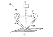
このような巻物からプリプレグテープを引き出し、連続的に金型内に敷き、さらに積層する装置として、図7に示すような貼り付け機構部60を備えた自動積層装置がある(特許文献1参照)。
この例の貼り付け機構部60は、巻物からプリプレグテープ61を連続的に供給する材料供給リール62と、プリプレグテープ61を金型の表面上の所定位置に押さえつけ、プリプレグテープ61に含浸している樹脂の粘着性を利用して金型あるいは金型上にすでに積層されたプリプレグテープに貼り付ける押さえ貼りローラ63と、貼り付けられたプリプレグテープ61から離型紙64を巻き取る巻き取りロール65と、プリプレグテープ61を所定の箇所で切断する図示略の切断手段とが、1つの図示略の架台に取り付けられている。そして、この貼り付け機構部60はさらに自動制御部66を備えていて、あらかじめ入力された座標データにそって架台ごと移動して、プリプレグテープ61を連続的に所定位置に貼り付けたり、切断したり、積層したりできるようになっている。
【0004】
【特許文献1】
特開平5−254724号公報
【0005】
【発明が解決しようとする課題】
ところが、このような貼り付け機構部においては、プリプレグテープに含浸している樹脂が備える粘着性を利用して、このプリプレグテープを金型あるいは金型上にすでに積層されたプリプレグテープに貼り付けているので、含浸している樹脂の種類によっては、粘着性が不十分で、貼り付け時にプリプレグテープが滑ってしまうことがあった。プリプレグテープが滑ってしまうと、入力された座標データどおり正確に貼り付けることができず、その結果、所望の物性の成型物が得られないという問題があった。
一方、プリプレグテープに含浸した樹脂の粘着性が大きすぎると、プリプレグテープが滑らなくはなるものの、プリプレグテープを貼り付けたり積層したりしている間に、プリプレグテープに異物が付着するなどして、この工程をやり直す必要が生じた場合などに、容易にプリプレグテープを剥がすことができないという問題が生じる。
【0006】
そのため、図7に示したような貼り付け機構部を備えた自動積層装置でプリプレグテープを貼り付ける際には、十分に粘着して滑らず、しかも、剥がす必要が有る場合には容易に剥がせるような適度な粘着性を備えたプリプレグテープが要求されている。
【0007】
しかしながら、プリプレグテープをこのような自動積層装置を使用して実際に金型上またはすでに積層されたプリプレグテープに貼り付け、積層する前の段階で、そのプリプレグテープが滑らず、かつ、金型あるいはすでに金型上に積層されたプリプレグテープから容易に剥がせるものであるかどうかを正確に判断する試験装置や試験方法は知られておらず、文献にも開示はない。
そのため、従来は、プリプレグテープの製造現場の作業者がそのタック感などから官能的に判断せざるを得なかった。ところが、このような方法では作業者によって判断基準にばらつきが生じるなどして、使用可能と判断されたプリプレグテープであっても、実際に自動積層装置に供した場合には滑ったり、過度に粘着したりして、使用できないことがあった。すなわち、従来プリプレグテープが自動積層装置で使用可能かどうかは、実際に自動積層装置で使用してみて初めて判断できる場合がほとんどであった。
【0008】
また、このような自動積層装置は非常に高価であるため、プリプレグテープの製造現場や設計現場が、プリプレグテープが自動積層装置で使用可能かどうかを判断する目的でこれを所有することは、コスト面などから困難であった。そのため、プリプレグテープの製造現場や設計現場においては、どのような組成の樹脂を含浸させたプリプレグテープが自動積層装置での使用に適しているか、また、どのような条件下で貼り付け工程を行うことが適しているか、などについてデータ収集することも難しかった。
【0009】
本発明は上記事情に鑑みてなされたもので、プリプレグテープのようなシート状のプリプレグの表面が適度な粘着性を有していて、自動積層装置で金型上あるいは金型上に積層されたプリプレグテープに貼り付ける際に、滑らず、かつ、容易に剥がせるものであるかどうかを、簡便でかつ実際の貼り付け、積層工程に近い条件下で試験できる試験装置および試験方法を提供することを課題とする。
【0010】
【課題を解決するための手段】
本発明のプリプレグの粘着性試験装置は、シート状のプリプレグが載置される台座と、載置された前記プリプレグに対して垂直に圧接する圧子と、前記プリプレグと台座とが接触したまま互いに相対移動した際に、該相対移動の開始に要する荷重を測定する荷重測定手段とを具備することを特徴とする。
前記プリプレグを固定する固定手段を備え、前記荷重測定手段は、前記台座を引張って該台座が移動を開始する際の引張り荷重を測定することが好ましい。
または、前記台座を固定する固定手段を備え、前記荷重測定手段は、前記プリプレグを引張って該プリプレグが移動を開始する際の引張り荷重を測定してもよい。この際前記圧子は、前記圧接したままプリプレグに同伴して移動してもよい。
前記台座における前記プリプレグとの接触面は、離型加工されていてもよい。
本発明のプリプレグの粘着性試験方法は、シート状のプリプレグを台座に載置し、載置された前記プリプレグに対して圧子を垂直に圧接した状態で前記プリプレグと前記台座とを接触させたまま互いに相対移動させ、該相対移動の開始に要する荷重を測定することを特徴とする。
本発明の他のプリプレグの粘着性試験方法は、シート状の第1のプリプレグを台座に固着し、固着された前記第1のプリプレグにシート状の第2のプリプレグを載置し、載置された前記第2のプリプレグに対して圧子を垂直に圧接した状態で、前記第1のプリプレグと前記第2のプリプレグとを接触させたまま互いに相対移動させ、該相対移動の開始に要する荷重を測定することを特徴とする。
【0011】
【発明の実施の形態】
本発明の粘着性試験装置(以下、試験装置という。)は、プリプレグテープなどのシート状に形成されたプリプレグが、従来の技術において図7を示して説明したような貼り付け機構部60を備えた自動積層装置での使用に適しているかどうか、その粘着性を試験するものである。
以下、実施形態例を例示して、本発明の試験装置について詳細に説明する。
【0012】
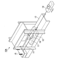
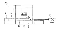
図1および2は、第1の実施形態例の試験装置10Aの所定位置に、試験対象であるプリプレグテープ試験片(以下、試験片という。)11を配した状態を示す斜視図および正面図である。
この例で試験される試験片11は、航空機等の構造部材に使用されるプリプレグテープを試験用に切り出したものであって、プリプレグテープの長さ方向に沿って略平行に引き揃えられた複数本の炭素繊維に、エポキシ樹脂が含浸したプリプレグ層と、このプリプレグ層の片面に設けられた離型紙などの離型シートとからなるものである。
【0013】
図示の試験装置10Aは、水平に配置された平板状の台座12を有していて、台座の上面上に試験片11が、離型シート側が上側となるように載置されている。また、この例の台座12は、その下面に図示略のスラストベアリングが設けられていて、載置された試験片11の長さ方向(図2中左右方向)に沿って基台13上を移動できるようになっている。さらにこの例では、台座12における移動方向の一方の端部には、荷重測定手段としてフォースゲージ14が接続され、試験片11における他方側の端部が固定手段であるクランプ15によって基台13上に固定されている。よって、このフォースゲージ14を、図1および図2中矢印方向に引張ることにより、試験片11と台座12とは接したまま台座12のみが移動し、移動の開始に要する引張り荷重をフォースゲージ14で測定できるようになっている。
【0014】
なお、この例においては、台座12の上面上に四フッ化エチレンなどのフッ素系樹脂からなる離型シート16が貼着されて台座12の上面が離型加工され、その上に試験片11が載置されている。よって、離型シート16と試験片11のプリプレグ層とが接触した状態となっている。これは、図7のような貼り付け機構部60を備えた自動積層装置を使用して、実際に金型上にプリプレグテープを貼り付けていく際には、後の脱型工程において硬化後の成型物が容易に金型から抜けるように、あらかじめ金型上に四フッ化エチレンなどのフッ素系樹脂からなる離型シートを敷き、これの上にプリプレグシートを貼り付けていく場合があるためであって、このような場合を想定し、できるだけ実際に近い条件下で試験片11を試験するために、この試験装置10Aにおいても台座12上に離型シート16を配置している。
また、離型加工の方法としては、このように台座12における試験片11との接触面(上面)に離型シート16を設ける方法の他、この接触面に離型剤を塗布しておく方法などであってもよい。また、離型加工は台座12の上面上において、少なくとも後述する圧子に対応する部分になされていればよい。
【0015】
この例の試験装置10Aは、台座12に載置された試験片11に対して垂直に圧接する円柱形の圧子17を有している。
この圧子17には図示略のエアシリンダが接続されていて、エアシリンダに供給する空気圧を調整することによって、試験片11の上面に対して垂直方向(図中上下方向)に移動して、試験片11に対して所望の圧力で圧接したり、試験片11から離れたりするようになっている。また、この例の試験装置10Aは、試験対象のプリプレグテープが、図7に示すような貼り付け機構部60を備えた自動積層装置での使用に適した粘着性を備えているかどうかを試験するものであるので、具備している圧子17は、図7に示された貼り付けローラ63を模擬し、直径約20mm、厚み約40mmの鉄製の円柱形とされ、その周面が試験片11に圧接するようになっている。なお、ここで圧子17は、回動可能なローラであってもよい。
【0016】
次にこの例の試験装置10Aで試験片11を試験する方法について説明する。
まず、離型シート16が貼着された台座12の上面と、プリプレグ層側が接するように試験片11を載置する。ついで、台座12における移動方向の一方の端部にフォースゲージ14を接続し、試験片11における他方側の端部をクランプ15で挟んで固定する。
ついで、図示略のエアシリンダを作動させ、圧子17を試験片11に対して図3に示すように垂直に圧接させる。圧接させる圧力は、自動積層装置で実際にプリプレグテープを金型上に貼り付ける際に加えられる圧力と同等とするなど、適宜設定すればよく、この例では20Nとしている。
ついで、圧子17を圧接させた状態のまま、台座12に接続されたフォースゲージ14を、矢印方向、すなわち炭素繊維の長さ方向に引張る。すると、フォースゲージ14が指示する引張り荷重がある値となった時点で、台座12上の離型シート16と試験片11との間において滑りが生じ、台座12が基台13上を移動し始める。このときの台座12が移動を開始した際の引張り荷重を測定値として読みとる。
【0017】
ここであらかじめ、このような試験を行った際の測定値がどのような範囲にある試験片11であると、図7のような貼り付け機構部60を備えた自動積層装置で実際に金型に貼り付けていく際に金型上を滑らず、しかも金型から容易に剥がせるか、相関関係を把握しておく。すると、新たに試作されたプリプレグテープから試験片11を切り出し、それについて上述のように同様に試験をするだけで、そのプリプレグテープが自動積層装置での使用に適したものであるかどうかを事前に判断することができる。測定値が特定の範囲未満であると、粘着性が不十分で金型上で滑ってしまう可能性が大きく、特定の範囲を超えると、粘着性が大きすぎて金型から容易には剥がれない可能性が大きい。この例の場合には、測定値が40〜50Nの範囲であると、そのプリプレグテープは、自動積層装置での使用に適している。
【0018】
また、このような試験装置10Aを使用すると、プリプレグテープが自動積層装置で使用可能かどうか判断できるだけでなく、プリプレグ層に使用した樹脂の組成と粘着性との相関関係を求めることができるので、プリプレグテープに使用する樹脂の設計指針を得ることも可能となる。また、温度を変化させるなど種々の条件下で試験を行うことにより、実際に自動積層装置でプリプレグテープを金型上に貼り付けていく際の最適条件を求めることもでき、プリプレグテープの製造、設計が効率化する。
【0019】
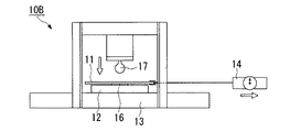
次に第2の実施形態例について説明する。
図4はこの例の試験装置10Bの正面図であって、この試験装置10Bにおいては、台座12ではなく試験片11を引張って試験片11が移動を開始した際の引張り荷重を測定する点で図1の試験装置10Aと異なる。よって、この例の試験装置10Bにおいては、台座12はスラストベアリングを具備せず、基台13上に固定され、フォースゲージ14は台座ではなく、試験片11の端部に接続されている。
この例の試験装置10Bを使用して試験する場合には、図1の試験装置10Aの場合と同様に、離型シート16が貼着された台座12の上面と、プリプレグ層側が接するように試験片11を載置し、ついで、試験片11における移動方向の一方の端部にフォースゲージ14を接続する。その後、図示略のエアシリンダを作動させ、圧子17を試験片11に対して垂直に圧接させ、その状態のまま、試験片11に接続されたフォースゲージ14を矢印方向に引張る。そして、試験片11が台座12上を滑って移動し始めた際のフォースゲージ14が指示する引張り荷重を測定する。
【0020】
このように第2の実施形態例の試験装置10Bを使用した場合にも、あらかじめ、試験片11が台座12上を滑って移動し始める際の引張り荷重の測定値と、自動積層装置での使用の適否との相関関係を求めておき、そのうえで試作されたプリプレグテープなどを試験することによって、そのプリプレグテープが自動積層装置の使用に適した粘着性を備えているかどうか判断することができる。また、第1の実施形態例の試験装置10Aの場合と同様に、プリプレグテープに使用する樹脂の設計指針を得たり、自動積層装置でプリプレグテープを金型上に貼り付けていく際の最適条件を求めたりすることもできる。
【0021】
以上説明したように第1および第2の実施形態例の試験装置10A,10Bを使用することにより、従来、実際に自動積層装置で使用するまでは判断が困難であったプリプレグテープの粘着性を簡単な装置で容易に試験できるが、図7に示した貼り付け機構部60での使用の適否をより正確に判断するためには、図5に示す試験装置10Cを使用してもよい。
【0022】
図5に示す第3の実施形態例の試験装置10Cは、第2の実施形態例の試験装置10Bの場合と同様に、台座12が基台13に固定され、固定された台座12上において試験片11を移動させ、その際の引張り荷重を測定するものであるが、この例の試験装置においては、圧子17が試験片11に同伴して移動できるようになっている。よって、この例の試験装置10Cを使用することによって、図7に示した、プリプレグテープを金型の表面上の所定位置に押さえつける押さえ貼りローラ63が、プリプレグテープと同伴して移動するような貼り付け機構部60を備えた自動積層装置での使用が想定されるプリプレグテープに対して、その使用の適否をより実際に近い条件で正確に試験できる。
【0023】
この例の試験装置10Cを使用して試験する場合には、第2の実施形態例の試験装置10Bの場合と同様に、離型シート16が貼着された台座12とプリプレグ層が接触するように試験片11を載置する。ついで、図示略のエアシリンダを作動させ、圧子17を試験片11に対して垂直に圧接させ、その状態のまま、試験片11に接続されたフォースゲージ14を矢印方向に引張る。そして、台座12上に載置された試験片11と、試験片11に同伴する圧子17とが、水平方向に移動し始める際の引張り荷重を測定する。
その後は、第1および第2の実施形態例の場合と同様に、引張り荷重の測定値と、図7のような貼り付け機構部60を備えた自動積層装置での使用適性との相関関係に照らし、その試験片11が自動積層装置での使用に適しているかを判断したり、使用する樹脂の設計指針を得たり、さらには、自動積層装置でプリプレグテープを金型上に貼り付けていく際の最適条件を求めたりすることもできる。
【0024】
以上説明した第1〜3の各実施形態例は、自動積層装置でプリプレグテープを金型上に貼り付ける工程を想定したものであるが、実際には、すでに金型に貼り付けたプリプレグテープにさらに別のプリプレグテープを積層することも多々ある。よって、以下、金型に貼り付けたプリプレグテープにさらに別のプリプレグテープを積層する工程を想定し、プリプレグテープ同士の粘着性を試験する方法について説明する。
このようなプリプレグテープ同士の粘着性試験は、図1〜3に示した試験装置10A、図4に示した試験装置10B、図5に示した試験装置10Cのいずれをも使用できるが、ここでは、図6に、図1〜3に例示した試験装置10Aを使用してプリプレグテープ同士の粘着性を試験する場合を図示し、説明する。
【0025】
まず、図6に示すように、台座12上に、第1のプリプレグテープ18を接着剤などを用いて滑らないように固着する。ここで固着された第1のプリプレグテープ18は、通常、離型シートは固着する前にすでに剥がされおり、プリプレグ層のみからなっている。また、台座12に離型加工用の離型シートは貼着されていても貼着されていなくてもよく、図6では貼着されていない状態を示している。ついで、この第1のプリプレグシート18の上に第2のプリプレグテープからなる試験片11を戴置し、試験片11の一方の端部をクランプ15で固定する。この試験片11は、プリプレグテープの長さ方向に沿って略平行に引き揃えられた複数本の炭素繊維に、エポキシ樹脂が含浸したプリプレグ層と、このプリプレグ層の片面に、設けられた離型紙などの離型シートとからなるものであって、第1のプリプレグテープ18とは、そのプリプレグ層側が接触している。
ついで、この試験片11に対して圧子17を垂直に圧接させ、その状態のまま、台座12に接続したフォースゲージ14を水平方向に引っ張り、台座12が基台13上を移動し始めて、台座12に固着された第1のプリプレグテープ18と試験片11との間に滑りが生じた際の引張り荷重を測定する。
【0026】
この場合にも、あらかじめこのような試験を行った際の測定値がどのような範囲にあると、プリプレグテープ同士の粘着性が適当であって、実際の積層工程において互いに滑らず、かつ、剥がす必要のある場合には容易に剥がせるか、相関関係を把握しておく。すると、異なる種類のプリプレグテープを実際に積層するにあたって、それらのプリプレグテープが互いに滑らず、適度に粘着するかどうかを、このように試験するだけで事前に判断できる。さらには、このように複数種類のプリプレグテープを積層する場合における各プリプレグテープの樹脂の設計指針や、温度などの最適条件を得ることもできる。
なお、第1のプリプレグテープ18と第2のプリプレグテープとは、繊維や樹脂の種類が異なる異種のプリプレグであっても、同種のプリプレグであってもよい。
また、このようなプリプレグテープ同士の粘着性は、図4および図5の試験装置10B,10Cを使用した場合であっても、同様に試験することができる。この際には、台座12を引張るかわりに、試験片11を引張ればよい。
【0027】
なお、以上の例においては、航空機等の構造部材に使用されるプリプレグとして、炭素繊維とエポキシ樹脂の溶液からなるテープ状のものを例示しているが、試験対象であるシート状のプリプレグに使用される繊維、樹脂の種類に特に制限はないし、テープ状には限定されない。例えば、繊維としてはガラスなどの無機繊維、アラミド繊維などの有機繊維などが挙げられ、樹脂としてはポリエステル樹脂、フェノール樹脂、ビスマレイミド樹脂などが挙げられる。また、シート状のプリプレグとしては、繊維が一方向に引き揃えられたテープ状のもの以外に、繊維からなる織物、編物、組物等に樹脂または樹脂溶液が含浸したものであってもよい。
【0028】
【発明の効果】
以上説明したように本発明のプリプレグの粘着性試験装置および試験方法によれば、シート状のプリプレグが自動積層装置で金型上あるいは金型上に積層されたプリプレグテープに貼り付けられた際に、滑らず、かつ、容易に剥がせるものであるかどうかを、簡便に試験でき、さらに、プリプレグに使用する樹脂の設計指針を得たり、自動積層装置でプリプレグを金型上あるいは金型上に積層されたプリプレグテープ上に貼り付けていく際の最適条件を求めたりすることもできる。したがって、本発明のプリプレグの粘着性試験装置および試験方法を用いることによって、繊維強化複合材料の製造、設計を効率的に行える。
【図面の簡単な説明】
【図1】第1の実施形態例であるプリプレグの粘着性試験装置の斜視図である。
【図2】図1の粘着性試験装置の正面図である。
【図3】図1および2の粘着性試験装置における圧子が試験片に圧接した状態を示す正面図である。
【図4】第2の実施形態例であるプリプレグの粘着性試験装置の正面図である。
【図5】第3の実施形態例であるプリプレグの粘着性試験装置の正面図である。
【図6】図1の粘着性試験装置を使用して、プリプレグ同士の粘着性を試験する状態を示す断面図である。
【図7】従来の自動積層装置が具備する貼り付け機構部の斜視図である。
【符号の説明】
10A,10B,10C 粘着性試験装置
11 プリプレグテープ試験片
12 台座
17 圧子
18 第1のプリプレグテープ[0001]
TECHNICAL FIELD OF THE INVENTION
The present invention relates to an apparatus for testing the adhesiveness of the surface of a sheet-shaped prepreg used in producing a fiber-reinforced plastic molded product.
[0002]
[Prior art]
Fiber-reinforced plastics that are lightweight and have excellent mechanical properties are sometimes used for structural members such as aircraft.
When manufacturing these molded products from fiber reinforced plastic, first, prepreg, which is a precursor of fiber reinforced plastic, is laid in a mold, and a predetermined number of layers are laminated thereon as necessary, and then A method of curing a resin by heating, cooling, and releasing the mold is often used.
As the prepreg, for example, a resin or resin solution impregnated into a woven or knitted fabric made of fibers such as carbon fiber and glass fiber, or a resin or resin solution impregnated into many fibers aligned in one direction For applications such as aircraft described above, for example, about 300 carbon fiber bundles are impregnated with an epoxy resin at an impregnation rate of about 35% by mass, and the width (perpendicular to the carbon fiber bundles). In many cases, a tape having a length of about 150 mm and a thickness of about 0.2 mm is used. Such a prepreg tape is usually wound with a release paper on one side, since the impregnated resin usually has adhesiveness, thereby forming a roll.
[0003]
As an apparatus for pulling out a prepreg tape from such a roll, continuously laying it in a mold, and further laminating, there is an automatic laminating apparatus having a
The
[0004]
[Patent Document 1]
JP-A-5-254724
[Problems to be solved by the invention]
However, in such a pasting mechanism, by utilizing the adhesiveness of the resin impregnating the prepreg tape, the prepreg tape is attached to a mold or a prepreg tape already laminated on the mold. Therefore, depending on the type of the resin impregnated, the prepreg tape may slip due to insufficient adhesiveness at the time of application. If the prepreg tape slips, it cannot be stuck accurately according to the input coordinate data, and as a result, there is a problem that a molded product having desired physical properties cannot be obtained.
On the other hand, if the adhesiveness of the resin impregnated in the prepreg tape is too large, the prepreg tape does not slip, but foreign substances adhere to the prepreg tape while attaching or laminating the prepreg tape. However, there is a problem that the prepreg tape cannot be easily peeled off when it is necessary to repeat this step.
[0006]
Therefore, when applying the prepreg tape with an automatic laminating apparatus having an attaching mechanism as shown in FIG. 7, the prepreg tape is not sufficiently adhered and does not slip, and when it is necessary to peel it off, it can be easily peeled off. There is a demand for a prepreg tape having such appropriate adhesiveness.
[0007]
However, the prepreg tape is actually pasted on a mold or already laminated prepreg tape using such an automatic laminating apparatus, and at a stage before lamination, the prepreg tape does not slip, and the mold or A test apparatus and a test method for accurately determining whether or not the prepreg tape can be easily peeled off from a prepreg tape laminated on a mold have not been known yet, and are not disclosed in the literature.
For this reason, conventionally, a worker at a prepreg tape manufacturing site had to sensuously judge from the sense of tackiness and the like. However, in such a method, even if the prepreg tape judged to be usable due to variations in the judgment criteria by the operator, etc., when actually used in an automatic laminating apparatus, it slips or sticks excessively. And sometimes, it could not be used. That is, in most cases, whether or not a prepreg tape can be used in an automatic laminating apparatus can be determined only after actually using the tape in an automatic laminating apparatus.
[0008]
In addition, since such an automatic laminating apparatus is very expensive, it is costly for a prepreg tape manufacturing site or a design site to own the prepreg tape for the purpose of determining whether the prepreg tape can be used in the automatic laminating apparatus. It was difficult from the side. Therefore, in a prepreg tape manufacturing site or a design site, what kind of resin-impregnated prepreg tape is suitable for use in an automatic laminating apparatus, and under what conditions the bonding process is performed It was also difficult to collect data on whether or not it was appropriate.
[0009]
The present invention has been made in view of the above circumstances, the surface of a sheet-like prepreg such as prepreg tape has an appropriate degree of adhesiveness, and was laminated on a mold or a mold by an automatic laminating apparatus. To provide a test device and a test method that can easily and easily test whether or not it can be peeled off when pasted on a prepreg tape under conditions close to actual pasting and laminating steps. As an issue.
[0010]
[Means for Solving the Problems]
The prepreg adhesiveness test apparatus of the present invention includes a pedestal on which a sheet-shaped prepreg is placed, an indenter vertically pressed against the placed prepreg, and a prepreg and the pedestal that are in contact with each other while being in contact with each other. And a load measuring means for measuring a load required to start the relative movement when moving.
It is preferable that the apparatus further includes fixing means for fixing the prepreg, and the load measuring means measures the tensile load when the pedestal starts moving by pulling the pedestal.
Alternatively, the prepreg may include a fixing unit for fixing the pedestal, and the load measuring unit may measure a tensile load when the prepreg starts moving by pulling the prepreg. At this time, the indenter may move together with the prepreg while keeping the pressure contact.
The contact surface of the pedestal with the prepreg may be release-molded.
The adhesiveness test method of the prepreg of the present invention is such that a sheet-like prepreg is placed on a pedestal, and the prepreg and the pedestal are kept in contact with the indenter pressed vertically against the placed prepreg. It is characterized by moving relative to each other and measuring the load required to start the relative movement.
In another method for testing the adhesiveness of a prepreg of the present invention, a sheet-shaped first prepreg is fixed to a pedestal, a sheet-shaped second prepreg is placed on the fixed first prepreg, and placed. The first prepreg and the second prepreg are moved relative to each other while keeping the indenter pressed vertically against the second prepreg, and the load required to start the relative movement is measured. It is characterized by doing.
[0011]
BEST MODE FOR CARRYING OUT THE INVENTION
The adhesiveness test device (hereinafter, referred to as a test device) of the present invention includes a prepreg formed in a sheet shape such as a prepreg tape and has a
Hereinafter, the test apparatus of the present invention will be described in detail by exemplifying embodiments.
[0012]
1 and 2 are a perspective view and a front view showing a state in which a prepreg tape test piece (hereinafter, referred to as a test piece) 11 to be tested is arranged at a predetermined position of a
The
[0013]
The illustrated
[0014]
Note that, in this example, a
As a method of the mold release processing, in addition to the method of providing the
[0015]
The
An air cylinder (not shown) is connected to the
[0016]
Next, a method of testing the
First, the
Then, an air cylinder (not shown) is operated, and the
Then, with the
[0017]
In this case, if the measured value of the
[0018]
In addition, when such a
[0019]
Next, a second embodiment will be described.
FIG. 4 is a front view of the test apparatus 10B of this example. In this test apparatus 10B, not the
When a test is performed using the test apparatus 10B of this example, the test is performed so that the upper surface of the
[0020]
As described above, even when the test apparatus 10B of the second embodiment is used, the measured value of the tensile load when the
[0021]
As described above, by using the
[0022]
A test apparatus 10C according to the third embodiment shown in FIG. 5 has a
[0023]
When the test is performed using the test apparatus 10C of this example, the prepreg layer is in contact with the
Thereafter, as in the case of the first and second embodiments, the correlation between the measured value of the tensile load and the suitability for use in the automatic laminating apparatus having the attaching
[0024]
Each of the first to third embodiments described above assumes a process of attaching a prepreg tape to a mold by an automatic laminating apparatus. In practice, however, a prepreg tape already attached to a mold is used. In many cases, another prepreg tape is laminated. Therefore, a method of testing the adhesiveness between prepreg tapes will be described below, assuming a step of laminating another prepreg tape on the prepreg tape attached to the mold.
For the adhesion test between such prepreg tapes, any of the
[0025]
First, as shown in FIG. 6, the
Then, the
[0026]
Also in this case, if the measured value in such a test is in any range in advance, the adhesiveness between the prepreg tapes is appropriate, and the prepreg tapes do not slip each other in the actual lamination process, and are peeled off. If necessary, you can easily peel it off or grasp the correlation. Then, in actually laminating different types of prepreg tapes, it is possible to determine in advance whether or not the prepreg tapes do not slip with each other and adhere appropriately to each other simply by testing in this manner. Further, in the case of laminating a plurality of types of prepreg tapes in this manner, it is possible to obtain the design guidelines for the resin of each prepreg tape and the optimum conditions such as the temperature.
The
Further, the adhesiveness between such prepreg tapes can be similarly tested even when the test devices 10B and 10C of FIGS. 4 and 5 are used. In this case, instead of pulling the
[0027]
In the above example, a tape-like prepreg made of a solution of a carbon fiber and an epoxy resin is illustrated as a prepreg used for a structural member of an aircraft or the like, but it is used for a sheet-like prepreg to be tested. There are no particular restrictions on the types of fibers and resins used, and there is no particular limitation on the tape shape. For example, examples of the fiber include inorganic fibers such as glass and organic fibers such as aramid fiber, and examples of the resin include polyester resin, phenol resin, and bismaleimide resin. Further, as the sheet-shaped prepreg, in addition to a tape-shaped one in which fibers are aligned in one direction, a woven fabric, a knitted fabric, a braid, or the like made of fibers impregnated with a resin or a resin solution may be used.
[0028]
【The invention's effect】
As described above, according to the prepreg adhesion test apparatus and test method of the present invention, when a sheet-shaped prepreg is attached to a prepreg tape laminated on a mold or a mold by an automatic laminating apparatus. It can be easily tested whether it is slippery and can be easily peeled off.Furthermore, it is possible to obtain the design guidelines for the resin used for the prepreg, and to place the prepreg on a mold or on a mold with an automatic laminator. It is also possible to determine the optimum conditions for sticking on the laminated prepreg tape. Therefore, by using the prepreg adhesion test apparatus and test method of the present invention, it is possible to efficiently manufacture and design a fiber-reinforced composite material.
[Brief description of the drawings]
FIG. 1 is a perspective view of a prepreg adhesion test apparatus according to a first embodiment.
FIG. 2 is a front view of the adhesion test apparatus of FIG.
FIG. 3 is a front view showing a state in which an indenter is pressed against a test piece in the adhesion test apparatus of FIGS. 1 and 2;
FIG. 4 is a front view of a prepreg adhesion test apparatus according to a second embodiment.
FIG. 5 is a front view of a prepreg adhesion test apparatus according to a third embodiment.
FIG. 6 is a cross-sectional view showing a state in which the prepreg is tested for adhesion using the adhesion test apparatus of FIG. 1;
FIG. 7 is a perspective view of a pasting mechanism provided in a conventional automatic laminating apparatus.
[Explanation of symbols]
10A, 10B, 10C
Claims (7)
載置された前記プリプレグに対して垂直に圧接する圧子と、
前記プリプレグと台座とが接触したまま互いに相対移動する際に、該相対移動の開始に要する荷重を測定する荷重測定手段とを具備することを特徴とするプリプレグの粘着性試験装置。A pedestal on which a sheet-like prepreg is placed,
An indenter vertically pressed against the placed prepreg,
A load measuring means for measuring a load required to start the relative movement when the prepreg and the pedestal move relative to each other while being in contact with each other.
前記荷重測定手段は、前記台座を引張って該台座が移動を開始する際の引張り荷重を測定することを特徴とする請求項1に記載のプリプレグの粘着性試験装置。Comprising fixing means for fixing the prepreg,
The prepreg adhesiveness test apparatus according to claim 1, wherein the load measuring unit measures the tensile load when the pedestal starts moving by pulling the pedestal.
前記荷重測定手段は、前記プリプレグを引張って該プリプレグが移動を開始する際の引張り荷重を測定することを特徴とする請求項1に記載のプリプレグの粘着性試験装置。Comprising fixing means for fixing the pedestal,
The prepreg adhesiveness test apparatus according to claim 1, wherein the load measuring unit measures the tensile load when the prepreg starts moving by pulling the prepreg.
Priority Applications (1)
| Application Number | Priority Date | Filing Date | Title |
|---|---|---|---|
| JP2002344035A JP2004177277A (en) | 2002-11-27 | 2002-11-27 | Tackiness testing device for prepreg and tackiness test method of prepreg |
Applications Claiming Priority (1)
| Application Number | Priority Date | Filing Date | Title |
|---|---|---|---|
| JP2002344035A JP2004177277A (en) | 2002-11-27 | 2002-11-27 | Tackiness testing device for prepreg and tackiness test method of prepreg |
Publications (1)
| Publication Number | Publication Date |
|---|---|
| JP2004177277A true JP2004177277A (en) | 2004-06-24 |
Family
ID=32705666
Family Applications (1)
| Application Number | Title | Priority Date | Filing Date |
|---|---|---|---|
| JP2002344035A Withdrawn JP2004177277A (en) | 2002-11-27 | 2002-11-27 | Tackiness testing device for prepreg and tackiness test method of prepreg |
Country Status (1)
| Country | Link |
|---|---|
| JP (1) | JP2004177277A (en) |
Cited By (6)
| Publication number | Priority date | Publication date | Assignee | Title |
|---|---|---|---|---|
| CN1300568C (en) * | 2005-01-28 | 2007-02-14 | 任重远 | Automatic monitoring detection instrument for adhesive force |
| GB2533401A (en) * | 2014-12-19 | 2016-06-22 | Rolls Royce Plc | Testing rig and method |
| EP3073262A1 (en) * | 2015-03-26 | 2016-09-28 | Deutsches Zentrum für Luft- und Raumfahrt e.V. | Device and method for determining the tackiness of pre-impregnated semi-finished fibre products |
| CN111398094A (en) * | 2020-03-09 | 2020-07-10 | 合肥工业大学 | Viscosity testing method and system for dry-method winding prepreg |
| CN113720772A (en) * | 2021-08-31 | 2021-11-30 | 中航复合材料有限责任公司 | Temperature control device suitable for quantitative measurement of viscosity of prepreg and use method |
| EP4035875A1 (en) * | 2021-01-29 | 2022-08-03 | Airbus Operations, S.L.U. | Method for determining debonding energy of a composite laminate |
-
2002
- 2002-11-27 JP JP2002344035A patent/JP2004177277A/en not_active Withdrawn
Cited By (7)
| Publication number | Priority date | Publication date | Assignee | Title |
|---|---|---|---|---|
| CN1300568C (en) * | 2005-01-28 | 2007-02-14 | 任重远 | Automatic monitoring detection instrument for adhesive force |
| GB2533401A (en) * | 2014-12-19 | 2016-06-22 | Rolls Royce Plc | Testing rig and method |
| EP3073262A1 (en) * | 2015-03-26 | 2016-09-28 | Deutsches Zentrum für Luft- und Raumfahrt e.V. | Device and method for determining the tackiness of pre-impregnated semi-finished fibre products |
| CN111398094A (en) * | 2020-03-09 | 2020-07-10 | 合肥工业大学 | Viscosity testing method and system for dry-method winding prepreg |
| EP4035875A1 (en) * | 2021-01-29 | 2022-08-03 | Airbus Operations, S.L.U. | Method for determining debonding energy of a composite laminate |
| CN113720772A (en) * | 2021-08-31 | 2021-11-30 | 中航复合材料有限责任公司 | Temperature control device suitable for quantitative measurement of viscosity of prepreg and use method |
| CN113720772B (en) * | 2021-08-31 | 2023-05-30 | 中航复合材料有限责任公司 | Temperature control device suitable for quantitative prepreg viscosity test and use method |
Similar Documents
| Publication | Publication Date | Title |
|---|---|---|
| US9421744B2 (en) | Methods and systems for automated ply layup for composites | |
| US8464773B2 (en) | Tape removal apparatus and process | |
| US8303757B2 (en) | Tensioning device for composite structures | |
| US8052910B2 (en) | Continuous molding method of composite material having stepwise sectional thickness | |
| US10059044B2 (en) | Methods of forming composite structures and methods of forming material with a removable backing for composite structures | |
| JP2016504975A (en) | Apparatus and method for producing a composite from a plurality of components | |
| CA3001447C (en) | Incised prepreg, cross-ply laminate, and production method for incised prepreg | |
| EP2103416A2 (en) | Prepreg peel ply for continuously forming composite material | |
| US20100282404A1 (en) | Composite Tape For Use In Tape Laying Machines | |
| US20080289746A1 (en) | Auto lamination cassette apparatus and process | |
| JP2006525893A (en) | Vacuum utilizing ply placement shoe and method | |
| JP2009062648A (en) | Method for producing chopped fiber bundle, molded material, and fiber reinforced plastic | |
| JP4880178B2 (en) | Method for mounting fibers in a groove of a mold, and fiber mounting head used for this purpose | |
| JP4984256B2 (en) | Method and tool for backing a curved piece | |
| US20210316479A1 (en) | Method for manufacturing preform, method for manufacturing composite material molded article, and mold | |
| JP2004177277A (en) | Tackiness testing device for prepreg and tackiness test method of prepreg | |
| CN104023951B (en) | Laying prepreg is to form the tool sticking self-supporting prepreg used in the automated process of three-dimensional part | |
| KR20210061305A (en) | Composite sheet molding method and molding device | |
| JPH04110149A (en) | Method to lay tape | |
| CN111398094B (en) | Viscosity testing method and system for dry-method winding prepreg | |
| CA2753735C (en) | Method and apparatus for manufacturing composite parts | |
| CN110418707B (en) | Method and apparatus for impregnating reinforcement material | |
| GB2533401A (en) | Testing rig and method | |
| EP4035875B1 (en) | Method for determining debonding energy of a composite laminate | |
| JPH0333485B2 (en) |
Legal Events
| Date | Code | Title | Description |
|---|---|---|---|
| A300 | Withdrawal of application because of no request for examination |
Free format text: JAPANESE INTERMEDIATE CODE: A300 Effective date: 20060207 |