JP2004175228A - Vehicle front underrun protector - Google Patents
Vehicle front underrun protector Download PDFInfo
- Publication number
- JP2004175228A JP2004175228A JP2002344003A JP2002344003A JP2004175228A JP 2004175228 A JP2004175228 A JP 2004175228A JP 2002344003 A JP2002344003 A JP 2002344003A JP 2002344003 A JP2002344003 A JP 2002344003A JP 2004175228 A JP2004175228 A JP 2004175228A
- Authority
- JP
- Japan
- Prior art keywords
- protector
- aluminum alloy
- thickness
- hollow
- wall portion
- Prior art date
- Legal status (The legal status is an assumption and is not a legal conclusion. Google has not performed a legal analysis and makes no representation as to the accuracy of the status listed.)
- Pending
Links
Images


Abstract
Description
【0001】
【発明の属する技術分野】
本発明は、車両衝突時の荷重に対する圧壊強度が優れた車両フロントアンダーランプロテクタに関するものである。
【0002】
【従来の技術】
トラックなどの車両と乗用車との正面衝突時に、トラックのフロント (前面側) バンパの下側に乗用車が滑り込むことを防止して、乗員の安全性を確保するために、フロントバンパの下側には、フロントアンダーランプロテクタ (車両のもぐりこみ防止装置、以下、単にプロテクタとも言う) が配置されている。
【0003】
このトラック用のプロテクタの構造は、基本的に、断面が口形などの矩形断面形状であって、この断面形状がその長手方向(軸方向)に渡って延在する中空材からなる。そして、トラックフロントバンパの下側に、車体幅方向で略水平方向に延在するように配置される。
【0004】
前記トラックなどの車両と乗用車との正面衝突時には、プロテクタに5 〜20トンにも及ぶ局所的な衝突荷重がかかる。したがって、プロテクタには、この衝突荷重( 横方向の荷重) に耐える圧壊強度が必要とされる。このため、これまでは強度の高いハイテンなどの鋼製のプロテクタが主として使用されている。
【0005】
因みに、他の乗用車の車体衝突時のバンパにかかる衝突荷重は、バリア衝突のような全面衝突時には10〜15トン程度である。しかし、トラックなどの上記局所的な衝突荷重に直せば、5 〜6 トン程度で、トラック用プロテクタの上記局所的な衝突荷重や必要とされる圧壊強度に比して著しく軽度となる。
【0006】
プロテクタの装置としての強度を高めるため、従来から、プロテクタを支持するブラケット (車体フレーム先端部に取り付けられる) などのプロテクタ支持構造を補強することが種々提案されている(例えば特許文献1 参照) 。また、ブラケットとプロテクタとの間にFRP 製の筒状の衝撃エネルギー吸収装置を設けることも提案されている(特許文献2 参照) 。
【0007】
【特許文献1】
特開2002−302000 号(1〜2 頁、図1)
【特許文献2】
特開2000−296743 号(1〜2 頁、図1)
【0008】
近年、トラックの車体軽量化のために、これらプロテクタにも、従来使用されていた鋼材に代わって、アルミニウム合金押出中空形材などの使用が検討され始めている。
【0009】
しかし、前記特許文献1 、2 など、従来から提案されているプロテクタの支持構造の補強は、圧壊強度が高い鋼製プロテクタの使用を前提としている。このため、鋼製プロテクタに比して圧壊強度が不足するアルミニウム合金製プロテクタでは、これらプロテクタの支持構造を補強しても、鋼製プロテクタと同じ矩形断面形状とする限り、プロテクタ装置としての圧壊強度を高めることにはならない。
【0010】
アルミニウム合金製プロテクタを、鋼製プロテクタと同じ矩形断面形状として設計した場合、前記大きな衝突荷重に対する圧壊強度が不足する。一方、圧壊強度を増すために、アルミニウム合金製プロテクタの肉厚 (矩形断面を構成する壁部の肉厚) を大きくした場合、プロテクタの重量が増加して、鋼製プロテクタに対する軽量化効果が失われる。
【0011】
これに対し、例えば、プロテクタをアルミ押出成形材として、プロテクタの軸方向に数多くの貫通穴 (角穴) を形成し、車幅方向と直交する断面が数多くの穴を持つようにすることが開示されている(特許文献3 参照) 。この特許文献3 では、衝突荷重時に、この穴を圧壊させることにより衝突エネルギーを吸収させ、中実材に比して、設ける穴の分だけ軽量化を図りながら、口形などの矩形中空断面形状に比して、圧壊強度を高めることを目的としている。
【0012】
【特許文献3】
特開2000−272444 号(1〜2 頁、図1)
【0013】
【発明が解決しようとする課題】
しかし、特許文献3 は、中実材に比しては、確かに、軽量化を図れるものの、その目的としている、口形などの矩形中空断面形状に比して、軽量化を図りながら、圧壊強度を高めることができない。この結果、アルミニウム合金製プロテクタとして、鋼製プロテクタに代わって、実用化するのは困難である。
【0014】
即ち、特許文献3 のように多数の穴を設けて、口形などの矩形中空断面形状並に軽量化を図るためには、余程大きな穴か、あるいは余程多数の穴を設ける必要がある。しかし、この場合には、必然的に穴を構成する多数の壁の一枚一枚当たりの厚みが薄くなる。ここで、特許文献3 は穴を構成する多数の壁があるがゆえに、アルミニウム合金製の形材を想定した場合、横方向の圧壊強度としては、口形などの矩形中空断面形状よりも、一枚一枚当たりの壁の厚みが薄くなり、却って不利となる。このため、口形などの矩形中空断面形状以上に圧壊強度を高めることができず、逆に、口形などの矩形中空断面形状よりも圧壊強度が低くなる場合もある。
【0015】
一方、これに対して、圧壊強度を高めるためには、必然的に穴を構成する多数の壁の厚みを厚くする以外になく、ここでも、穴を構成する多数の壁があるがゆえに、厚みを厚くする壁の数が多くなり、軽量化が犠牲になって却って不利となり、中実材に比しての軽量化効果が薄くなる。
【0016】
このようにアルミニウム合金製プロテクタでは、軽量化と高圧壊強度化が難しいため、鋼製プロテクタに代わって実用化するのは、これまで困難であった。
【0017】
したがって、本発明の目的は、プロテクタ自体の圧壊強度を鋼製プロテクタ並に高め、しかも鋼製プロテクタに比して軽量化効果が高いアルミニウム合金製車両フロントアンダーランプロテクタを提供しようとするものである。
【0018】
【課題を解決するための手段】
この目的を達成するために、本発明車両フロントアンダーランプロテクタの要旨は、断面形状が矩形であるアルミニウム合金中空材からなり、この矩形中空断面を構成する横壁部の厚みを4 〜8mm とするとともに、この横壁部の厚みを矩形中空断面を構成する縦壁部の厚みよりも厚くしたことである。なお、ここで、上記横壁部か縦壁部かの区別は、プロテクタの使用態様 (車体幅方向で略水平方向に延在するように配置される場合) を想定した矩形中空断面配置状態によってなされる。
【0019】
プロテクタにおいて、鋼製プロテクタに限らず、通常は、プロテクタ中空材の矩形断面を構成する横壁部や縦壁部は概ね同じ肉厚とされる。これに対して、本発明では、先ず、中空材の矩形断面形状を構成する横壁部の厚みを4 〜8mm とする。このように、本発明では、鋼製プロテクタの通常使用される壁部厚み3 〜4 mmよりも、また、矩形中空断面を構成する縦壁部の厚みよりも、横壁部の厚みを若干厚くして、アルミニウム合金プロテクタの圧壊強度を、例えば、一つの具体的な目安として、現在使用されている、普通鋼製の断面略正方形のプロテクタ (壁部厚み3 〜4 mm、各壁部長さ60〜100mm)並に高める。
【0020】
一方、縦壁部の厚みを横壁部よりも薄くして (横壁部の厚みを縦壁部の厚みよりも厚くして) 、鋼製プロテクタに対する軽量化効果を高める。この際、縦壁部の厚みは、アルミニウム合金プロテクタの圧壊強度を、上記鋼製プロテクタ並に保証できる以上の厚さとし、それ以上薄くしない。
【0021】
アルミニウム合金プロテクタの横壁部は、トラック衝突時の5 〜20トンにも及ぶ前記衝突荷重 (横方向の荷重) 方向に対し平行である。このため、この大荷重に対しての圧壊強度への寄与度は、縦壁部よりも高い。このため、本発明では、この圧壊強度への寄与度が高い横壁部の厚みを比較的厚くする。そして、これによって、高めたアルミニウム合金プロテクタの圧壊強度を上記鋼製プロテクタ並以下に下げないように、縦壁部の厚みを横壁部よりも薄くすることができ、鋼製プロテクタに対する軽量化効果を高めることもできる。
【0022】
【発明の実施の形態】
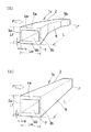
以下、本発明アルミニウム合金プロテクタの実施の形態について具体的に説明する。図1(a)、(b) は、本発明アルミニウム合金プロテクタの一態様を各々示す斜視図である。
【0023】
先ず、図1 (a) において、アルミニウム合金プロテクタ1aは、略正方形の矩形断面形状を有するアルミニウム合金押出中空形材2 からなる。7 は中空形材2 の中空部、4a、4bは略正方形の断面を構成する二つの横壁(横壁部とも言う)、3a、3bは略正方形の断面を構成する二つの縦壁(縦壁部とも言う)である。各横壁4a、4b同士、各縦壁3a、3b同士は互いに略平行に配置されるとともに、各横壁と各縦壁同士は互いに略直角に交わる。
【0024】
図1(a)、(b) の態様において、プロテクタ1a (中空形材2)は、車体衝突時の図の左側からの荷重方向 (横方向、矢印F)に対し、略直角方向に延在するように略水平配置されて使用される。
【0025】
図1 (a) の態様では、プロテクタ1a (中空形材2)は、軸方向に延在する直線的な中央部6 を有するとともに、軸方向 (長手方向) の両端部5a、5bが、車両後方(図の右側) に向かって湾曲している。
【0026】
図1 (b) のプロテクタ1bは、上記図1 (a) のプロテクタ1aのような両端の湾曲部5a、5bが無く、軸方向に直線的となっている以外は、プロテクタ1aと同じ構造、形状である。このようなプロテクタの軸方向乃至長手方向の形状は、トラックのフロント車体設計に応じて、適宜選択される。
【0027】
上記図1 (a) のプロテクタ1aのような両端の湾曲部5a、5bは、図1 (b) のような直線的な中空形材2 をアルミニウム合金の熱間押出加工によって得た後、この中空形材2 の両端を曲げ加工することによって、中空形材と一体に、しかも簡便に得ることができる。したがって、本発明アルミニウム合金プロテクタは、所望の曲げ角度や長さの両端の湾曲部を、トラックのフロント車体設計に応じて、一体的に形成できる利点がある。
【0028】
因みに、鋼はこのような中空形材を押出加工することができず、鋼製プロテクタを得るためには、鋼板を中空状に成形加工後に溶接乃至機械的な接合で中空材化するか、コの字状に成形した2 個の部品を対向して突き合わせて、溶接乃至機械的な接合で中空材化する。このように、中空状鋼製プロテクタを得るためには上記溶接等の手段を用いないと一体には形成できず、上記両端の湾曲部5a、5bも製作しにくい。
【0029】
以下に、本発明アルミニウム合金プロテクタの断面形状について説明する。
ここで、図1(a)、(b) の本発明アルミニウム合金プロテクタ1a、1bにおいて、縦壁部3a、3b(3a が前面側縦壁、3bが後面側縦壁) の各厚みをt f 、各長さを Lf および横壁部4a、4b(4a が上側横壁、4bが下側横壁) の各厚みをt w 、各長さをL wとし、プロテクタ (中空形材2)の長さをL とする。
【0030】
本発明では、本発明プロテクタと断面形状が類似の、乗用車用のバンパ補強材に通常用いられる、0.2%耐力が300MPa以上の高強度7000系アルミニウム合金だけではなく、0.2%耐力が250MPa以下である、6063などの汎用6000系アルミニウム合金などをプロテクタに用いることも重要な目的としている。
【0031】
勿論、本発明において、プロテクタを高圧壊強度化するために、高強度な7000系アルミニウム合金を用いても良い。7000系アルミニウム合金を用いれば、プロテクタ (中空材) を構成する各壁部のより薄肉化による、軽量化も図れる等の利点がある。ただ、この7000系は、高強度であるがゆえに、6000系アルミニウム合金などに比して、厚肉化するほど押出加工などの生産性が劣り、高強度化のための調質処理( 熱処理) が煩雑であるなどの中空材製造上の問題がある。このためプロテクタに、6000系アルミニウム合金なども用いることができれば、このような問題が解消される。
【0032】
ただ、0.2%耐力が250MPa以下である、これら6000系などのアルミニウム合金を用いる場合、より高強度な7000系アルミニウム合金を用いる場合に比して、プロテクタの圧壊強度を普通鋼製並に高め、鋼製プロテクタに対する軽量化効果を高めることは、格段に難しい課題となる。
【0033】
これに対し、本発明では、プロテクタの矩形中空断面を構成する各横壁部4a、4bの厚みt w を4 〜8mm とするとともに、この各横壁部4a、4bの厚みt w を、各縦壁部3a、3bの厚みt f よりも厚くしたことで解決している。これによって、高強度7000系アルミニウム合金だけでなく、0.2%耐力が250MPa以下の低強度の6000系などのアルミニウム合金を用いた場合でも、プロテクタの圧壊強度を普通鋼製並に高め、鋼製プロテクタに対する軽量化効果を高める課題を解決している。
【0034】
各横壁部の厚みt w が4mm 以下では、鋼製プロテクタの通常使用される壁部厚み3 〜4 mmよりも薄くなり、トラック衝突時の前記大荷重に対しての圧壊強度への寄与度が高い横壁部の厚みt w が不足し、普通鋼製プロテクタ並の強度が得られない。一方、各横壁部の厚みt w が8mm 以上では、重量が増加し、鋼製プロテクタに対する軽量化効果がなくなる。
【0035】
一方、各縦壁部3a、3bの厚みt f は、横壁部の厚みt w で主として定まるアルミニウム合金プロテクタの圧壊強度を、上記鋼製プロテクタ並に保証できる以上の厚さとし、軽量化するために、横壁部の厚みt w よりも薄くする。各横壁部の厚みt w が4 〜8mm であるので、各縦壁部の好ましい厚みt f の範囲は3 〜6mm である。これを、t f とt w との両者の関係で言うと、t f /t wを0.3 〜0.7 とすることが好ましい。t f /t wが0.3 未満ではt f が薄くなり過ぎて圧壊強度が低下するか、t w が厚くなり過ぎて軽量化効果が出ない可能性がある。一方、t f /t wが0.7 を越えては、横壁部と縦壁部との厚みが同じ従来技術に近くなり、圧壊強度を高められない可能性がある。
【0036】
なお、二つの横壁部4a、4bの厚みt w 、二つの縦壁部3a、3bの厚みt f は、横壁部同士、縦壁部同士で、図1 のプロテクタのように、必ずしも同じとする必要は無い。例えば、下側の横壁部4aを上側の横壁部4bよりも厚くする、前面側の縦壁部3aを後面側の縦壁部3bよりも厚くするなど、上記範囲で、横壁部同士、縦壁部同士の互いの厚みを変えても良い。中空形材2 をアルミニウム合金の熱間押出加工によって得る場合、このように互いの壁の厚みが異なる中空形材2 を自由に、かつ簡便に得やすいという利点もある。
【0037】
本発明プロテクタの矩形 (四角形) 中空断面の形状は、0.2%耐力が250MPa以下の低強度の6000系などのアルミニウム合金を用いた場合でも、プロテクタの圧壊強度を普通鋼製並に高めるためには、正方形形状であることが最も好ましい。前記横壁部の厚みt w の圧壊強度向上効果は、各横壁部の長さL w が、各縦壁部の長さ L fと同じ正方形形状の場合に、最大に発揮される。したがって、L w がL f に対し、長過ぎても、短過ぎても、言い換えると、縦に長い、あるいは横に長い長方形となるほど、前記横壁部の厚みt w の圧壊強度向上効果が低下する。ただ厳密に正方形形状である必要は無く、正方形に近ければ、この効果は変わらない。この効果が変わらない範囲は、概ね L f /L w が0.8 〜1.2 の範囲である。
【0038】
また、この範囲で、横壁部同士、縦壁部同士で、必ずしも互いの長さL w 、 fを同じとする必要は無く、上記範囲で互いの長さを変えても良い。この場合、各横壁4a、4b同士、各縦壁3a、3b同士は互いに平行ではなく、一定の角度をもって配置されるとともに、各横壁と各縦壁同士は互いに直角にではなく、一定の角度をもって交わる。例えば、本発明プロテクタの前面縦壁部3aの長さを後面側の縦壁部3bよりも長くすれば、プロテクタの前面側から後面側へ角度のついたテーパ状のプロテクタが得られ、上記長さ関係を逆にすれば、その逆のテーパ状のプロテクタも得られる。これによって、圧壊強度の制御ができ、デザインや接合、あるいは配置上の自由度も増す。アルミニウム合金の熱間押出加工であれば、このような中空形材を自由に、かつ簡便に得やすいという利点もある。
【0039】
アルミニウム合金プロテクタの本実施態様では、矩形中空断面の形状は口形の例を示した。軽量化の点からは、この口形の中空構造が好ましいし、口形の中空構造で高圧壊強度化が可能である。ただ、トラックの車種や法規によって要求圧壊強度が異なり、また、軽量化よりも高圧壊強度が要求されるような場合もある。したがって、このような場合には、アルミニウム合金プロテクタの圧壊強度をより高めるために、例えば、図1 の矩形中空部7 内に補強用の中リブを横方向や縦方向に加えた断面形状とし、断面形状を日形、田形、目形等にすることなども可能である。
【0040】
なお、図1 に示すアルミニウム合金プロテクタ1 の長さL は、トラックの車幅やフロント設計などに応じて適宜決定されるが、概ね60〜200mm 程度である。
【0041】
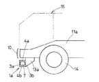
次に、本発明アルミニウム合金プロテクタの一使用態様 (アンダーランプロテクタ装置の態様) を図2 、3 を用いて説明する。図2 、3 は、各々トラックのフロント部分にアルミニウム合金プロテクタを取り付けた要部を示す平面図、図3 は図2 の正面図である。
【0042】
図2 、3 において、10はトラックのフロントに車幅方向に延在するバンパ、11a 、11b は車体の長さ方向に延在する車体フレーム (サイドレール、シャーシーフレーム) 、12はサイドレールをつなぎ車幅方向に延在するファーストクロスメンバ、14はフロントタイヤ、15はトラック車体である。
【0043】
また、13a 、13b は、例えば、図1 (a) のアルミニウム合金プロテクタ1aを後方から支持するとともに、車体フレーム11a 、11b に接続しているブラケットである。プロテクタ1aは、トラックフロントバンパの下側に乗用車が滑り込むことを防止するため、トラックの車高に応じて、フロントバンパ10の下側の適宜の高さに配置される。
【0044】
ブラケット13a 、13b によるプロテクタ1aの支持やブラケットの構造は、詳細に図示はしないが、公知のアンダーランプロテクタ装置の取り付け態様を適宜採用できる。例えば、板状あるいは箱状のブラケット先端部にフランジを設けて、このフランジの前面とプロテクタ1aの後面側の縦壁3bの背面 (裏面) とを接合するか、ブラケット先端部を直接縦壁3bの背面と接合する。接合は溶接や機械的な接合を適宜組み合わせて行なわれる。なお、図1(b)のプロテクタ1bなど、本発明の他のプロテクタでも、これらの方法で同様に接合できる。
【0045】
図4 に正面図で示すプロテクタ1cは、上記ブラケット先端部のフランジによって、接合支持する態様を示している。図4 のプロテクタ1cは、後面側の縦壁部3bに二箇所、間隔を開けて、中空部7 内方向に凹む凹部8a、8bを設けている。この凹部8a、8bの縦壁部とブラケット19先端部のフランジ16とを、その形成する空間9a、9bとフランジ16の貫通孔18a 、18b を介して、ボルト締結手段17a 、17b によって接合することで、プロテクタ1cはブラケット19と接合、支持される。なお、ブラケット19は板状、箱状の適宜の構造を有し、図示しない上方の車体フレームに接続され、この車体フレームから斜め下方 (車体前方) に向かって、張り出されている。
【0046】
プロテクタ1cの断面形状 (正方形断面、横壁部4a、4bの各厚みが縦壁部3a、3bの各厚みよりも厚い点など) は、上記凹部8a、8bを除き、前記図1 (a) のプロテクタ1aや図1 (b) のプロテクタ1bと同じである。プロテクタ1cの両端が湾曲しているか、全長が直線的であるかは、いずれでも良い。
【0047】
本発明プロテクタとしての要求特性を満足するアルミニウム合金としては、通常、この種構造部材用途に汎用される、AA乃至JIS 5000系、6000系、7000系等の耐力の比較的高い汎用合金であって、調質されたアルミニウム合金から選択して用いられる。ただ、この中でも、前記した通り、比較的中空材として製造しやすい、特に、6063汎用合金などのAl−Si−Mg系の6000系アルミニウム合金が好ましい。ただ、前記したように、より高い圧壊強度が要求されるような場合には、Al−Zn−Mg系、あるいは Al−Zn−Mg−Cu系の7000系のアルミニウム合金を用いても良い。これらのアルミニウム合金材を、O 、T4、T5、T6、T7などの適宜の調質を施されて所望の耐力や機械的性質とする。
【0048】
本発明プロテクタを構成するアルミニウム合金中空材は、前記した各利点も含め、押出中空形材が好ましい。熱間押出加工であれば、矩形中空断面の形状を、中空材の長手 (軸) 方向に渡って同一に製造できる。但し、可能であれば、アルミニウム合金の圧延板を中空状に成形および接合部を溶接接合した中空材なども用いて良い。
【0049】
【発明の効果】
本発明によれば、アルミニウム合金製プロテクタ自体の圧壊強度を鋼製プロテクタ並に高め、しかも鋼製プロテクタに比して軽量化効果が高い車両フロントアンダーランプロテクタを提供することができる。このため、トラック車体の軽量化を促進でき、アルミニウム合金材の用途も一層拡大するものであり、工業的な価値が大きい。
【図面の簡単な説明】
【図1】本発明に係るプロテクタの一実施態様を示し、図1(a)は両端が湾曲したプロテクタ、図1(b)は直線的なプロテクタを各々示す斜視図である。
【図2】本発明に係るプロテクタの一使用態様を示す平面図である。
【図3】図2 の正面図である。
【図4】本発明に係るプロテクタの別の態様を示す正面図である。
【符号の説明】
1:フロントアンダーランプロテクタ、2:中空材、3:縦壁部、4:横壁部、
5:湾曲部、6:中央部、7:中空部、8:凹み部、9:空間、10: バンパ、
11: 車体フレーム、12: ファーストクロスメンバ、13: ブラケット、
14: フロントタイヤ、15: 車体、16: フランジ、17: ボルト締結手段、
18: 貫通孔、19: ブラケット、
t f : 縦壁部の厚み、L f : 縦壁部の長さ、t w : 横壁部の厚み、
L w : 横壁部の長さ、L : プロテクタの長さ、[0001]
TECHNICAL FIELD OF THE INVENTION
The present invention relates to a vehicle front underrun protector having excellent crush strength against a load at the time of a vehicle collision.
[0002]
[Prior art]
In the event of a frontal collision between a vehicle such as a truck and a passenger car, the lower part of the front bumper is to prevent passenger cars from slipping under the front (front) bumper of the truck and to ensure passenger safety. , A front underrun protector (a device for preventing undercarriage of a vehicle, hereinafter simply referred to as a protector) is disposed.
[0003]
The structure of the protector for trucks is basically made of a hollow material having a rectangular cross section such as a mouth and having a cross section extending in the longitudinal direction (axial direction). And it is arrange | positioned under the truck front bumper so that it may extend substantially horizontally in the vehicle width direction.
[0004]
At the time of a frontal collision between a vehicle such as the truck and a passenger car, a local collision load of 5 to 20 tons is applied to the protector. Therefore, the protector is required to have a crushing strength that can withstand this impact load (lateral load). For this reason, steel protectors made of high-strength steel such as high strength have been mainly used.
[0005]
Incidentally, the collision load applied to the bumper at the time of a vehicle collision with another passenger vehicle is about 10 to 15 tons at the time of a full collision such as a barrier collision. However, if the local collision load of a truck or the like is converted to about 5 to 6 tons, it becomes significantly lighter than the local collision load of the truck protector and the required crushing strength.
[0006]
In order to increase the strength of the protector as a device, various proposals have conventionally been made to reinforce a protector support structure such as a bracket for supporting the protector (attached to a front end portion of a vehicle body frame) (for example, see Patent Document 1). It has also been proposed to provide a cylindrical impact energy absorbing device made of FRP between the bracket and the protector (see Patent Document 2).
[0007]
[Patent Document 1]
JP-A-2002-302000 (pages 1-2, FIG. 1)
[Patent Document 2]
JP-A-2000-296743 (pages 1-2, FIG. 1)
[0008]
In recent years, in order to reduce the body weight of trucks, the use of aluminum alloy extruded hollow sections and the like for these protectors instead of conventionally used steel has begun to be studied.
[0009]
However, the reinforcement of the protector support structure proposed in the past, such as
[0010]
When the aluminum alloy protector is designed to have the same rectangular cross-sectional shape as the steel protector, the crushing strength against the large collision load is insufficient. On the other hand, if the thickness of the aluminum alloy protector (the thickness of the wall constituting the rectangular cross section) is increased in order to increase the crushing strength, the weight of the protector increases, and the weight reduction effect on the steel protector is lost. Is
[0011]
On the other hand, it has been disclosed that, for example, the protector is made of an extruded aluminum material, and a number of through holes (square holes) are formed in an axial direction of the protector so that a cross section orthogonal to the vehicle width direction has a number of holes. (See Patent Document 3). In this Patent Document 3, at the time of a collision load, the hole is crushed to absorb the collision energy by crushing the hole. In comparison, the purpose is to increase the crushing strength.
[0012]
[Patent Document 3]
JP-A-2000-272444 (pages 1-2, FIG. 1)
[0013]
[Problems to be solved by the invention]
However, Patent Literature 3 can certainly reduce the weight compared to the solid material, but the crushing strength is reduced while reducing the weight compared to the rectangular hollow cross-sectional shape such as the mouth shape, which is the object. Can not be enhanced. As a result, it is difficult to commercialize an aluminum alloy protector instead of a steel protector.
[0014]
That is, in order to provide a large number of holes and reduce the weight as much as a rectangular hollow cross-section such as a mouth as in Patent Document 3, it is necessary to provide an excessively large hole or an excessively large number of holes. However, in this case, inevitably the thickness of each of the many walls constituting the hole becomes thin. Here, Patent Document 3 has a large number of walls constituting a hole, and therefore, when assuming an aluminum alloy profile, the lateral crush strength is one sheet larger than that of a rectangular hollow cross-sectional shape such as a mouth. The thickness of the wall per sheet becomes thinner, which is rather disadvantageous. For this reason, the crushing strength cannot be increased more than a rectangular hollow cross-sectional shape such as a mouth shape, and conversely, the crushing strength may be lower than that of a rectangular hollow cross-sectional shape such as a mouth shape.
[0015]
On the other hand, in order to increase the crushing strength, on the other hand, it is inevitable to increase the thickness of a large number of walls constituting the hole. The number of walls for thickening is increased, and the weight is sacrificed at the expense of disadvantage, and the effect of reducing the weight as compared with the solid material is reduced.
[0016]
As described above, since it is difficult to reduce the weight and increase the high-pressure breaking strength of an aluminum alloy protector, it has been difficult to put it to practical use instead of a steel protector.
[0017]
Therefore, an object of the present invention is to provide a vehicle front underrun protector made of an aluminum alloy, which has a crushing strength of the protector itself as high as that of a steel protector and has a higher weight-saving effect than a steel protector. .
[0018]
[Means for Solving the Problems]
In order to achieve this object, the gist of the vehicle front underrun protector according to the present invention is that the cross-sectional shape is made of a hollow aluminum alloy material having a rectangular cross section, and that the thickness of a horizontal wall portion constituting the rectangular hollow cross section is 4 to 8 mm. The thickness of the horizontal wall is made larger than the thickness of the vertical wall constituting the rectangular hollow cross section. Here, the distinction between the horizontal wall portion and the vertical wall portion is made based on a rectangular hollow cross-section arrangement state assuming a use mode of the protector (a case where the protector is arranged to extend substantially in the vehicle width direction). You.
[0019]
In the protector, not only the steel protector but also, generally, the horizontal wall portion and the vertical wall portion forming the rectangular cross section of the hollow member of the protector have substantially the same thickness. On the other hand, in the present invention, first, the thickness of the horizontal wall portion forming the rectangular cross-sectional shape of the hollow member is set to 4 to 8 mm. As described above, in the present invention, the thickness of the horizontal wall portion is slightly increased from the thickness of the normally used wall portion of the steel protector of 3 to 4 mm and the thickness of the vertical wall portion forming the rectangular hollow cross section. The crushing strength of the aluminum alloy protector is, for example, one of the concrete guides, a protector having a generally square cross section made of ordinary steel (wall thickness: 3 to 4 mm, wall length: 60 to 40 mm) currently used. 100mm).
[0020]
On the other hand, the thickness of the vertical wall is made thinner than that of the horizontal wall (the thickness of the horizontal wall is made thicker than the thickness of the vertical wall) to increase the weight saving effect on the steel protector. At this time, the thickness of the vertical wall portion is set to a thickness that can guarantee the crushing strength of the aluminum alloy protector to be equal to that of the steel protector, and is not further reduced.
[0021]
The lateral wall portion of the aluminum alloy protector is parallel to the direction of the collision load (lateral load) of 5 to 20 tons in a truck collision. For this reason, the degree of contribution to the crush strength against this large load is higher than that of the vertical wall. For this reason, in the present invention, the thickness of the side wall portion having a high contribution to the crushing strength is made relatively thick. And, by this, the thickness of the vertical wall portion can be made thinner than that of the horizontal wall portion so as not to lower the crushing strength of the increased aluminum alloy protector below that of the steel protector, thereby reducing the weight of the steel protector. Can be increased.
[0022]
BEST MODE FOR CARRYING OUT THE INVENTION
Hereinafter, embodiments of the aluminum alloy protector of the present invention will be specifically described. FIGS. 1A and 1B are perspective views showing one embodiment of the aluminum alloy protector of the present invention.
[0023]
First, in FIG. 1A, an
[0024]
1 (a) and 1 (b), the
[0025]
In the embodiment shown in FIG. 1A, the
[0026]
The
[0027]
The
[0028]
By the way, steel cannot extrude such a hollow profile, and in order to obtain a steel protector, a steel plate is formed into a hollow shape and then hollowed by welding or mechanical joining, or The two parts formed in a U-shape are butted against each other and made into a hollow material by welding or mechanical joining. As described above, in order to obtain the protector made of hollow steel, it is not possible to integrally form the protector unless the above-mentioned means such as welding is used, and it is difficult to manufacture the
[0029]
Hereinafter, the cross-sectional shape of the aluminum alloy protector of the present invention will be described.
Here, FIG. 1 (a), the present invention an
[0030]
In the present invention, not only a high-strength 7000 series aluminum alloy having a 0.2% proof stress of 300 MPa or more but also a 0.2% proof stress, which is generally used for a bumper reinforcing material for a passenger car and has a similar cross-sectional shape to the protector of the present invention, has a 0.2% proof stress. It is also an important object to use a general-purpose 6000 series aluminum alloy such as 6063 having 250 MPa or less for the protector.
[0031]
Of course, in the present invention, a high-strength 7000 series aluminum alloy may be used to increase the high-pressure breaking strength of the protector. The use of a 7000 series aluminum alloy has the advantage that the walls of the protector (hollow member) can be made thinner and lighter. However, since the 7000 series has high strength, productivity such as extrusion processing is inferior as thicker as compared with 6000 series aluminum alloys and the like, and the refining treatment (heat treatment) for increasing the strength is performed. However, there is a problem in the production of the hollow material, such as that the method is complicated. Therefore, if a 6000 series aluminum alloy or the like can be used for the protector, such a problem is solved.
[0032]
However, when using aluminum alloys such as 6000 series having a 0.2% proof stress of 250 MPa or less, the crushing strength of the protector is equal to that of ordinary steel, as compared with the case of using a higher strength 7000 series aluminum alloy. Elevating and increasing the weight saving effect on steel protectors is a particularly difficult task.
[0033]
In contrast, in the present invention, each
[0034]
The thickness t w is 4mm or less in each lateral wall portion is made thinner than the normal wall thickness 3 to 4 mm to be used for steel protector, contribution to crushing strength against the large load at the time of track collision lack of thickness t w of the high lateral wall portion, not ordinary steel protector average of strength can not be obtained. On the other hand, in the lateral wall portion thickness t w is more than 8mm of the weight is increased, weight reduction ineffective against steel protector.
[0035]
On the other hand, the
[0036]
The thickness t w of the two
[0037]
The shape of the rectangular (square) hollow cross section of the protector of the present invention is to increase the crushing strength of the protector to that of ordinary steel even when using a low-strength 6000 series aluminum alloy having a 0.2% proof stress of 250 MPa or less. Is most preferably a square shape. Crushing strength improving effect of the thickness t w of said lateral wall portion has a length L w of the lateral wall portions, in the case of the same square shape as the length L f of the vertical wall portion, is exhibited to the maximum. Thus, for L w is L f, be too long, be too short, in other words, vertically long, or indeed a long rectangle side, crushing strength improving effect of the thickness t w of said lateral wall portion is reduced . However, it is not necessary that the shape be strictly square. If the shape is close to a square, this effect does not change. Extent to which this effect does not change, generally L f / L w is in the range of 0.8 to 1.2.
[0038]
In this range, the lengths Lw and f of the horizontal wall portions and the vertical wall portions do not necessarily have to be the same, and the lengths may be changed in the above range. In this case, the
[0039]
In the present embodiment of the aluminum alloy protector, the example of the rectangular hollow cross section has a mouth shape. From the viewpoint of weight reduction, this mouth-shaped hollow structure is preferable, and the mouth-shaped hollow structure enables high-pressure breaking strength. However, the required crushing strength varies depending on the type of truck and the regulations, and in some cases, the crushing strength is required rather than the weight reduction. Therefore, in such a case, in order to further increase the crushing strength of the aluminum alloy protector, for example, a cross-sectional shape in which a reinforcing middle rib is added in the horizontal or vertical direction in the rectangular
[0040]
The length L of the aluminum alloy protector 1 shown in FIG. 1 is determined as appropriate according to the width of the truck and the front design, but is generally about 60 to 200 mm.
[0041]
Next, one mode of use of the aluminum alloy protector of the present invention (mode of the underrun protector device) will be described with reference to FIGS. FIGS. 2 and 3 are plan views each showing a main part of the truck where an aluminum alloy protector is attached to the front portion, and FIG. 3 is a front view of FIG.
[0042]
2 and 3,
[0043]
13a and 13b are, for example, brackets that support the
[0044]
The support of the
[0045]
The
[0046]
The cross-sectional shape of the
[0047]
The aluminum alloy satisfying the characteristics required for the protector of the present invention is a general-purpose alloy having a relatively high proof stress, such as AA to JIS 5000 series, 6000 series, and 7000 series, which is generally used for structural members of this kind. Selected from tempered aluminum alloys. However, among them, as described above, an Al-Si-Mg-based 6000 series aluminum alloy such as a 6063 general-purpose alloy, which is relatively easy to manufacture as a hollow material, is particularly preferable. However, as described above, when higher crush strength is required, an Al-Zn-Mg-based or Al-Zn-Mg-Cu-based 7000-based aluminum alloy may be used. These aluminum alloy materials are subjected to appropriate refining such as
[0048]
The hollow aluminum alloy material constituting the protector of the present invention is preferably an extruded hollow material including the advantages described above. In the case of hot extrusion, the shape of a rectangular hollow cross section can be made uniform in the longitudinal (axial) direction of the hollow material. However, if possible, a hollow material obtained by forming a rolled plate of an aluminum alloy into a hollow shape and welding and joining the joints may be used.
[0049]
【The invention's effect】
According to the present invention, it is possible to provide a vehicle front under-run protector that increases the crushing strength of the aluminum alloy protector itself to the same level as that of the steel protector, and has a higher weight reduction effect than the steel protector. For this reason, the weight reduction of the truck body can be promoted, the use of the aluminum alloy material is further expanded, and the industrial value is great.
[Brief description of the drawings]
1A and 1B show an embodiment of a protector according to the present invention. FIG. 1A is a perspective view showing a protector having both ends curved, and FIG. 1B is a perspective view showing a linear protector.
FIG. 2 is a plan view showing one use mode of the protector according to the present invention.
FIG. 3 is a front view of FIG. 2;
FIG. 4 is a front view showing another embodiment of the protector according to the present invention.
[Explanation of symbols]
1: front underrun protector, 2: hollow material, 3: vertical wall, 4: horizontal wall,
5: curved portion, 6: central portion, 7: hollow portion, 8: concave portion, 9: space, 10: bumper,
11: body frame, 12: first cross member, 13: bracket,
14: front tire, 15: body, 16: flange, 17: bolt fastening means,
18: through hole, 19: bracket,
t f: vertical wall portion of the thickness, L f: vertical wall portion of the length, t w: the lateral wall portion of the thickness,
L w: the length of the lateral wall portion, L: the length of the protector,
Claims (6)
Priority Applications (1)
| Application Number | Priority Date | Filing Date | Title |
|---|---|---|---|
| JP2002344003A JP2004175228A (en) | 2002-11-27 | 2002-11-27 | Vehicle front underrun protector |
Applications Claiming Priority (1)
| Application Number | Priority Date | Filing Date | Title |
|---|---|---|---|
| JP2002344003A JP2004175228A (en) | 2002-11-27 | 2002-11-27 | Vehicle front underrun protector |
Publications (1)
| Publication Number | Publication Date |
|---|---|
| JP2004175228A true JP2004175228A (en) | 2004-06-24 |
Family
ID=32705643
Family Applications (1)
| Application Number | Title | Priority Date | Filing Date |
|---|---|---|---|
| JP2002344003A Pending JP2004175228A (en) | 2002-11-27 | 2002-11-27 | Vehicle front underrun protector |
Country Status (1)
| Country | Link |
|---|---|
| JP (1) | JP2004175228A (en) |
Cited By (7)
| Publication number | Priority date | Publication date | Assignee | Title |
|---|---|---|---|---|
| JP2008189273A (en) * | 2007-02-08 | 2008-08-21 | Nissan Diesel Motor Co Ltd | Front underrun protector |
| JP2008273271A (en) * | 2007-04-25 | 2008-11-13 | Kobe Steel Ltd | Under-run protector of truck |
| JP2009101848A (en) * | 2007-10-23 | 2009-05-14 | Kobe Steel Ltd | Vehicular underrun protector |
| WO2012081176A1 (en) | 2010-12-15 | 2012-06-21 | Udトラックス株式会社 | Under-run protector for vehicle |
| WO2015080088A1 (en) | 2013-11-28 | 2015-06-04 | ダイムラー・アクチェンゲゼルシャフト | Structure for underrun protector |
| WO2015080087A1 (en) | 2013-11-28 | 2015-06-04 | ダイムラー・アクチェンゲゼルシャフト | Structure for underrun protector |
| WO2015080089A1 (en) | 2013-11-28 | 2015-06-04 | ダイムラー・アクチェンゲゼルシャフト | Structure for underrun protector |
-
2002
- 2002-11-27 JP JP2002344003A patent/JP2004175228A/en active Pending
Cited By (13)
| Publication number | Priority date | Publication date | Assignee | Title |
|---|---|---|---|---|
| JP2008189273A (en) * | 2007-02-08 | 2008-08-21 | Nissan Diesel Motor Co Ltd | Front underrun protector |
| JP2008273271A (en) * | 2007-04-25 | 2008-11-13 | Kobe Steel Ltd | Under-run protector of truck |
| JP2009101848A (en) * | 2007-10-23 | 2009-05-14 | Kobe Steel Ltd | Vehicular underrun protector |
| WO2012081176A1 (en) | 2010-12-15 | 2012-06-21 | Udトラックス株式会社 | Under-run protector for vehicle |
| CN103260961A (en) * | 2010-12-15 | 2013-08-21 | Ud卡车株式会社 | Under-run protector for vehicle |
| JP5795332B2 (en) * | 2010-12-15 | 2015-10-14 | Udトラックス株式会社 | Vehicle underrun protector |
| WO2015080087A1 (en) | 2013-11-28 | 2015-06-04 | ダイムラー・アクチェンゲゼルシャフト | Structure for underrun protector |
| WO2015080089A1 (en) | 2013-11-28 | 2015-06-04 | ダイムラー・アクチェンゲゼルシャフト | Structure for underrun protector |
| WO2015080088A1 (en) | 2013-11-28 | 2015-06-04 | ダイムラー・アクチェンゲゼルシャフト | Structure for underrun protector |
| CN105793117A (en) * | 2013-11-28 | 2016-07-20 | 戴姆勒股份公司 | Structure for underrun protector |
| US9764707B2 (en) | 2013-11-28 | 2017-09-19 | Daimler Ag | Structure of underrun protection |
| US10118580B2 (en) | 2013-11-28 | 2018-11-06 | Daimler Ag | Structure of underrun protection |
| US10286866B2 (en) | 2013-11-28 | 2019-05-14 | Daimler Ag | Structure of underrun protection |
Similar Documents
| Publication | Publication Date | Title |
|---|---|---|
| CN102343878B (en) | Impact absorbing device for vehicle and bumper device for vehicle | |
| JP6170895B2 (en) | Collision resistant parts for automobiles | |
| JP4733702B2 (en) | Vehicle crash box | |
| US7874600B2 (en) | Bumper system for vehicle | |
| JP4636799B2 (en) | Support structure made of hollow steel long section material for automobile | |
| US20050225115A1 (en) | Beam | |
| JP2005532207A5 (en) | ||
| JP2004262300A (en) | Bumper reinforcement | |
| JP4787728B2 (en) | Body bumper beam and body shock absorber | |
| JP2006335241A (en) | Bumper stay and bumper device | |
| JP2004175228A (en) | Vehicle front underrun protector | |
| JP4015896B2 (en) | Car body structural materials and anti-collision reinforcement | |
| JP4035292B2 (en) | Bumper reinforcement with excellent offset impact | |
| JP2006248461A (en) | Automobile panel structure | |
| JP4956081B2 (en) | Body bumper beam and body shock absorber | |
| JP2006111228A (en) | Truck chassis frame and aluminum alloy for frame | |
| JP4647805B2 (en) | Car side step | |
| JP5235007B2 (en) | Crash box | |
| JP2010089783A (en) | Bumper structure for passenger car | |
| JP2008189273A (en) | Front underrun protector | |
| JPH07145843A (en) | Energy absorbing member made of aluminum alloy for automobile | |
| JP2002012104A (en) | Bumper stay | |
| JP2005254829A (en) | Bumper stay and bumper structure | |
| EP2113423B1 (en) | Bumper system for vehicle | |
| JP5237927B2 (en) | Automotive roof reinforcement member and design method thereof |
Legal Events
| Date | Code | Title | Description |
|---|---|---|---|
| A621 | Written request for application examination |
Free format text: JAPANESE INTERMEDIATE CODE: A621 Effective date: 20040922 |
|
| A131 | Notification of reasons for refusal |
Free format text: JAPANESE INTERMEDIATE CODE: A131 Effective date: 20061205 |
|
| A521 | Written amendment |
Free format text: JAPANESE INTERMEDIATE CODE: A523 Effective date: 20070201 |
|
| A02 | Decision of refusal |
Free format text: JAPANESE INTERMEDIATE CODE: A02 Effective date: 20070417 |