JP2004173785A - Rotary cleaning body, production method thereof, suction port body of vacuum cleaner, and production method thereof - Google Patents
Rotary cleaning body, production method thereof, suction port body of vacuum cleaner, and production method thereof Download PDFInfo
- Publication number
- JP2004173785A JP2004173785A JP2002341339A JP2002341339A JP2004173785A JP 2004173785 A JP2004173785 A JP 2004173785A JP 2002341339 A JP2002341339 A JP 2002341339A JP 2002341339 A JP2002341339 A JP 2002341339A JP 2004173785 A JP2004173785 A JP 2004173785A
- Authority
- JP
- Japan
- Prior art keywords
- brush
- shaft
- mounting member
- base
- cleaning
- Prior art date
- Legal status (The legal status is an assumption and is not a legal conclusion. Google has not performed a legal analysis and makes no representation as to the accuracy of the status listed.)
- Pending
Links
Images


Abstract
Description
【0001】
【発明の属する技術分野】
本発明は、軸体の外周面に軸方向に沿って螺旋状に突出した清掃部材が取り付けられた回転清掃体、この回転清掃体の製造方法、この回転清掃体を備えた電気掃除機の吸込口体、およびこの吸込口体の製造方法に関する。
【0002】
【従来の技術】
従来、この種の回転清掃体は、外周面に軸方向に沿って螺旋状に巻回した断面凹状の複数の取付凹部としての係合凹部が設けられた細長円筒状のシャフトを備えている。このシャフトの各係合凹部は、このシャフトの周方向に沿って互いに等間隔に離間された位置に設けられている。また、このシャフトは、アルミニウムによるねじり押し出し成形により各係合凹部が螺旋状にねじられて成形されている。
【0003】
さらに、これら各係合凹部のそれぞれには、細長断面三角形状の清掃部材としてのブレードの基端側が長手方向に沿って挿入されて係合されている。そして、これら各ブレードは、これら各ブレードの基端側がシャフトの各係合凹部に係止されて、このシャフトの外周面に対して螺旋状に巻回した状態で壁状に突出している。
【0004】
また、シャフトの中心には、このシャフトの軸方向に沿ったピン挿通孔が貫通した状態で開口されている。このピン挿通孔には、細長棒状の軸体としてのピンが圧入されて一体的に取り付けられている。そして、このピンは、シャフトの両端面から両端部のそれぞれが突出した状態でこのシャフトのピン挿通孔に挿通されている(例えば、特許文献1参照。)。
【0005】
【特許文献1】
特公平6−85752号公報(第2頁、図2および図3)
【0006】
【発明が解決しようとする課題】
しかしながら、上記回転清掃体では、シャフトに設けられた各係合凹部を螺旋状に巻回させるために、このシャフトをアルミニウムによるねじり押し出し成形によって成形させているので、歪みなどの発生により精度を確保することが容易ではなく、シャフトを回転させた際にぶれが生じやすいという問題を有している。
【0007】
本発明は、このような点に鑑みなされたもので、精度の確保が容易な回転清掃体、この回転清掃体の製造方法、この回転清掃体を備えた電気掃除機の吸込口体、およびこの吸込口体の製造方法を提供することを目的とする。
【0008】
【課題を解決するための手段】
本発明は、軸方向に沿った挿通孔を有する筒状の取付部材の外周面から突出させて、この取付部材とは異なる材質の清掃部材を取付部材の軸方向に沿って取り付けた後、この取付部材の挿通孔に軸体を挿通するとともに、清掃部材が螺旋状になるように取付部材を周方向に向けてねじって軸体に取り付けたものである。そして、清掃部材を取付部材の外周面から突出させてこの取付部材の軸方向に沿って取り付ければよいので、この清掃部材による取付部材への取り付け精度の確保が容易となる。また、清掃部材を取付部材とは異なる材質としたので、取付部材をねじりに適した材質にできるとともに、清掃部材を清掃に適した材質にできるから、回転清掃体の製造性および清掃効率を向上できる。
【0009】
【発明の実施の形態】
以下、本発明の一実施の形態における電気掃除機の構成を図1ないし図7を参照して説明する。
【0010】
図1ないし図7において、1は掃除機本体で、この掃除機本体1は中空であり、内部に電動送風機2が収容されている。また、この掃除機本体1は、電動送風機2の駆動にて生じる吸気風とともに吸い込んだ塵埃を捕捉して集塵する。
【0011】
さらに、この掃除機本体1の前側略中央には、外部から空気を吸引する本体吸込口3が開口されている。この本体吸込口3には、湾曲可能な細長略円筒状の接続管としてのホース体4が連通接続されている。このホース体4の先端には、電動送風機2の動作モードなどが選択可能な手許操作部5が設けられている。
【0012】
そして、この手許操作部5には、掃除機本体1内の電動送風機2などの駆動状態を所定の状態に設定する複数の設定ボタン6が設けられているとともに、掃除する際に作業者が把持する把持部7が基端側に突設されている。また、この手許操作部5の先端には、伸縮可能な細長略円筒状の延長管8が着脱可能に連通接続されている。さらに、この延長管8の先端には、例えば室内の床面の絨毯などの上に設置させて、この絨毯上の塵埃を吸い込む吸込口体としての床ブラシ9が着脱可能に連通接続されている。
【0013】
そして、この床ブラシ9は、図1、図2および図7に示すように、前後方向である走行方向に対して横長で、後部略中央が後方に向けて突出する凸字状のケース体11を備えている。このケース体11における被掃除面としての床面と対向する下面には、細長矩形状の吸込口12が開口形成されている。この吸込口12は、ケース体11の走行方向の前側に偏位した位置に設けられており、このケース体11の走行方向に対する幅方向に沿った長手方向を有した横長矩形状に形成されている。
【0014】
さらに、このケース体11の吸込口12の内側には、細長略円筒状の回転清掃体としての回転ブラシ13が走行方向に向けて回転自在に軸支されて配設されている。この回転ブラシ13は、図1ないし図3に示すように、細長略円筒状の取付部材としてのブラシ台14を備えている。このブラシ台14は、変形可能でありねじりに適した部材、すなわちねじり加工が可能な程度の可撓性を有する材質、例えばプラスチックなどの硬質な部材などにて押し出し成形されて形成されている。
【0015】
また、このブラシ台14の外周面には、このブラシ台14の軸方向に沿った断面略凹状の係止凹部15が複数、例えば4つ設けられている。これら係止凹部15は、基端側から先端側に向かうに連れて徐々に拡開したテーパ状に形成されている。また、これら係止凹部15は、周方向に間隔をおいて等間隔な状態で直線状に設けられている。
【0016】
さらに、これら係止凹部15間に位置するブラシ台14の外周面には、このブラシ台14の軸方向に沿った断面略凹状の取付凹部としての係合凹部16が複数、例えば2つ設けられている。そして、これら係合凹部16は、ブラシ台14の軸中心を基準とした点対称な位置である、このブラシ台14の外周面における反対側の位置に設けられている。また、これら係合凹部16は、一対の係止凹部15間に位置するブラシ台14の外周面の幅方向における中央部に設けられている。
【0017】
ここで、このブラシ台14の各係合凹部16は、図2および図3に示すように、内部が周方向に幅広となる拡大部17と、この拡大部17から外周面に連通する幅狭な連通部18とにて、段差を設けて断面形状が先端幅狭の凹状に形成されている。ここで、これら係合凹部16の拡大部17は、基端側が断面凹弧状に形成されており、先端側の内縁が基端側に対向した平面状に形成されている。
【0018】
そして、これら各係合凹部16には、清掃部材としての掻取部材21の基端側が周方向に沿って係止されて取り付けられている。これら掻取部材21は、ブラシ台14の外周面にこのブラシ台14の軸方向に沿って壁状に突出して取り付けられている。そして、これら掻取部材21は、例えば軟質塩化ビニルなどにて細長平板状で長手方向の一側両面に肉厚に膨出する掻き出し部22を断面凹凸状に設けた弾性を有するブレード23を備えている。そして、このブレード23の長手方向の他縁には、このブレード23と同材質にて一体に細長略平板状のブレード取付部24が形成されている。
【0019】
また、ブラシ台14における係合凹部16が形成されていない係止凹部15間の外周面には、複数の円筒状の植毛凹部25が設けられている。これら植毛凹部25は、ブラシ台14における係合凹部16が形成されていない係止凹部15間の外周面の幅方向における中央部に設けられている。また、これら植毛凹部25は、このブラシ台14の係止凹部15に基端部が係止されて取り付けられた一対の掻取部材21それぞれに対する中間部に取り付けられている。さらに、これら植毛凹部25は、ブラシ台14の径方向に向けて開口しており、このブラシ台14の軸方向に沿って所定の間隔を介して設けられている。
【0020】
そして、これら植毛凹部25には、清掃部材としてのブラシ部材26がブラシ台14の外周面から突出した状態で取り付けられている。このブラシ部材26は、複数のブラシ毛27にて構成されており、このブラシ毛27は、清掃に適した部材であるブラシ台14とは異なる材質、例えば軟質塩化ビニルなどの合成樹脂などにより成形されている。また、このブラシ毛27は、複数本がまとめらてた状態で、ブラシ台14の各植毛凹部25に基端部が直接植毛されることにより取り付けられている。そして、複数本がまとめられたブラシ毛27の基端部を、ブラシ台14の外周面に設けられた各植毛凹部25に圧入して、これら複数のブラシ毛27を植毛することにより、図1ないし図3に示すように、このブラシ台14の外周面に対して垂直に壁状に突出し、このブラシ台14の軸方向に沿ったブラシ部材26を構成する。
【0021】
したがって、これらブラシ部材26は、外周面の各植毛凹部25にブラシ毛27が植毛されたブラシ台14を、長手方向の中心軸を中心として周方向に向けてねじることにより、このブラシ台14の外周面に螺旋状に旋回したブラシ毛27を形成させる。さらに、これらブラシ部材26は、ブラシ台14の外周面における長手方向の中心軸を中心とした互いに対向する位置に取り付けられている。
【0022】
一方、ブラシ台14の軸方向における両端部の中央部間には、このブラシ台14の軸方向に沿って貫通した貫通孔としてのシャフト挿通孔28が穿設されている。そして、このシャフト挿通孔28には、例えば鋼鉄やステンレス鋼(SUS)などの金属にて成形された中空パイプ状の軸体としての回転軸であるシャフト31が挿通される。そして、このシャフト31は、ブラシ台14より硬質な部材にて成形されており、このブラシ台14の両端部からこのシャフト31の両端部のそれぞれを突出させた状態で、このブラシ台14のシャフト挿通孔28に挿通されている。
【0023】
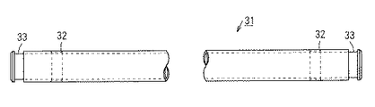
また、このシャフト31の両端部には、図4に示すように、このシャフト31の径方向に向けて貫通したピン挿通孔32が穿設されている。これらピン挿通孔32は互いに平行に形成されており、シャフト31をブラシ台14のシャフト挿通孔28に挿通させた際に、このブラシ台14の両端部から突出する位置に設けられている。さらに、シャフト31の各ピン挿通孔32よりも両端側には、このシャフト31の周方向に沿った断面凹溝状の係合溝部33が形成されている。そして、これら係合溝部33の外周面は、シャフト31を回転させた際の抵抗を少なくするために研磨加工されている。
【0024】
一方、ブラシ部材26のブラシ毛27が外周面に植毛され、掻取部材21のブレード取付部24が係合凹部16に係止されて取り付けられたブラシ台14の両端部には、図1、図5および図6に示すように、このブラシ台14を周方向に向けてスパイラル状である螺旋状にねじった状態でシャフト31に固定させて取り付けさせる保持部材としての受板である略円筒状の受体34がそれぞれ同軸状に取り付けられている。この受体34は、ブラシ台14よりも硬質な材料により成形されている。
【0025】
そして、これら受体34の中心部には、シャフト31の端部が挿通される挿通孔35が設けられており、この挿通孔35の一端部である先端部の開口縁には、これら受体34の先端部をブラシ台14に嵌合させた際に、このブラシ台14の各係止凹部15に嵌合されてこのブラシ台14の周方向への回転を防止して、このブラシ台14をシャフト31に固定させる嵌合突部としての係止爪部36が複数、例えば4つ略等間隔で設けられている。これら係止爪部36は、ブラシ台14の各係止凹部15に引っ掛けられて、このブラシ台14をねじってシャフト31に固定させることを可能にする。
【0026】
また、これら係止爪部36は、受体34の挿通孔35の開口方向である軸方向に沿って突出しており、ブラシ台14の係止凹部15に合致した断面形状を有している。さらに、これら係止爪部36は、ブラシ台14の端部を受体34の先端部に嵌合させた際に、この受体34の各係止爪部36のそれぞれがブラシ台14の係止凹部15のそれぞれに軸方向に沿って嵌合される。また、これら係止爪部36は、ブラシ台14の周方向である回転方向へのずれを規制するとともに、このブラシ台14のねじり角度を適宜必要に応じて定めさせる。
【0027】
さらに、これら係止爪部36の基端部である挿通孔35の開口縁には、この挿通孔35の周方向に沿って突出した円環状の内周鍔部37が設けられている。この内周鍔部37は、各係止爪部36をブラシ台14の一端の各係止凹部15に軸方向に沿って移動させて嵌合させて、受体34にブラシ台14の一端部を係止した際に、このブラシ台14の一端面が当接する。また、この内周鍔部37は、ブラシ台14の最大外径よりも若干大きな外径寸法を有しており、ブラシ部材26や掻取部材21が係合凹部16から抜けることを防止する。
【0028】
また、受体34の挿通孔35の他端部には、この挿通孔35の周方向に沿って突出した円環状の外周鍔部38が設けられている。さらに、この外周鍔部38の外周面側には、円筒状の筒部39が同心状に取り付けられている。そして、この筒部39の内部には、矩形筒状の軸受41が嵌合されている。この軸受41は、シャフト31の端部に嵌合されて、このシャフト31の端部を回転自在に固定する。なお、受体34の筒部39は、軸受41の外周面を覆って、この軸受41への塵埃などの侵入を防止する。
【0029】
ここで、床ブラシ9のケース体11の吸込口12の走行方向に対する両側縁のそれぞれには、一対の軸支凹部42が区画形成されている。これら軸支凹部42のそれぞれには、受体34の筒部39に嵌合されてシャフト31の両端部を回転自在に固定した軸受41のそれぞれが嵌合されている。この結果、これら軸受41は、一対の軸支凹部42間にシャフト31を回転自在に支持させる。
【0030】
さらに、これら受体34の挿通孔35の外側面には、ピン挿通孔43がそれぞれ穿設されている。これらピン挿通孔43は、各受体34の径方向に向けて貫通している。また、これらピン挿通孔43は、ブラシ台14の両端部を互いに対向する方向に周方向に向けて螺旋状に所定距離、例えば180度周方向に向けてねじることによりシャフト31のピン挿通孔43に連通する。このとき、このブラシ台14のシャフト挿通孔28にはシャフト31が挿通されており、このシャフト31の両端部は受体34の挿通孔35にそれぞれ挿通され、かつこれら受体34の係止爪部36がブラシ台14の各係止凹部15に嵌合されている。
【0031】
そして、これらピン挿通孔43は、シャフト31のピン挿通孔32に位置合わせされる。この状態で、これらピン挿通孔32,43間には、細長円柱状のピン44が挿入されて、受体34とシャフト31とが連結固定される。なお、この回転ブラシ13の掻取部材21は、この掻取部材21のブレード取付部24それぞれの長手方向における端部が受体34の先端側に位置する内周鍔部37に当接して抜け止め保持される。
【0032】
一方、床ブラシ9のケース体11内における吸込口12よりも後側の側方には、駆動手段としてのモータ51が収容されている。このモータ51の先端部には、このモータ51の駆動により回転する回転軸52が突出しており、この回転軸52にはプーリ53が同心状にが取り付けられている。このプーリ53は、床ブラシ9の吸込口12内に取り付けられた回転ブラシ13の一方の受体34の後側に位置しており、この受体34の回転方向に一致した回転方向を有している。
【0033】
そして、回転ブラシ13の一方の受体34とモータ51の回転軸52に取り付けられたプーリ53との間には、無端状のベルト体54が掛け渡されて巻回されている。すなわち、このベルト体54は、モータ51の回転軸52の回転に伴うプーリ53の回転により、回転ブラシ13の一方の受体34を回転させることにより、回転ブラシ13を回転駆動させる。
【0034】
次に、上記一実施の形態の床ブラシの製造方法を説明する。
【0035】
まず、図3に示すように、各係合凹部16が直線状に形成されるように押し出し成形されたブラシ台14の各植毛凹部25のそれぞれに、複数本がまとめられたブラシ毛27の基端部を植毛する。
【0036】
この後、このブラシ台14の各係合凹部16のそれぞれに、掻取部材21のブレード取付部24を長手方向に沿って係止されて取り付けた後、このブラシ台14のシャフト挿通孔28にシャフト31を挿通させる。
【0037】
次いで、このシャフト31の両端部に受体34の挿通孔35を挿通させつつ、これら受体34の各係止爪部36のそれぞれをブラシ台14の両端部から、このブラシ台14の各係止凹部15のそれぞれに嵌合させる。
【0038】
この状態で、シャフト31の両端部に位置する受体34を、このシャフト31の周方向に沿って互いに反対方向に向けて、例えば180°相対的に回転させて、ブラシ台14を周方向に向けて等間隔に螺旋状にねじり、これら各受体34のピン挿通孔43のそれぞれをシャフト31のピン挿通孔32に連通させる。
【0039】
そして、これら互いに連通した各受体34のピン挿通孔43とシャフト31のピン挿通孔32との間にピン44を挿入させて、これら受体34をシャフト31に連結させることにより、ブラシ台14を螺旋状にねじった状態を保持させる。
【0040】
この後、各受体34の挿通孔35から外側へと突出したシャフト31の係合溝部33に軸受41を回転可能に嵌合させて取り付けて回転ブラシ13とする。
【0041】
そして、図1および図2に示すように、この回転ブラシ13の各軸受41のそれぞれをケース体11の軸支凹部42のそれぞれに嵌合させて、このケース体11の吸込口12内に回転ブラシ13を回転自在に軸支させる。
【0042】
次に、上記一実施の形態の掃除動作について説明する。
【0043】
まず、掃除をする際には、掃除機本体1にホース体4および延長管8を介して床ブラシ9を接続する。そして、このホース体4の把持部7を持って押動させて、床ブラシ9を床面上で前後に走行させる。
【0044】
このとき、掃除機本体1内の電動送風機2の駆動により発生する吸込力によって、床ブラシ9の吸込口12から空気とともに床面上の塵埃が吸い込まれる。
【0045】
さらに、ホース体4の手許操作部5に設けた所定の設定ボタン6をオンして、床ブラシ9の回転ブラシ13を回転させた場合には、この回転ブラシ13のブラシ部材26の回転により、このブラシ部材26のブラシ毛27にて床面がブラッシングされる。すなわち、この床面が板の間などである場合には、この床面にこびりついた塵埃が床面から掃き取られて取り除かれて、床ブラシ9の吸込口12へと吸い込まれる。
【0046】
同時に、この回転ブラシ13の掻取部材21の回転により、床面上の塵埃が掃き取られる。すなわち、この床面が絨毯などである場合には、掻取部材21のブレード23の掻き出し部22によって、絨毯の中に入り込んだ塵埃が外部へと掻き出されて取り除かれて、床ブラシ9の吸込口12へと吸い込まれる。
【0047】
この後、この床ブラシ9の吸込口12から塵埃とともに吸い込まれた空気は、延長管8およびホース体4を順次介して掃除機本体1の本体吸込口3へと吸い込まれた後、この掃除機本体1内に収容させた集塵パックへと吸い込まれて空気とともに吸い込んだ塵埃が捕捉される。
【0048】
上述したように、上記一実施の形態によれば、係止凹部15および係合凹部16のそれぞれが外周面に直線状に形成されるようにブラシ台14を押し出し成形した後、このブラシ台14を周方向に向けて螺旋状にねじる前に、このブラシ台14の外周面に軸方向に沿って離間させて複数の植毛凹部25を形成し、これら複数の植毛凹部25のそれぞれに複数本を束ねたブラシ毛27の基端部を植毛して、このブラシ台14の外周面にブラシ部材26を直線状に取り付けた。
【0049】
この結果、ブラシ台14の外周面に対して螺旋状に旋回するように、このブラシ台14の外周面に螺旋状に旋回した状態で離間された複数の植毛凹部25を設け、これら複数の植毛凹部25のそれぞれに複数本が束ねられたブラシ毛27の基端部を植毛して、ブラシ台14の外周面に螺旋状に旋回したブラシ部材26を取り付ける場合に比べ、このブラシ台14の外周面に複数本が束ねられたブラシ毛27の基端部を軸方向に沿わせて離間させて直線状に植毛するだけでよい。
【0050】
すなわち、このブラシ台14の外周面にブラシ毛27を植毛する際に、このブラシ台14を周方向に向けて回転させる必要がなくなる。このため、このブラシ部材26のブラシ毛27によるブラシ台14への植毛が容易になるから、このブラシ部材26によるブラシ台14への取り付け精度の確保を容易にできる。
【0051】
また、ブラシ部材26や掻取部材21などの清掃部材をブラシ台14とは異なる材質としたので、これらブラシ部材26のブラシ毛27を被掃除面である床面の掃き取りに適した材質にできるとともに、掻取部材21を床面の掻き取りに適した材質にでき、さらには、ブラシ台14をねじりに適した材質にできる。
【0052】
このため、これらブラシ部材26および掻取部材21のそれぞれを摘した材質とすることにより、このブラシ部材26による掃き取り性能を向上できるとともに、掻取部材21の掻き取り性能を向上できるから、これらブラシ部材26および掻取部材21を備えた回転ブラシ13による清掃効率を向上できる。さらに、ブラシ台14をねじりに適した材質とすることにより、このブラシ台14のねじり加工が容易になるので、このブラシ台14を備えた回転ブラシ13の製造性を向上できる。
【0053】
さらに、ねじり押し出し成形などによる複雑な成形方法を用いることなく、単なる押し出し成形にてブラシ台14を成形できるので、このブラシ台14の製造を簡単にできる。
【0054】
また、受体34の係止爪部36によるブラシ台14の各係止凹部15への係合位置を、ブラシ台14の周方向に向けてずらすことにより、ブラシ台14のねじり具合、すなわちねじり角度の調整ができる。よって、多種多様な床ブラシ9に対応させて用いることができるから、ブラシ台14の汎用性を向上できる。
【0055】
さらに、ブラシ台14のねじり加減をシャフト31に挿通させた後に事後的に調整できるから、このブラシ台14の歩留まりを向上できるとともに、このブラシ台14のねじり精度を容易に確保できるので、このブラシ台14を備えた回転ブラシ13の製造精度の確保を容易にできる。
【0056】
また、ブラシ台14の外周面における長手方向の中心軸を中心とした互いに対向する位置にブラシ部材26をそれぞれ取り付けたので、これらブラシ部材26がブラシ台14の中心軸を基準とした軸対称な位置であるとともに、このブラシ台14の中心軸を通過する径方向に対して線対称な位置に取り付けられる。このため、これらブラシ部材26が取り付けられたブラシ台14を回転させた際の回転ぶれを生じ難くできるとともに、これらブラシ部材26によるブラシ台14への取り付け、すなわちブラシ台14の外周面に形成された植毛凹部25へのブラシ毛27の植毛をより容易にできる。
【0057】
なお、上記一実施の形態では、ブラシ台14の外周面に軸方向に沿って離間させた複数の植毛凹部25を設け、これら複数の植毛凹部25のそれぞれに複数本を束ねたブラシ毛27の基端部を圧入させて、これらブラシ毛27をブラシ台14の外周面に植毛させたが、これらブラシ毛27を静電植毛によりブラシ台14の外周面に植毛させることもできる。
【0058】
また、係合凹部16を直線状に形成したブラシ台14を、螺旋状にねじった状態で加熱してヒートショックさせて、このブラシ台14のねじった状態を保持させることもできる。
【0059】
さらに、ブラシ台14の中心部をシャフト31に固定させて、このブラシ台14の両端部に嵌合された受体34のそれぞれを同じ方向に向けて回転させて、このブラシ台14をV字状に螺旋状にねじって、このブラシ台14に複数の螺旋状部分を設けても、このブラシ台14の両端部に嵌合された受体34をシャフト31に固定させることにより、対応させて用いることができる。
【0060】
また、キャニスタ型の電気掃除機に限らず、床ブラシ9が掃除機本体1の下面に直接形成されたアップライト型、その他、掃除機本体1と床ブラシ9とが一体化された自走式の電気掃除機あるいはハンディ型などであっても対応させて用いることができる。
【0061】
そして、床ブラシ9に回転ブラシ13を複数配設してもよい。また、この回転ブラシ13をモータ51にて回転駆動させたが、電動送風機2による吸気風にて回転駆動させる構成とすることもできる。
【0062】
さらに、ブラシ台14の外周面に二つの係合凹部16を設けたが、このブラシ台14に取り付けられる掻取部材21の個数に合わせて、少なくとも一つ以上あればよい。また、この掻取部材21の代わりとして、例えば布ブレードを有した拭き取り用の床磨部材などであっても取り付けることができる。さらに、ブラシ台14の各係合凹部16に掻取部材21をそれぞれ取り付けたが、これら各係合凹部16に複数種の清掃部材を取り付けることもできる。
【0063】
同様に、ブラシ台14の外周面にブラシ部材26を二つ取り付けたが、これらブラシ部材26の個数は少なくとも一つ以上であればよく必要に応じて変更できる。
【0064】
【発明の効果】
本発明によれば、清掃部材を取付部材の外周面から突出させてこの取付部材の軸方向に沿って取り付ければよいので、この清掃部材による取付部材への取り付け精度の確保を容易にでき、また、取付部材をねじりに適した材質にできるとともに、清掃部材を清掃に適した材質にできるから、回転清掃体の製造性および清掃効率を向上できる。
【図面の簡単な説明】
【図1】本発明の電気掃除機の吸込口体の一実施の形態を示す横断面図である。
【図2】同上吸込口体を示す縦断面図である。
【図3】同上吸込口体の回転清掃体の取付部材のねじる前の状態を示す斜視図である。
【図4】同上回転清掃体の軸体を示す一部を省略した側面図である。
【図5】同上回転清掃体の保持部材を示す縦断面図である。
【図6】同上保持部材の側面図である。
【図7】同上吸込口体を備えた電気掃除機を示す斜視図である。
【符号の説明】
9 吸込口体としての床ブラシ
11 ケース体
12 吸込口
13 回転清掃体としての回転ブラシ
14 取付部材としてのブラシ台
26 清掃部材としてのブラシ部材
27 ブラシ毛
28 挿通孔としてのシャフト挿通孔
31 軸体としてのシャフト[0001]
TECHNICAL FIELD OF THE INVENTION
The present invention relates to a rotary cleaning body in which a cleaning member spirally protruding along the axial direction is attached to an outer peripheral surface of a shaft body, a method of manufacturing the rotary cleaning body, and suction of a vacuum cleaner equipped with the rotary cleaning body. The present invention relates to a mouth body and a method for manufacturing the suction mouth body.
[0002]
[Prior art]
2. Description of the Related Art Conventionally, a rotary cleaning body of this type has an elongated cylindrical shaft provided with a plurality of engaging concave portions as a plurality of mounting concave portions having a concave cross-sectional shape spirally wound along an axial direction on an outer peripheral surface. The engagement recesses of the shaft are provided at positions equidistant from each other along the circumferential direction of the shaft. In addition, this shaft is formed by twisting each engagement recess into a spiral shape by torsion extrusion molding of aluminum.
[0003]
Furthermore, the base end side of the blade as a cleaning member having an elongated triangular cross section is inserted into and engaged with each of these engagement concave portions along the longitudinal direction. These blades protrude in a wall shape in a state where the base end side of each blade is locked in each engagement concave portion of the shaft and spirally wound around the outer peripheral surface of the shaft.
[0004]
Further, a pin insertion hole is formed in the center of the shaft so as to penetrate the shaft along the axial direction of the shaft. Into this pin insertion hole, a pin as an elongated rod-shaped shaft is press-fitted and integrally attached. The pin is inserted into a pin insertion hole of the shaft with both ends protruding from both end surfaces of the shaft (for example, see Patent Document 1).
[0005]
[Patent Document 1]
Japanese Patent Publication No. 6-85752 (page 2, FIGS. 2 and 3)
[0006]
[Problems to be solved by the invention]
However, in the above-mentioned rotary cleaning body, in order to spirally wind the respective engagement recesses provided on the shaft, the shaft is formed by torsion extrusion molding using aluminum, so that accuracy is secured due to occurrence of distortion and the like. This is not easy to perform, and there is a problem that the shaft is easily shaken when the shaft is rotated.
[0007]
The present invention has been made in view of such a point, and a rotary cleaning body that easily ensures accuracy, a method of manufacturing the rotary cleaning body, a suction port body of a vacuum cleaner equipped with the rotary cleaning body, and a rotary cleaning body. An object of the present invention is to provide a method for manufacturing a suction port body.
[0008]
[Means for Solving the Problems]
The present invention projects from the outer peripheral surface of a cylindrical mounting member having an insertion hole extending in the axial direction, and after attaching a cleaning member made of a material different from the mounting member along the axial direction of the mounting member, The shaft body is inserted through the insertion hole of the mounting member, and the mounting member is twisted toward the circumferential direction to be attached to the shaft body so that the cleaning member has a spiral shape. Then, since the cleaning member may be protruded from the outer peripheral surface of the mounting member and mounted along the axial direction of the mounting member, it is easy to secure the mounting accuracy of the cleaning member to the mounting member. In addition, since the cleaning member is made of a material different from that of the mounting member, the mounting member can be made of a material suitable for torsion, and the cleaning member can be made of a material suitable for cleaning, thereby improving the productivity and cleaning efficiency of the rotary cleaning body. it can.
[0009]
BEST MODE FOR CARRYING OUT THE INVENTION
Hereinafter, a configuration of a vacuum cleaner according to an embodiment of the present invention will be described with reference to FIGS. 1 to 7.
[0010]
1 to 7, reference numeral 1 denotes a cleaner main body. The cleaner main body 1 is hollow, and an electric blower 2 is housed therein. Further, the cleaner body 1 captures and collects dust sucked in with the intake air generated by driving the electric blower 2.
[0011]
Further, a main body suction port 3 for sucking air from the outside is opened at substantially the center of the front side of the cleaner main body 1. A
[0012]
The
[0013]
As shown in FIGS. 1, 2 and 7, the
[0014]
Further, inside the
[0015]
Further, a plurality of, for example, four
[0016]
Further, on the outer peripheral surface of the
[0017]
Here, as shown in FIGS. 2 and 3, each of the engaging
[0018]
A base end side of a scraping
[0019]
In addition, a plurality of cylindrical flocking recesses 25 are provided on the outer peripheral surface of the brush stand 14 between the locking recesses 15 where the engaging
[0020]
A
[0021]
Therefore, the
[0022]
On the other hand, a
[0023]
As shown in FIG. 4, pin insertion holes 32 penetrating in the radial direction of the
[0024]
On the other hand, the brush bristles 27 of the
[0025]
An
[0026]
The locking
[0027]
Further, an annular inner
[0028]
At the other end of the
[0029]
Here, a pair of shaft support recesses 42 are formed on each side edge of the
[0030]
Further, pin insertion holes 43 are formed in the outer surfaces of the insertion holes 35 of the
[0031]
Then, these pin insertion holes 43 are aligned with the pin insertion holes 32 of the
[0032]
On the other hand, a
[0033]
An
[0034]
Next, a method of manufacturing the floor brush according to the embodiment will be described.
[0035]
First, as shown in FIG. 3, a plurality of brush bristles 27 are grouped in each of the flocked recesses 25 of the
[0036]
Thereafter, the
[0037]
Next, while the insertion holes 35 of the
[0038]
In this state, the
[0039]
The pin 44 is inserted between the
[0040]
Thereafter, the
[0041]
Then, as shown in FIGS. 1 and 2, each of the
[0042]
Next, the cleaning operation of the embodiment will be described.
[0043]
First, when cleaning, the
[0044]
At this time, dust on the floor surface is sucked together with air from the
[0045]
Further, when a predetermined setting button 6 provided on the
[0046]
At the same time, dust on the floor surface is swept away by the rotation of the scraping
[0047]
Thereafter, the air sucked together with the dust from the
[0048]
As described above, according to the one embodiment, the
[0049]
As a result, a plurality of flocking
[0050]
That is, when the
[0051]
Further, since the cleaning members such as the
[0052]
For this reason, by using each of the
[0053]
Further, since the
[0054]
Further, by shifting the engagement position of the locking
[0055]
Furthermore, since the degree of twisting of the brush stand 14 can be adjusted ex post fact after being inserted into the
[0056]
In addition, since the
[0057]
In the above-described embodiment, a plurality of flocked
[0058]
Further, the
[0059]
Further, the center of the
[0060]
In addition to the canister type vacuum cleaner, an upright type in which the
[0061]
Then, a plurality of
[0062]
Further, the two
[0063]
Similarly, two
[0064]
【The invention's effect】
According to the present invention, since the cleaning member may be protruded from the outer peripheral surface of the mounting member and may be mounted along the axial direction of the mounting member, it is easy to secure the mounting accuracy of the cleaning member to the mounting member. Since the mounting member can be made of a material suitable for twisting and the cleaning member can be made of a material suitable for cleaning, the productivity and cleaning efficiency of the rotary cleaning body can be improved.
[Brief description of the drawings]
FIG. 1 is a cross-sectional view showing one embodiment of a suction port body of a vacuum cleaner according to the present invention.
FIG. 2 is a longitudinal sectional view showing the suction port body.
FIG. 3 is a perspective view showing a state before the attachment member of the rotary cleaning body of the suction port body is twisted.
FIG. 4 is a side view in which a part of a shaft body of the rotary cleaning member is omitted.
FIG. 5 is a vertical sectional view showing a holding member of the rotary cleaning member.
FIG. 6 is a side view of the holding member.
FIG. 7 is a perspective view showing a vacuum cleaner provided with the above suction port body.
[Explanation of symbols]
9 Floor brush 11 as suction body 11
Claims (6)
この取付部材の外周面から突出してこの取付部材の軸方向に沿って取り付けられこの取付部材とは異なる材質の清掃部材と、
前記取付部材の挿通孔に挿通され、前記清掃部材が螺旋状になるように前記取付部材が周方向に向けてねじられて取り付けられた軸体と
を具備したことを特徴とした回転清掃体。A cylindrical mounting member having an insertion hole along the axial direction,
A cleaning member projecting from an outer peripheral surface of the mounting member and being mounted along an axial direction of the mounting member and having a material different from that of the mounting member;
A shaft body that is inserted into the insertion hole of the mounting member, and is attached by being twisted in a circumferential direction so that the cleaning member has a spiral shape.
このブラシ毛は、取付部材に植毛され、この取付部材の周方向へのねじりにより螺旋状とされている
ことを特徴とした請求項1記載の回転清掃体。The cleaning member is brush hair,
2. The rotary cleaning body according to claim 1, wherein the brush bristles are implanted in a mounting member and are spirally formed by twisting the mounting member in a circumferential direction.
このケース体に前記被掃除面に対向して回転自在に軸支された請求項1または2記載の回転清掃体と
を具備したことを特徴とした電気掃除機の吸込口体。A case body having an inlet opening on the lower surface facing the surface to be cleaned,
3. The suction opening of a vacuum cleaner, comprising: the case body; and the rotary cleaning body according to claim 1 or 2 rotatably supported so as to face the surface to be cleaned.
この清掃部材が取り付けられた前記取付部材の挿通孔に軸体を挿通し、
前記清掃部材が螺旋状になるように前記取付部材を周方向に向けてねじって前記軸体に取り付ける
ことを特徴とする回転清掃体の製造方法。Projecting from the outer peripheral surface of a cylindrical mounting member having an insertion hole along the axial direction, a cleaning member made of a material different from the mounting member is mounted along the axial direction of the mounting member,
A shaft body is inserted through an insertion hole of the attachment member to which the cleaning member is attached,
A method for manufacturing a rotary cleaning body, wherein the mounting member is twisted in a circumferential direction so as to be spirally attached to the shaft so that the cleaning member becomes spiral.
このブラシ毛を取付部材に植毛した後、この取付部材を周方向に向けてねじって前記ブラシ毛を螺旋状にする
ことを特徴とする請求項4記載の回転清掃体の製造方法。The cleaning member is brush hair,
The method for manufacturing a rotary cleaning body according to claim 4, wherein after the bristle is planted on the mounting member, the mounting member is twisted in the circumferential direction to make the brush bristle spiral.
ことを特徴とする電気掃除機の吸込口体の製造方法。A rotary cleaning body manufactured by the method for manufacturing a rotary cleaning body according to claim 4 or 5 is rotatably opposed to the surface to be cleaned at a suction opening opened on a lower surface of the case body facing the surface to be cleaned. A method of manufacturing a suction port body of a vacuum cleaner, wherein the suction port body is pivotally supported to form a suction port body of the vacuum cleaner.
Priority Applications (1)
| Application Number | Priority Date | Filing Date | Title |
|---|---|---|---|
| JP2002341339A JP2004173785A (en) | 2002-11-25 | 2002-11-25 | Rotary cleaning body, production method thereof, suction port body of vacuum cleaner, and production method thereof |
Applications Claiming Priority (1)
| Application Number | Priority Date | Filing Date | Title |
|---|---|---|---|
| JP2002341339A JP2004173785A (en) | 2002-11-25 | 2002-11-25 | Rotary cleaning body, production method thereof, suction port body of vacuum cleaner, and production method thereof |
Publications (1)
| Publication Number | Publication Date |
|---|---|
| JP2004173785A true JP2004173785A (en) | 2004-06-24 |
Family
ID=32703732
Family Applications (1)
| Application Number | Title | Priority Date | Filing Date |
|---|---|---|---|
| JP2002341339A Pending JP2004173785A (en) | 2002-11-25 | 2002-11-25 | Rotary cleaning body, production method thereof, suction port body of vacuum cleaner, and production method thereof |
Country Status (1)
| Country | Link |
|---|---|
| JP (1) | JP2004173785A (en) |
Cited By (3)
| Publication number | Priority date | Publication date | Assignee | Title |
|---|---|---|---|---|
| JP2005230514A (en) * | 2004-02-23 | 2005-09-02 | Kowa Co Ltd | Turning rotor of floor nozzle for vacuum cleaner |
| JP2011102086A (en) * | 2009-11-11 | 2011-05-26 | Yonezu Brush Kk | Car washing brush |
| JP2017074258A (en) * | 2015-10-15 | 2017-04-20 | 日立アプライアンス株式会社 | Suction port and autonomous travel-type cleaner using the same |
-
2002
- 2002-11-25 JP JP2002341339A patent/JP2004173785A/en active Pending
Cited By (4)
| Publication number | Priority date | Publication date | Assignee | Title |
|---|---|---|---|---|
| JP2005230514A (en) * | 2004-02-23 | 2005-09-02 | Kowa Co Ltd | Turning rotor of floor nozzle for vacuum cleaner |
| JP4563706B2 (en) * | 2004-02-23 | 2010-10-13 | 株式会社コーワ | Rotating rotor of floor nozzle for vacuum cleaner |
| JP2011102086A (en) * | 2009-11-11 | 2011-05-26 | Yonezu Brush Kk | Car washing brush |
| JP2017074258A (en) * | 2015-10-15 | 2017-04-20 | 日立アプライアンス株式会社 | Suction port and autonomous travel-type cleaner using the same |
Similar Documents
| Publication | Publication Date | Title |
|---|---|---|
| KR100676033B1 (en) | Rotary cleaning-body, and method of producing suction inlet body and the rotary cleaning-body | |
| US9756998B2 (en) | Brushroll for vacuum cleaner | |
| US20200214519A1 (en) | Brushroll for vacuum cleaner | |
| US20210330153A1 (en) | Cleaner | |
| JP2004173785A (en) | Rotary cleaning body, production method thereof, suction port body of vacuum cleaner, and production method thereof | |
| JP4176601B2 (en) | Suction port and vacuum cleaner | |
| JP2004255067A (en) | Rotating cleaning body and suction port body of vacuum cleaner | |
| JP2004147988A (en) | Manufacturing method of mounting member, and manufacturing method of suction port body | |
| JP4052643B2 (en) | Rotary cleaner and vacuum cleaner suction port | |
| JP4128107B2 (en) | Rotary cleaner and vacuum cleaner suction port | |
| JPWO2019026307A1 (en) | Rotating brush of vacuum cleaner and vacuum cleaner having the same | |
| JP4097260B2 (en) | Rotating cleaning body, suction port body of electric vacuum cleaner, and manufacturing method of rotating cleaning body | |
| JP2003290093A (en) | Manufacturing method of rotary cleaning body for vacuum cleaner and vacuum cleaner | |
| JP4100672B2 (en) | Rotating cleaning body, suction port body of electric vacuum cleaner, and manufacturing method of rotating cleaning body | |
| JP2004344239A (en) | Rotary cleaning body and suction port body of vacuum cleaner | |
| JP2004229970A (en) | Rotary cleaning body and suction nozzle of vacuum cleaner | |
| JP2004255066A (en) | Rotating cleaning body and suction port body of vacuum cleaner | |
| JP2005046229A (en) | Rotary cleaning body and suction port body of vacuum cleaner using the rotary cleaning body | |
| JP2004344345A (en) | Rotary cleaning body and suction nozzle of vacuum cleaner | |
| JP2004261286A (en) | Rotary cleaner and suction head of vacuum cleaner | |
| JP4504163B2 (en) | Suction port and vacuum cleaner | |
| JP2004187882A (en) | Rotary cleaning body, method for producing the same, and suction port body of vacuum cleaner | |
| JP2005066034A (en) | Rotating cleaning body and suction port body of vacuum cleaner | |
| JP2004358116A (en) | Rotary cleaner body and suction head body of vacuum cleaner | |
| JP6890046B2 (en) | Suction port and vacuum cleaner |
Legal Events
| Date | Code | Title | Description |
|---|---|---|---|
| A621 | Written request for application examination |
Free format text: JAPANESE INTERMEDIATE CODE: A621 Effective date: 20050322 |
|
| A977 | Report on retrieval |
Free format text: JAPANESE INTERMEDIATE CODE: A971007 Effective date: 20061115 |
|
| A131 | Notification of reasons for refusal |
Free format text: JAPANESE INTERMEDIATE CODE: A131 Effective date: 20061122 |
|
| A521 | Written amendment |
Free format text: JAPANESE INTERMEDIATE CODE: A523 Effective date: 20070119 |
|
| A131 | Notification of reasons for refusal |
Free format text: JAPANESE INTERMEDIATE CODE: A131 Effective date: 20070228 |
|
| A02 | Decision of refusal |
Free format text: JAPANESE INTERMEDIATE CODE: A02 Effective date: 20070711 |