JP2004168317A - Food packaging box - Google Patents
Food packaging box Download PDFInfo
- Publication number
- JP2004168317A JP2004168317A JP2002332551A JP2002332551A JP2004168317A JP 2004168317 A JP2004168317 A JP 2004168317A JP 2002332551 A JP2002332551 A JP 2002332551A JP 2002332551 A JP2002332551 A JP 2002332551A JP 2004168317 A JP2004168317 A JP 2004168317A
- Authority
- JP
- Japan
- Prior art keywords
- side plate
- flap
- fold line
- valley fold
- plate
- Prior art date
- Legal status (The legal status is an assumption and is not a legal conclusion. Google has not performed a legal analysis and makes no representation as to the accuracy of the status listed.)
- Granted
Links
- 235000013305 food Nutrition 0.000 title claims abstract description 37
- 238000004806 packaging method and process Methods 0.000 title claims abstract description 33
- 230000037431 insertion Effects 0.000 description 11
- 238000003780 insertion Methods 0.000 description 11
- 235000021185 dessert Nutrition 0.000 description 1
- 235000021156 lunch Nutrition 0.000 description 1
- XLYOFNOQVPJJNP-UHFFFAOYSA-N water Substances O XLYOFNOQVPJJNP-UHFFFAOYSA-N 0.000 description 1
Images


Landscapes
- Cartons (AREA)
Abstract
Description
【0001】
【発明の属する技術分野】
本発明は、箱を展開すると皿としての機能を発揮する食品包装箱に関する。
【0002】
【従来の技術】
食品包装箱としては、平面視四角形の底板の各辺に側板をそれぞれ谷折り線を介して連設し、隣接する側板のいずれか一方の側板に他方の側板内側に折り曲げられるフラップを谷折り線を介して連設した組立箱がよく使用されている。また、例えば、ケーキ等の包装箱として、四角形の底板の各辺にそれぞれ谷折り線を介して連設される複数の側板と、各側板間に谷折り線を介して連設される補助片と、前記側板の対向する一対の側板にそれぞれ谷折り線を介して連設される蓋板と、残りの対向する一対の側板にそれぞれ折り線を介して連設される吊り下げ片とを備えたものもある(例えば、特許文献1参照。)。
【0003】
【特許文献1】
特開2000−318725号公報(第2〜4頁、図1〜4)
【0004】
【発明が解決しようとする課題】
しかしながら、上述の従来の箱は、輸送・貯蔵に適した機能を有するものの、箱を展開すると平板状になるので、収納された食品を別の皿に移す必要がある。例えば、学校給食のデザートとして配膳される1個箱入りケーキでは、生徒がケーキを持って別の皿に移して食べているので、非衛生的であった。また、アウトドアでの喫食の際には、箱を持って食べるので、食べにくく、収納された食品がこぼれたりすることがある。
【0005】
そこで本発明は、側板の展開が容易で、展開すると、内容物がこぼれない、持ちやすい等の皿としての機能を発揮する食品包装箱を提供することを目的としている。
【0006】
【課題を解決するための手段】
上記した目的を達成するため、本発明は、平面視多角形の底板の各辺に側板をそれぞれ谷折り線を介して連設し、隣接する側板のいずれか一方の側板に他方の側板内側に折り曲げられるフラップを谷折り線を介して連設した食品包装箱において、第1発明は、前記フラップと前記他方の側板との対向辺に互いに係合する係合部をそれぞれ設けたことを特徴とし、第2発明は、前記フラップの先端側を前記他方の側板に重ねて貼着し、該フラップに他方の側板に沿う谷折り線を設けるとともに、該谷折り線と前記連設側の谷折り線との間に山折り線を設けたことを特徴としている。これらの発明において、蓋は別体でも、前記側板の一つ又は二つに連設してもよい。また、前記底板、側板及びフラップの内側に絵を描くことにより、絵皿としての演出ができる。
【0007】
【発明の実施の形態】
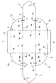
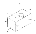
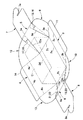
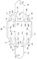
以下、本発明を、図面に示す各実施形態例に基づいて、さらに詳細に説明する。図1乃至図4は、直方体の食品包装箱に第1発明を適用した第1実施形態例を示すもので、図1は展開図、図2は箱に組み立てる途中の斜視図、図3は箱として組み立てられた状態の斜視図、図4は皿として組み立てられた状態の斜視図である。
【0008】
耐油・耐水加工を施した紙製の食品包装箱1は、長方形の底板2の対向する長片の一方の辺(図1において下側)に谷折り線2aを介して四角形の第1側板3を、他方の辺(図1において上側)に谷折り線2bを介して四角形の第2側板4をそれぞれ連設するとともに、対向する短辺の一方の辺(図1において右側)に谷折り線2cを介して四角形の第3側板5を、他方の辺(図1において左側)に谷折り線2dを介して四角形の第4側板6をそれぞれ連設し、さらに、第3側板5に谷折り線5aを介して蓋板7を、第4側板6に谷折り線6aを介して蓋板8をそれぞれ連設している。
【0009】
第1側板3は、隣接する第3側板5側に谷折り線3aを介して扇形の第1フラップ9を、隣接する第4側板6側に谷折り線3bを介して扇形の第2フラップ10を、残りの辺に谷折り線3cを介して折り曲げ片11をそれぞれ連設している。また、第2側板4は、隣接する第3側板5側に谷折り線4aを介して扇形の第3フラップ12を、隣接する第4側板6側に谷折り線4bを介して扇形の第4フラップ13を、残りの辺に谷折り線4cを介して折り曲げ片14をそれぞれ連設している。第1及び第3フラップ9,12は、展開状態で第3側板5との空間を埋める大きさに形成され、また、第2及び第4フラップ10,13も、同様に、展開状態で第4側板6との空間を埋める大きさに形成されている。
【0010】
第3側板5と第1フラップ9とは、それぞれの対向辺5b、9aに、互いに係合するための係合部として切り欠き15,16を対応する位置に形成し、また、第3側板5と第3フラップ12も、それぞれの対向辺5c,12aに互いに係合するための切り欠き17,18を対応する位置に形成している。同様に、第4側板6と第2フラップ10も、それぞれの対向辺6b,10aに互いに係合するための切り欠き19,20を、第4側板6と第4フラップ13も同様に、それぞれの対向辺6c,13aに互いに係合するための切り欠き21,22をそれぞれ対応する位置に形成している。蓋板7,8は、それぞれの先端に互いに係合するための係止溝7a,8aを設けている。
【0011】
この食品包装箱1は、各フラップ9,10,12,13をそれぞれ箱内側へ折り曲げ、第1側板3及び第2側板4を箱内側へ折り曲げ、続いて、第3側板5及び第4側板6を箱内側へ折り曲げると、フラップ9,12が第3側板5の内側に、フラップ10,13が第4側板6の内側にそれぞれ折り曲げられて、第1側板3、第2側板4、第3側板5及び第4側板6が底板2に対して90度立ち上がる。この状態で各側板3,4,5,6で囲まれる空間内に例えばケーキCを入れ、折り曲げ片11,14を箱内側へ折り曲げ、さらに蓋板7,8を箱内側へ折り曲げて、蓋板7,8の係止溝7a,8a同士を係合させると、食品包装箱1が直方体形の箱に組み立てられる。
【0012】
次に、食品包装箱1を皿として使用する順序を説明する。蓋板7,8の係合を解いて蓋板7,8を開き、第1側板3、第2側板4、第3側板5、第4側板6及び各フラップ9,10,12,13を広げて展開し、第3側板5の切り欠き15にフラップ9の切り欠き16を、第3側板5の切り欠き17にフラップ12の切り欠き18を、第4側板6の切り欠き19にフラップ10の切り欠き20を、第4側板6の切り欠き21にフラップ13の切り欠き22をそれぞれ差し込んで係合させると、第3側板5とフラップ9,12、第4側板6とフラップ10、13とがそれぞれ部分的に重なって、各側板3,4,5,6及び各フラップ9,10,12,13は、ケーキCを載置した底板2の周囲に斜め上方に立ち上り、底板2の周囲に上方へ広がるテーパー状の縁を形成して皿状に組み立てられる。
【0013】
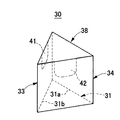
図5乃至図7は、平面視三角形の食品包装箱に第1発明を適用した第2実施形態例を示すもので、図5は展開図、図6は箱として組み立てられた状態の斜視図、図7は皿として組み立てられた状態の斜視図である。食品包装箱30は、三角形の底板31の各辺に、谷折り線31aを介して四角形の第1側板32を、谷折り線31bを介して四角形の第2側板33を、谷折り線31cを介して四角形の第3側板34をそれぞれ連設し、第1側板32の第2側板33側に谷折り線32aを介して第1フラップ35を連接し、第2側板33の第3側板34側に谷折り線33aを介して第2フラップ36を、第3側板34の第1側板32側に谷折り線34aを介して第3フラップ37をそれぞれ連設するとともに、第1側板32に谷折り線32bを介して三角形の蓋板38を連設している。各フラップ35,36,37は、展開状態で隣接する側板との間を埋める大きさに形成され、中央部分に谷折り線35b,36b,37bをそれぞれ設けている。
【0014】
また、第2側板33に谷折り線33bを介して折り曲げ片39を、第3側板34に谷折り線34bを介して折り曲げ片40をそれぞれ連設している。さらに、蓋板38の第2側板33に対応する辺38aに係止片41を、第3側板34に対応する辺38bに係止片42をそれぞれ折り曲げ可能に設け、第2側板33の折り線33bの中央に係止片41の挿入溝43を、第3側板34の折り線34bの中央に係止片43の挿入溝44をそれぞれ形成している。
【0015】
第1フラップ35と第2側板33とは、それぞれの対向辺35a,33cに互いに係合するための切り欠き45,46を、同様に、第2フラップ36と第3側板34も、それぞれの対向辺36a,34cに切り欠き47,48を、第3フラップ37と第1側板32も、それぞれの対向辺37a,32cに切り欠き49,50をそれぞれ対応する位置に形成している。
【0016】
この食品包装箱30は、各フラップ35,36,37を谷折り線35b,36b,37bにてそれぞれ二つに折り曲げた後、各フラップ35,36,37をそれぞれ箱内側へ折り曲げ、続いて、各側板32,33,34を箱内側へ折り曲げて、第1フラップ35を第2側板33の内側に、第2フラップ36を第3側板34の内側に、第3フラップ37を第1側板32の内側にそれぞれ寄せ、この状態で、各側板32,33,34で囲まれる空間内に食品を入れ、折り曲げ片39、40を箱内側へ折り曲げ、蓋板38を被せて、係止片41を挿入溝43に、係止片42を挿入溝44にそれぞれ挿入することにより、食品包装箱30が組み立てられる。
【0017】
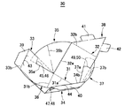
皿として使用する場合は、前記第1実施形態例と同様に、蓋板38を開けて各側板32,33,34及び各フラップ35,36,37を展開し、各フラップ35,36,37をそれぞれ広げて、第1フラップ35の切り欠き45を第2側板33の切り欠き46に、第2フラップ36の切り欠き47を第3側板34の切り欠き48に、第3フラップ37の切り欠き49を第1側板32の切り欠き50にそれぞれ係合させることにより、各側板33,33,34及び各フラップ35,36,37が底板31の周囲に斜め上方にに立ち上り、底板31の周囲に上方へ広がるテーパー状の縁を形成して皿状に組み立てられる。
【0018】
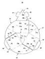
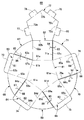
図8乃至図10は、平面視五角形の食品包装箱に第1発明を適用した第3実施形態例を示すもので、図8は展開図、図9は箱として組み立てられた状態の斜視図、図10は皿として組み立てられた状態の斜視図である。食品包装箱60は、五角形の底板61の各辺に、谷折り線61aを介して四角形の第1側板62を、谷折り線61bを介して四角形の第2側板63を、谷折り線61cを介して四角形の第3側板64を、谷折り線61dを介して四角形の第4側板65を、谷折り線61eを介して四角形の第5側板66をそれぞれ連設している。
【0019】
また、第1側板62の第2側板63側に谷折り線62aを介して第1フラップ67を、第2側板63の第3側板64側に谷折り線63aを介して第2フラップ68を、第3側板64の第4側板65側に谷折り線64aを介して第3フラップ69を、第4側板65の第5側板66側に谷折り線65aを介して第4フラップ70を、第5側板66の第1側板62側に谷折り線66aを介して第5フラップ71をそれぞれ連設するとともに、第1側板62に谷折り線62bを介して五角形の蓋板72を連設している。各フラップ67,68,69,70,71は、展開状態で隣接する側板との間を埋める大きさに形成されている。
【0020】
さらに、第2側板63に谷折り線63bを介して折り曲げ片73を、第3側板64に谷折り線64bを介して折り曲げ片74を、第4側板65に谷折り線65bを介して折り曲げ片75を、第5側板66に谷折り線66bを介して折り曲げ片76をそれぞれ連設している。また、蓋板72の第2側板63対応辺72aに係止片77を、第3側板64対応辺72bに係止片78を、第4側板65対応辺72cに係止片79を、第5側板66対応辺72dに係止片80をそれぞれ折り曲げ可能に設け、第2側板63の折り線63b中央に係止片73の挿入溝81を、第3側板64の折り線64b中央に係止片74の挿入溝82を、第4側板65の折り線65b中央に係止片75の挿入溝83を、第5側板66の折り線66b中央に係止片76の挿入溝84をそれぞれ形成している。
【0021】
第1フラップ67と第2側板63とは、それぞれの対向辺67a,63cに互いに係合するための切り欠き85,86を、同様に、第2フラップ68と第3側板64も、それぞれの対向辺68a,64cに切り欠き87,88を、第3フラップ69と第4側板65も、それぞれの対向辺69a,65cに切り欠き89,90を、第4フラップ70と第5側板66も、それぞれの対向辺70a,66cに切り欠き91,92を、第5フラップ71と第1側板62も、それぞれの対向辺71a,62cに切り欠き93,94をそれぞれ対応する位置に形成している。
【0022】
この食品包装箱60は、各フラップ67,68,69,70,71をそれぞれ箱内側へ折り曲げ、続いて、各側板62,63,64,65,66を箱内側へ折り曲げて底板61の周囲に90度立ち上げ、各側板62,63,64,65,66で囲まれる空間内に食品を入れ、折り曲げ片73,74,75,76をを箱内側へ折り曲げ、蓋板72を被せて、係止片77を挿入溝81に、係止片78を挿入溝82に、係止片79を挿入溝83に、係止片80を挿入溝84にそれぞれ挿入することにより、食品包装箱60が組み立てられる。
【0023】
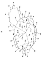
皿として使用する場合は、前記第1,2実施形態例と同様に、蓋板72を開けて各側板62,63,64,65,66及び各フラップ67,68,69,70,71を展開し、第1フラップ67の切り欠き85を第2側板63の切り欠き86に、第2フラップ68の切り欠き87を第3側板64の切り欠き88に、第3フラップ69の切り欠き89を第4側板65の切り欠き90に、第4フラップ70の切り欠き91を第5側板66の切り欠き92に、第5フラップ71の切り欠き93を第1側板62の切り欠き94にそれぞれ係合させることにより、各側板62,63,64,65,66及び各フラップ67,68,69,70,71が底板61の周囲に斜め上方に立ち上がり、底板61の周囲に上方へ広がるテーパー状の縁を形成して皿状に組み立てられる。
【0024】
なお、上記各実施形態例では、フラップと側板の係合部として、両者に切り欠きを設けたもので説明したが、例えば、側板に設けた差し込み孔にフラップの先端を挿入するものや、側板の対向辺に二段の切り欠きを設け、該二段の切り欠きにフラップの対向辺中間部を差し込んでもよい。
【0025】
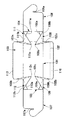
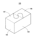
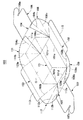
図11乃至図14は、蓋を開けると皿として使用可能な食品包装箱に第2発明を適用した第4実施形態例を示すもので、図11は展開図、図12は箱に組み立てる途中の平面図、図13は箱として組み立てられた状態の斜視図、図10は皿として使用される状態の斜視図である。食品包装箱100は、長方形の底板101の対向する長片の一方の辺に谷折り線101aを介して四角形の第1側板102を、他方の辺に谷折り線101bを介して四角形の第2側板103をそれぞれ連設するとともに、対向する短辺の一方の辺に谷折り線101cを介して四角形の第3側板104を、他方の辺に谷折り線101dを介して四角形の第4側板105をそれぞれ連設し、さらに、第3側板104に谷折り線104aを介して蓋板106を、第4側板105に谷折り線105aを介して蓋板107をそれぞれ連設している。蓋板106,107は、それぞれの先端に互いに係合するための係止溝106a,107aを設けている。
【0026】
第1側板102は、隣接する第3側板104側に谷折り線102aを介して扇形のフラップ108を、隣接する第4側板105側に谷折り線102bを介して扇形のフラップ109を、残りの辺に谷折り線102cを介して折り曲げ片110をそれぞれ連設している。また、第2側板103は、隣接する第3側板104側に谷折り線103aを介して扇形のフラップ111を、隣接する第4側板105側に谷折り線103bを介して扇形のフラップ112を、残りの辺に谷折り線103cを介して折り曲げ片113をそれぞれ連設している。
【0027】
フラップ108は、先端側となる第3側板104との対向辺108aを第3側板104の辺104bよりも内側に重ねて貼着され、同様に、フラップ111も、先端側となる第3側板104との対向辺111aを第3側板104の辺104cよりも内側に重ねて貼着されている。また、フラップ109も、先端側となる第4側板105との対向辺109aを第4側板105の辺105bよりも内側に重ねて貼着され、同様に、フラップ112も、先端側となる第4側板105との対向辺112aを第4側板105の辺105cよりも内側に重ねて貼着されている。これにより、各側板102,103,104,105及び各フラップ108,109,111,112は、底板101の周囲に斜め上方に立ち上がった状態となる。
【0028】
そして、フラップ108には、第3側板104の辺104bに沿って谷折り線108bが設けられるとともに、該谷折り線108bと第1側板102との谷折り線102aとの間に山折り線108cが設けられている。同様に、フラップ111にも、第3側板104の辺104cに沿って谷折り線111bが設けられるとともに、該谷折り線111bと第2側板103との谷折り線103aとの間に山折り線111cが設けられ、フラップ109も、第4側板105の辺105bに沿って谷折り線109bが設けられるとともに、該谷折り線109bと第1側板102との谷折り線102bとの間に山折り線109cが設けられ、フラップ112も、第4側板105の辺105cに沿って谷折り線112bが設けられるとともに、該谷折り線112bと第2側板103との谷折り線103bとの間に山折り線112cが設けられている。
【0029】
この食品包装箱100は、フラップ108を折り線108cにて山折りしながら、谷折り線102a及び谷折り線108bにて箱内側へ谷折りするとともに、残りの各フラップ109,111,112を山折り線109c,111c,112cにて山折りしながら、谷折り線102b及び谷折り線109b、谷折り線103a及び谷折り線111b、谷折り線103b及び谷折り線112bにて箱内側へ谷折りして、折り畳まれた各フラップ108,109,111,112を第3側板104及び第4側板105の内側に寄せていくと、第1側板102、第2側板103、第3側板104及び第4側板105が底板101の周囲に直角に立ち上がる。この状態で、各側板102,103,104,105で囲まれる空間内にケーキCを入れ、折り曲げ片110,113を箱内側へ折り曲げ、さらに蓋板106,107を箱内側へ折り曲げて、蓋板106,107の係止溝106a,107a同士を係合させると、食品包装箱100が直方体形の箱に組み立てられる。
【0030】
皿として使用する場合は、蓋板106,107の係合を解いて蓋板106,107を広げると、各側板102,103,104,105及び各フラップ108,109,111,112は、底板101の周囲に上方へ広がるテーパー状の縁を形成して皿状になる。
【0031】
なお、第4実施形態例では、平面視四角形の底板を有する食品包装箱で第2発明を説明したが、前記第2,3実施形態例のような平面視三角形、五角形の底板を有する食品包装箱にも第2発明は適用可能である。また、上記各実施形態例では、側板に蓋板を連接したもので説明したが、底板、側板及びフラップからなる箱に別体の蓋を用いてもよい。
【0032】
【発明の効果】
以上説明したように、本発明の食品包装箱は、展開が容易で、展開すると、底面に空隙がなくて内容物がこぼれない皿状にすることができる。したがって、別の皿を用意する必要がない。また、持ち運びやすく、収納された食品に手を触れずに皿にすることができるから衛生的である。さらに、底板、側板及びフラップの内側に絵を描くことにより、絵皿としての演出ができる。
【図面の簡単な説明】
【図1】第1実施形態例の箱の展開図
【図2】同じく箱に組み立てる途中の斜視図
【図3】同じく箱として組み立てられた状態の斜視図
【図4】同じく皿として組み立てられた状態の斜視図
【図5】第2実施形態例の箱の展開図
【図6】同じく箱として組み立てられた状態の斜視図
【図7】同じく皿として組み立てられた状態の斜視図
【図8】第3実施形態例の箱の展開図
【図9】同じく箱として組み立てられた状態の斜視図
【図10】同じく皿として組み立てられた状態の斜視図
【図11】第4実施形態例の箱の展開図
【図12】同じく箱に組み立てる途中の斜視図
【図13】同じく箱として組み立てられた状態の斜視図
【図14】同じく皿として組み立てられた状態の斜視図
【符号の説明】
1…食品包装箱、2…底板、2a,2b,2,c,2d…底板2の谷折り線、3…第1側板、3a…第1側板3の谷折り線、4…第2側板、4a…第2側板4の谷折り線、5…第3側板、5a…第3側板5の谷折り線、5b…第3側板5の第1フラップ9との対向辺、5c…第3側板5の第3フラップ9との対向辺、6…第4側板、6a…第4側板6の谷折り線、6b…第4側板6の第2フラップ10との対向辺、6c…第4側板6の第4フラップ13との対向辺、7,8…蓋板、9…第1フラップ、9a…第1フラップ9の第3側板5との対向辺、10…第2フラップ、10a…第2フラップ10の第4側板6との対向辺、12…第3フラップ、12a…第3フラップの第3側板5との対向辺、13…第4フラップ、13a…第4フラップの第4側板6との対向辺、15,16,17,18,19,20,21,22…切り欠き[0001]
TECHNICAL FIELD OF THE INVENTION
The present invention relates to a food packaging box that functions as a dish when the box is expanded.
[0002]
[Prior art]
As a food packaging box, a side plate is connected to each side of a square bottom plate in plan view via a valley fold line, and a flap that is bent to the inside of the other side plate on any one of the adjacent side plates is a valley fold line. An assembly box connected via a connector is often used. Also, for example, as a packaging box for cakes or the like, a plurality of side plates connected to each side of a square bottom plate via valley fold lines, and auxiliary pieces connected between the respective side plates via valley fold lines. And a lid plate continuously connected to the pair of side plates facing each other via the valley fold line, and a hanging piece continuously connected to the remaining pair of side plates via the fold line respectively. There is also one (for example, see Patent Document 1).
[0003]
[Patent Document 1]
JP-A-2000-318725 (
[0004]
[Problems to be solved by the invention]
However, although the above-mentioned conventional box has a function suitable for transportation and storage, the box becomes flat when the box is opened, so that the stored food needs to be transferred to another dish. For example, a single-box cake served as a dessert for school lunches was unsanitary because students took the cake and moved it to another plate to eat. In addition, when eating outdoors, since the user eats with a box, it is difficult to eat and the stored food may spill.
[0005]
Therefore, an object of the present invention is to provide a food packaging box which easily functions as a dish, which can be easily deployed, does not spill contents when deployed, and is easy to hold.
[0006]
[Means for Solving the Problems]
In order to achieve the above-mentioned object, the present invention provides a side plate on each side of a bottom plate of a polygon in plan view via a valley fold line, and the inside of the other side plate on any one of the adjacent side plates. In a food packaging box in which folded flaps are connected via a valley fold line, the first invention is characterized in that engaging portions are provided on opposite sides of the flap and the other side plate, respectively. According to a second aspect of the present invention, the tip side of the flap is overlapped and adhered to the other side plate, a valley fold line is provided on the flap along the other side plate, and the valley fold line and the valley fold on the continuous side are provided. A mountain fold line is provided between the line and the line. In these inventions, the lid may be separate or connected to one or two of the side plates. By drawing a picture on the inside of the bottom plate, the side plate and the flap, it is possible to produce a picture plate.
[0007]
BEST MODE FOR CARRYING OUT THE INVENTION
Hereinafter, the present invention will be described in more detail based on embodiments shown in the drawings. 1 to 4 show a first embodiment in which the first invention is applied to a rectangular parallelepiped food packaging box. FIG. 1 is an exploded view, FIG. 2 is a perspective view in the middle of assembling into a box, and FIG. FIG. 4 is a perspective view of a state where the plate is assembled as a dish.
[0008]
An oil- and water-resistant paper
[0009]
The
[0010]
The
[0011]
In this
[0012]
Next, the order in which the
[0013]
5 to 7 show a second embodiment in which the first invention is applied to a food packaging box having a triangular shape in a plan view. FIG. 5 is an exploded view, FIG. 6 is a perspective view of an assembled state as a box, FIG. 7 is a perspective view showing a state where the plate is assembled. The
[0014]
A
[0015]
The
[0016]
In this
[0017]
When used as a dish, as in the first embodiment, the
[0018]
8 to 10 show a third embodiment in which the first invention is applied to a food packaging box having a pentagonal shape in plan view. FIG. 8 is an exploded view, FIG. 9 is a perspective view of an assembled state as a box, FIG. 10 is a perspective view showing a state where the plate is assembled. The
[0019]
Further, the
[0020]
Further, a
[0021]
The
[0022]
In this
[0023]
When used as a dish, similarly to the first and second embodiments, the
[0024]
In each of the above embodiments, the notch is provided for both the flap and the side plate as the engaging portion. However, for example, the flap and the side plate may be inserted into the insertion hole provided in the side plate, or the side plate may be inserted. May be provided with two-step notches, and the middle of the opposing side of the flap may be inserted into the two-step notches.
[0025]
11 to 14 show a fourth embodiment in which the second invention is applied to a food packaging box that can be used as a dish when the lid is opened. FIG. 11 is an exploded view, and FIG. FIG. 13 is a plan view, FIG. 13 is a perspective view of a state assembled as a box, and FIG. 10 is a perspective view of a state used as a dish. The
[0026]
The
[0027]
The
[0028]
A
[0029]
In this
[0030]
When used as a dish, when the
[0031]
In the fourth embodiment, the second invention is described with the food packaging box having a bottom plate having a square shape in plan view, but the food packaging box having a triangular or pentagonal bottom plate in plan view as in the second and third embodiments is described. The second invention can be applied to a box. Further, in each of the above-described embodiments, the lid is connected to the side plate. However, a separate lid may be used for the box including the bottom plate, the side plate, and the flap.
[0032]
【The invention's effect】
As described above, the food packaging box of the present invention can be easily developed, and when deployed, can be formed into a dish shape having no gap on the bottom surface and preventing the contents from spilling. Therefore, there is no need to prepare another dish. In addition, it is easy to carry and can be made into a dish without touching the stored food, so that it is sanitary. Further, by drawing a picture on the inside of the bottom plate, the side plate and the flap, it is possible to produce a picture plate.
[Brief description of the drawings]
FIG. 1 is an exploded view of the box of the first embodiment example. FIG. 2 is a perspective view of the same box being assembled. FIG. 3 is a perspective view of the same box assembled. FIG. FIG. 5 is an exploded view of the box of the second embodiment example. FIG. 6 is a perspective view of the same assembled box. FIG. 7 is a perspective view of the same assembled dish. FIG. 9 is an exploded view of the box of the third embodiment. FIG. 9 is a perspective view of the same box assembled. FIG. 10 is a perspective view of the same box assembled. FIG. Exploded view [FIG. 12] Perspective view of the same assembling into a box [FIG. 13] Perspective view of the same assembling as a box [FIG. 14] Perspective view of same assembling as a plate [Description of reference numerals]
DESCRIPTION OF
Claims (4)
Priority Applications (1)
| Application Number | Priority Date | Filing Date | Title |
|---|---|---|---|
| JP2002332551A JP4457552B2 (en) | 2002-11-15 | 2002-11-15 | Food packaging box |
Applications Claiming Priority (1)
| Application Number | Priority Date | Filing Date | Title |
|---|---|---|---|
| JP2002332551A JP4457552B2 (en) | 2002-11-15 | 2002-11-15 | Food packaging box |
Related Child Applications (1)
| Application Number | Title | Priority Date | Filing Date |
|---|---|---|---|
| JP2009255854A Division JP4849168B2 (en) | 2009-11-09 | 2009-11-09 | Food packaging box |
Publications (2)
| Publication Number | Publication Date |
|---|---|
| JP2004168317A true JP2004168317A (en) | 2004-06-17 |
| JP4457552B2 JP4457552B2 (en) | 2010-04-28 |
Family
ID=32697546
Family Applications (1)
| Application Number | Title | Priority Date | Filing Date |
|---|---|---|---|
| JP2002332551A Expired - Fee Related JP4457552B2 (en) | 2002-11-15 | 2002-11-15 | Food packaging box |
Country Status (1)
| Country | Link |
|---|---|
| JP (1) | JP4457552B2 (en) |
Cited By (1)
| Publication number | Priority date | Publication date | Assignee | Title |
|---|---|---|---|---|
| JP2017007716A (en) * | 2015-06-24 | 2017-01-12 | エステー株式会社 | Air treatment agent container |
-
2002
- 2002-11-15 JP JP2002332551A patent/JP4457552B2/en not_active Expired - Fee Related
Cited By (1)
| Publication number | Priority date | Publication date | Assignee | Title |
|---|---|---|---|---|
| JP2017007716A (en) * | 2015-06-24 | 2017-01-12 | エステー株式会社 | Air treatment agent container |
Also Published As
| Publication number | Publication date |
|---|---|
| JP4457552B2 (en) | 2010-04-28 |
Similar Documents
| Publication | Publication Date | Title |
|---|---|---|
| CA2357297C (en) | Taco holder | |
| CA2336449C (en) | Food scoop with condiment holder | |
| US5118034A (en) | Food-accommodating container having multi-functional flaps | |
| US20020011514A1 (en) | Stackable food tray with condiment compartment | |
| KR20080063319A (en) | Containers and blanks for their manufacture | |
| US5979659A (en) | Sheets of corrugated paper for producing packings | |
| JP2004168317A (en) | Food packaging box | |
| US4260099A (en) | Expandable paperboard cup and blank therefor | |
| JP3633834B2 (en) | Packaging container | |
| JPH09169332A (en) | Carton | |
| JP2008265807A (en) | Packaging container | |
| JP4849168B2 (en) | Food packaging box | |
| JPH0748503Y2 (en) | Packaging tray | |
| JP2930938B1 (en) | Paper container | |
| GB2255075A (en) | Multi-purpose food carrying box | |
| JPH08256668A (en) | Vessel for food formation | |
| EP1567420A1 (en) | Reversibly collapsible/erectable container | |
| JP2004224345A (en) | Paper container with integrally formed cushioning structure | |
| JP3154489B2 (en) | Carton for multiple items | |
| TW458927B (en) | Carton for dispensing sheets | |
| JP3862804B2 (en) | Packaging box | |
| JP7196499B2 (en) | package | |
| JPH0411941Y2 (en) | ||
| JPH0712244Y2 (en) | Folding cup | |
| JP2024126195A (en) | container |
Legal Events
| Date | Code | Title | Description |
|---|---|---|---|
| A621 | Written request for application examination |
Free format text: JAPANESE INTERMEDIATE CODE: A621 Effective date: 20051031 |
|
| A977 | Report on retrieval |
Free format text: JAPANESE INTERMEDIATE CODE: A971007 Effective date: 20080527 |
|
| A131 | Notification of reasons for refusal |
Free format text: JAPANESE INTERMEDIATE CODE: A131 Effective date: 20080603 |
|
| A521 | Request for written amendment filed |
Free format text: JAPANESE INTERMEDIATE CODE: A523 Effective date: 20080725 |
|
| A131 | Notification of reasons for refusal |
Free format text: JAPANESE INTERMEDIATE CODE: A131 Effective date: 20090120 |
|
| A521 | Request for written amendment filed |
Free format text: JAPANESE INTERMEDIATE CODE: A523 Effective date: 20090316 |
|
| A131 | Notification of reasons for refusal |
Free format text: JAPANESE INTERMEDIATE CODE: A131 Effective date: 20090915 |
|
| A521 | Request for written amendment filed |
Free format text: JAPANESE INTERMEDIATE CODE: A523 Effective date: 20091109 |
|
| TRDD | Decision of grant or rejection written | ||
| A01 | Written decision to grant a patent or to grant a registration (utility model) |
Free format text: JAPANESE INTERMEDIATE CODE: A01 Effective date: 20100119 |
|
| A01 | Written decision to grant a patent or to grant a registration (utility model) |
Free format text: JAPANESE INTERMEDIATE CODE: A01 |
|
| A61 | First payment of annual fees (during grant procedure) |
Free format text: JAPANESE INTERMEDIATE CODE: A61 Effective date: 20100201 |
|
| R150 | Certificate of patent or registration of utility model |
Free format text: JAPANESE INTERMEDIATE CODE: R150 Ref document number: 4457552 Country of ref document: JP Free format text: JAPANESE INTERMEDIATE CODE: R150 |
|
| FPAY | Renewal fee payment (event date is renewal date of database) |
Free format text: PAYMENT UNTIL: 20130219 Year of fee payment: 3 |
|
| FPAY | Renewal fee payment (event date is renewal date of database) |
Free format text: PAYMENT UNTIL: 20130219 Year of fee payment: 3 |
|
| FPAY | Renewal fee payment (event date is renewal date of database) |
Free format text: PAYMENT UNTIL: 20130219 Year of fee payment: 3 |
|
| FPAY | Renewal fee payment (event date is renewal date of database) |
Free format text: PAYMENT UNTIL: 20140219 Year of fee payment: 4 |
|
| R250 | Receipt of annual fees |
Free format text: JAPANESE INTERMEDIATE CODE: R250 |
|
| R250 | Receipt of annual fees |
Free format text: JAPANESE INTERMEDIATE CODE: R250 |
|
| R250 | Receipt of annual fees |
Free format text: JAPANESE INTERMEDIATE CODE: R250 |
|
| R250 | Receipt of annual fees |
Free format text: JAPANESE INTERMEDIATE CODE: R250 |
|
| R250 | Receipt of annual fees |
Free format text: JAPANESE INTERMEDIATE CODE: R250 |
|
| R250 | Receipt of annual fees |
Free format text: JAPANESE INTERMEDIATE CODE: R250 |
|
| R250 | Receipt of annual fees |
Free format text: JAPANESE INTERMEDIATE CODE: R250 |
|
| R250 | Receipt of annual fees |
Free format text: JAPANESE INTERMEDIATE CODE: R250 |
|
| R250 | Receipt of annual fees |
Free format text: JAPANESE INTERMEDIATE CODE: R250 |
|
| LAPS | Cancellation because of no payment of annual fees |