【0001】
【発明の属する技術分野】
本発明は、ヘッドを往復移動させて該ヘッドからインクを液滴として吐出することによって記録媒体に画像を形成するシリアル式のインクジェットプリンタに関する。
【0002】
【従来の技術】
近年、インクジェット記録方式ではグラビア印刷方式より簡便・安価に画像を作成することができるため、写真・各種印刷・マーキング・カラーフィルターといった特殊印刷等の様々な印刷分野に応用されてきている。特に、インクジェット記録方式では、微細なドットを吐出・制御するインクジェット記録方式のインクジェットプリンタと、色再現域・耐久性・吐出適性等を改善したインクと、インク吸収性・色材発色性・表面光沢等を飛躍的に向上させた専用紙とを組み合わせることで、銀塩写真に匹敵する画質を得ることも可能となっている。
【0003】
インクジェット記録方式には、室温で固形のワックスインクを用いる相変化インクジェット方式、速乾性の有機溶剤を主体としたインクを用いるソルベント系インクジェット方式、紫外線の被照射により硬化する紫外線硬化型インクを用いるUVインク系インクジェット方式等がある。中でも、UVインク系ジェット方式は、他の記録方式に比べ比較的低臭気であり、専用紙以外にも速乾性・インク吸収性の無い記録媒体に記録できる点で注目されている。
【0004】
また、従来のインクジェットプリンタには、副走査方向に搬送されている記録媒体上において副走査方向に対して直交する主走査方向に複数並んだ吐出口からインクを吐出することにより画像記録を行うラインヘッド方式、主走査方向にヘッドを移動させてヘッドの移動中にヘッドの吐出口からインクを吐出することにより画像記録を行うシリアル方式がある。
【0005】
ラインヘッド方式であってもシリアル方式であっても紫外線硬化型インクを用いたインクジェットプリントでは、ラインヘッド又はヘッドより副走査方向の下流側において紫外線光源が主走査方向に配列されており、記録媒体が紫外線光源の下方を通過している時に紫外線光源からの紫外線を記録媒体上のインクに照射することでインクを硬化させる(例えば、特許文献1参照。)。また、シリアル方式のインクジェットプリンタでは、主走査方向に移動するキャリッジにヘッドが搭載されているが、このキャリッジに紫外線光源を搭載し、キャリッジとともにヘッドが主走査方向に移動している時に紫外線光源からの紫外線をインクに照射することでインクを硬化させることもある(例えば、特許文献2参照。)。
【0006】
【特許文献1】
特開2002−11860号公報(第10−11頁、第19図)
【特許文献2】
特開昭60−132767号公報
【0007】
【発明が解決しようとする課題】
しかし、ラインヘッド又はヘッドより下流側で紫外線光源が主走査方向に配列されているインクジェットプリンタでは、吐出口にインクが詰まることを防止するために、紫外線光源からの紫外線が吐出口に入射しないようにラインヘッド又はヘッドの周囲に紫外線遮蔽材を設ける必要がある。そのため、インクジェットプリンタの部品数が増えてしまい、またラインヘッド又はヘッドを清掃したりメンテナンスしたりする際に紫外線遮蔽材が邪魔となる。
【0008】
また、キャリッジに紫外線光源が搭載されているインクジェットプリンタでは、キャリッジとともにヘッド及び紫外線光源を移動させるためにより大きな駆動力を必要とし、駆動力が小さい場合にはキャリッジ、ヘッド、紫外線光源の移動速度及び加速度が低く、画像記録に要する時間が長い。また、キャリッジ、ヘッド、紫外線光源を支えるための剛性を大きくしなければならない。
そこで、本発明の目的は、ヘッドを支えるための剛性を小さくすることができ、ヘッドを移動させるための駆動力が小さくても短時間で画像記録を行え、更に、紫外線を遮蔽するための紫外線遮蔽材を必要としないインクジェットプリンタを提供することである。
【0009】
【課題を解決するための手段】
上記課題を解決するため、請求項1記載の発明のインクジェットプリンタは、
記録媒体を搬送する搬送機構と、
前記記録媒体上において前記記録媒体の搬送方向と直角な方向に往復移動し、光の被照射により硬化するインクを前記記録媒体に吐出するヘッドと、
前記ヘッドより前記搬送方向の下流側において前記搬送方向と直角な方向に光を前記記録媒体に対して走査する光走査機構と、
を備えることを特徴とする。
【0010】
請求項2に記載の発明は、請求項1に記載のインクジェットプリンタにおいて、前記光走査機構は、前記ヘッドの往復移動に同期して光を走査するように構成されたことを特徴とする。
【0011】
請求項1又は2に記載の発明では、搬送方向に直角な方向に移動するヘッドからインクが吐出され、吐出されたインクが記録媒体に着弾する。そして、記録媒体が搬送機構によって搬送方向の下流に搬送されると、光は記録媒体に対して光走査機構によって搬送方向に直角な方向に走査される。記録媒体に着弾したインクには、走査時に光が照射され、これによってインクが硬化する。この場合、往復移動するヘッドとは別に光走査機構がインクジェットプリンタに備わっているから、紫外線光源をヘッドと一体的に往復移動させずに済む。そのため、ヘッドを移動させるための駆動力が小さくてもヘッドを高速度で且つ高加速度で移動させることができるとともに、ヘッドを支えるための剛性を小さくすることができる。
【0012】
また、光走査機構がヘッドより搬送方向の下流側において光を走査しているから、光がヘッドに入射しない。そのため、ヘッドに光が入射することを遮蔽する遮蔽材インクジェットプリンタに設けなくても済み、インクジェットプリンタの部品数の削減を図ることができる。
【0013】
【発明の実施の形態】
以下に、図面を用いて本発明の具体的な態様について説明する。ただし、発明の範囲は、図示例に限定されない。
【0014】
図1は、本発明が適用されたシリアル方式のインクジェットプリンタ1を示した斜視図である。
図1に示されるように、インクジェットプリンタ1は、搬送方向である副走査方向Yに記録媒体100を搬送する搬送機構10と、搬送機構10によって搬送される記録媒体100を支持するプラテン20と、互いに平行となって副走査方向Yに対して直交する主走査方向Xに延在したガイド部材41,71と、ガイド部材41によって案内されて主走査方向Xに往復移動可能とされたキャリッジ30と、このキャリッジ30を主走査方向Xに移動させる駆動機構40と、キャリッジ30に取り付けられた複数のヘッド50,50,…と、キャリッジ30より副走査方向Yの下流側においてガイド部材71によって案内されて主走査方向Xに往復移動可能とされたキャリア60と、このキャリア60を主走査方向Xに移動させる駆動機構70と、キャリア60に取り付けられた二つの紫外線光源80,80と、を具備する。なお、以下の説明では、主走査方向X及び副走査方向Yの両方に直角な方向を上下方向として説明する。
【0015】
搬送機構10は、主走査方向Xに互いに平行となって延在するとともに主走査方向Xのそれぞれの軸心回りに回転自在な二つのローラ11,11と、これらローラ11,11を回転させるモータといった駆動機構と、を備える。記録媒体100は、ローラ11,11の回転によって搬送されるようになっている。
【0016】
本実施形態に用いられる記録媒体100としては、通常のインクジェットプリンタに適用される普通紙,再生紙,光沢紙等の各種紙,各種布地,各種不織布,樹脂,金属,ガラス等の材質からなる記録媒体が適用可能である。記録媒体100の形態としては、ロール状、カットシート状、板状等が適用可能である。本実施形態では、記録媒体100として、ロール状に巻かれた長尺な樹脂製フィルムを用いており、元巻きから繰り出された記録媒体100をローラ11,11にセッティングして用いる。
【0017】
特に、本実施形態で用いられる記録媒体100として、所謂軟包装に用いられる透明又は不透明な非吸収性の樹脂製フィルムが適用できる。樹脂製フィルムの具体的な樹脂の種類として、ポリエチレンテレフタレート,ポリエステル,ポリオレフィン,ポリアミド,ポリエステルアミド,ポリエーテル,ポリイミド,ポリアミドイミド,ポリスチレン,ポリカーボネート,ポリ−ρ−フェニレンスルフィド,ポリエーテルエステル,ポリ塩化ビニル,ポリ(メタ)アクリル酸エステル、ポリエチレン、ポリプロピレン、ナイロン等が適用可能であり、さらには、これら樹脂の共重合体、これら樹脂の混合物、これら樹脂を架橋したもの等も適用可能である。中でも、樹脂製フィルムの樹脂の種類として、延伸したポリエチレンテレフタレート,ポリスチレン,ポリプロピレン,ナイロンのいずれかを選択するのが、樹脂製フィルムの透明性・寸法安定性・剛性・環境負荷・コスト等の面で好ましく、2〜100μm(好ましくは6〜50μm)の厚みを有する樹脂製フィルムを用いるのが好ましい。また、樹脂製フィルムの支持体の表面にコロナ放電処理、易接着処理等の表面処理を施してもよい。さらに、本実施形態に用いられる記録媒体100として、樹脂により表面を被覆した各種紙,顔料を含むフィルム,発泡フィルム等の不透明な公知の記録媒体も適用可能である。
【0018】
プラテン20は、ローラ11とローラ11との間に配設され、二つのローラ11,11に対して平行な平坦面を有し、該平坦面で記録媒体100を下から支持するものである。
【0019】
プラテン20の上方において、ガイド部材41,71がインクジェットプリンタ1のフレームや筐体に固定されている。ガイド部材71は、ガイド部材41より副走査方向Yの下流側に配置されている。
【0020】
キャリッジ30は、ガイド部材41に対して主走査方向Xに摺動自在となって取り付けられており、キャリア60は、ガイド部材71に対して主走査方向Xに摺動自在となって取り付けられている。
【0021】
駆動機構40は、下方に指向した動力取出軸42aを有するモータ42と、動力取出軸42aと同軸となって動力取出軸42aに固定されたプーリー43と、プーリー43の軸と平行な軸回りに回転自在となったプーリー44と、プーリー43とプーリー44に環となって掛けられたベルト45と、を備える。上から下にプラテン20を見た場合、プーリー43とプーリー44の間には、プラテン20が配置されており、プーリー43とプーリー44を結ぶ線はガイド部材41と平行となっている。このベルト45の一部には、キャリッジ30が固定されている。
【0022】
複数のヘッド50,50,…は、主走査方向Xに列となってキャリッジ30に搭載され、プラテン20及び記録媒体100の上方においてキャリッジ30とともに主走査方向Xに移動可能とされる。それぞれのヘッド50においては、その下面に複数の吐出口が形成されており、複数の吐出口は副走査方向Yに列となって配列されている。各ヘッド50は、変形により内部のインクに圧力を付与するピエゾ素子、内部のインクを膜沸騰させることにより内部のインクに圧力を付与する加熱素子、その他内部のインクに圧力を付与する素子を吐出口ごとに有し、これら素子の動作により各吐出口から個別にインクを液滴として吐出するように構成されている。
【0023】
一つのヘッド50の各吐出口からは、数種の色のうちの何れかの色のインクが吐出される。ヘッド50ごとに異なる色のインクのインク滴が吐出されるが、同じ色のUVインクが二以上のヘッド50から吐出されても良い。本実施形態に用いられるインクの色は、イエロー(Y)、マゼンタ(M)、シアン(C)、ブラック(K)であり、図1において各ヘッド50に付された英字は吐出するインクの色を示している。YMCKの他に、ホワイト(W)、ライトイエロー(LY)、ライトマゼンタ(LM)、ライトシアン(LC)、ライトブラック(LK)等のインクを用いても良い。
【0024】
本実施形態に用いられるインクとしては、特に、「光硬化技術−樹脂・開始剤の選定と配合条件及び硬化度の測定・評価−(技術協会情報)」に記載の「光硬化システム(第4章)」の「光酸・塩基発生剤を利用する硬化システム(第1節)」、「光誘導型交互共重合(第2節)」等に適合するインクが適用可能であり、通常のラジカル重合により硬化するものであってもよい。
【0025】
具体的に、本実施形態に用いられるインクは、光としての紫外線の被照射により硬化する性質を有する紫外線硬化型インクであり、主成分として、重合性化合物(公知の重合性化合物を含む。)と、光開始剤と、色材とを少なくとも含むものである。ただし、本実施形態に用いるインクとして、上記「光誘導型交互共重合(第2節)」に適合するインクを用いる場合には、光開始剤は除外されてもよい。
【0026】
紫外線硬化型インクは、重合性化合物として、ラジカル重合性化合物を含むラジカル重合系インクとカチオン重合性化合物を含むカチオン重合系インクとに大別されるが、その両系のインクが本実施形態に用いられるインクとしてそれぞれ適用可能であり、ラジカル重合系インクとカチオン重合系インクとを複合させたハイブリッド型インクを本実施形態に用いられるインクとして適用してもよい。
【0027】
酸素による重合反応の阻害が少ない又は無いカチオン重合系インクのほうが機能性・汎用性に優れるため、本実施形態では、特に、カチオン重合系インクを用いている。
【0028】
本実施形態に用いられるカチオン重合系インクは、具体的に、オキセタン化合物,エポキシ化合物,ビニルエーテル化合物等といったカチオン重合性化合物と、光カチオン開始剤と、色材とを少なくとも含む混合物であり、上記の通り、紫外線の被照射により硬化する性質を有するものである。
【0029】
ところで、本実施形態に用いられるインク(ラジカル重合系インク,カチオン重合系インク及びハイブリッド型インクを含む。)は、上記の通り、紫外線の被照射により硬化するものであるが、必ずしもこれには限定されず、紫外線以外の光の被照射により硬化するものであってもよい。ここでいう「光」とは、広義の光であって、紫外線、電子線、X線、可視光線、赤外線等の電磁波を含むものである。つまり、本実施形態に用いられるインクには、紫外線以外の光で重合して硬化する重合性化合物と、紫外線以外の光で重合性化合物同士の重合反応を開始させる光開始剤とが適用されてもよい。
【0030】
駆動機構70も駆動機構40と同様に、モータ42と、プーリー43と、プーリー44と、ベルト45と、を備えるが、駆動機構70のベルト45の一部は、キャリッジ30に固定されているのではなく、キャリア60に固定されている。
【0031】
紫外線光源80は、キャリア60に取り付けられており、記録媒体100に向けて紫外線を照射するものである。紫外線光源80として、LED(light emitting diode)、蛍光灯、高圧水銀ランプ、メタルハライドランプ、高圧水銀スポットランプ、キセノンランプ等が適用可能である。紫外線光源80を上方から覆う遮光機構(例えば、ひさし、かさ等)をキャリア60に設けて、紫外線光源80から発した紫外線が一方向に向かって照射し他方向に照射しない遮光機構によって防止しても良い。紫外線以外の光で硬化する光硬化型のインクを用いる場合には、紫外線光源80に代えて、その光を照射する光源をキャリア60に取り付けなければならない。
以上の構成において、光を記録媒体100に対して走査する光走査機構は、キャリア60、ガイド部材71、駆動機構70、紫外線光源80からなる。
【0032】
次に、インクジェットプリンタ1の動作について説明する。
作業者が記録媒体100をローラ11,11に掛けて、インクジェットプリンタ1の電源をオン状態とすると、紫外線光源80,80は、発光して、インク滴が着弾される記録媒体100に向けて紫外線を照射する。
【0033】
紫外線光源80,80が発光している状態で、搬送機構10において、駆動機構がローラ11,11を回転させると、ローラ11,11の回転に伴い記録媒体100が副走査方向Yに搬送される。ここで、駆動機構がローラ11,11を所定角度ずつ回転させることで、搬送及び搬送停止が順に繰り返され、記録媒体100が間欠的に搬送される。
【0034】
間欠的搬送における停止中に駆動機構40のモータ42が等速度で回転することによって、モータ42の動力がベルト45を通じてキャリッジ30に伝達し、キャリッジ30が等速で主走査方向Xに往動し、復動し又は往復移動する。キャリッジ30の移動に伴ってヘッド50,50,…もキャリッジ30と一体となって移動するが、ヘッド50,50,…は移動中に各吐出口から記録媒体100に向けてインクを液滴として吐出し、インクの液滴が、停止している記録媒体100に着弾する。
【0035】
一方、キャリッジ30の移動中に駆動機構70のモータ42も等速度で回転することによって、モータ42の動力がベルト45を通じてキャリア60に伝達し、キャリア60が等速で主走査方向に往動し、復動し又は往復移動する。キャリッジ30及びキャリア60の移動中において、キャリア60の移動速度がキャリッジ30の移動速度と同じとなるように、駆動機構40のモータ42の回転速度と駆動機構70のモータ42の回転速度が設定されており、更に、副走査方向Yにキャリア60を見た場合にキャリア60がキャリッジ30と同期するように、駆動機構40のモータ42の位相と駆動機構70のモータ42の位相が設定されている。従って、紫外線光源80,80がヘッド50,50,…に同期して主走査方向Xに移動し、紫外線の走査がヘッド50,50,…の移動に同期する。
【0036】
キャリア60の移動に伴って紫外線光源80,80もキャリア60と一体となって移動し、紫外線光源80,80の移動によって紫外線が記録媒体100に対して走査される。記録媒体100に着弾したインクは、紫外線光源80,80から紫外線が照射されることによって硬化する。
【0037】
間欠的搬送においてローラ11,11が回転している時には、駆動機構40,70それぞれのモータ42が停止しており、キャリッジ30及びキャリア60は主走査方向Xの移動範囲の一方の端に停止している。
【0038】
以上のように、紫外線光源80,80の発光中に搬送機構10が記録媒体100を間欠的に搬送するとともにキャリッジ30及びキャリア60の往復移動が繰り返され、キャリッジ30の移動中にヘッド50,50,が適宜インク滴を吐出することによって、記録媒体100上に画像が形成される。
【0039】
なお、ヘッド50,50,…が、キャリッジ30の往動中のみ又は復動中のみにインクを吐出するものとしても良い。キャリッジ30の往動中のみにヘッド50,50,…がインクを吐出する場合には、記録媒体100の間欠的搬送が停止している時にキャリッジ30が復動し、キャリッジ30の復動中のみにヘッド50がインクを吐出する場合には、記録媒体100の間欠的搬送が停止している時にキャリッジ30が往動する。このような場合においても、キャリア60は、キャリッジ30に同期して移動するのは勿論である。
【0040】
以上のように本実施形態においては、ヘッド50,50,…を搭載したキャリッジ30とは別にキャリア60が設けられ、このキャリア60に紫外線光源80,80が搭載されているから、キャリッジ30に紫外線光源を搭載しなくても済む。従って、ヘッドの搭載されたキャリッジに紫外線光源が搭載された従来のインクジェットプリンタに比較しても、キャリッジ30及びガイド部材41にかかる重さが少なくなり、キャリッジ30及びガイド部材41の剛性を小さくすることができる。
【0041】
また、キャリッジ30に紫外線光源が搭載されていないから、紫外線光源を搭載した場合と比較して、キャリッジ30の加速度領域を減少することができる。また、キャリッジ30の軽量化に応じて駆動機構40のモータ42を小さくすることができ、駆動機構40のモータ42の小型化が可能となる。従って、記録媒体100に画像形成するために要する時間を短縮することができる。また、ヘッド50,50,…の搭載されたキャリッジに紫外線光源が搭載されていないから、ヘッド50,50,…の周囲の構成が簡素化して、ヘッド50,50,…のメンテナンスを行いやすくなる。
【0042】
また、キャリア60とともに紫外線光源80,80が主走査方向Xに移動するため、ラインヘッドやヘッドの下流側に紫外線光源が配列されている従来のインクジェットプリンタに比較しても、紫外線光源の数又はエネルギー容量を少なくすることができ、紫外線照射に要する電力を最小限に抑えることができる。また、紫外線光源80,80がヘッド50,50,…より副走査方向Yの下流側で移動するため、紫外線光源80,80からの紫外線がヘッド50,50,…に入射し難い。そのため、ヘッド50,50,…に対しての紫外線入射を遮蔽する紫外線遮蔽材をキャリア60等に設けなくても済み、インクジェットプリンタ1の部品数の削減を図ることができる。
【0043】
なお、キャリッジ30とキャリア60の間に、紫外線光源80,80から発した光を遮蔽することによってキャリア60のヘッド50,50,…に光が入射することを防止する直接光防止機構(例えば、記録媒体100上であってキャリッジ30とキャリア60の間に配設されるとともに、主走査方向Xに延在した仕切り部材)を設けても良いし、紫外線光源80,80から発した光の反射を抑制することによって乱反射による光がキャリア60のヘッド50,50,…に入射することを防止する光源反射防止機構(例えば、前記仕切り部材の表面に形成されるとともに、紫外線光源80,80から発した光に対して低反射率な膜)を設けても良い。また、記録媒体100で反射した光をヘッド50,50,…に入射することを防止するための反射光防止機構(例えば、ヘッド50から吐出されるインクの軌道を除いてヘッド50を下から覆う被覆材)を設けても良い。
【0044】
〔第二の実施の形態〕
第二実施形態のインクジェットプリンタについて説明する。図2は、第二実施形態のインクジェットプリンタ101を示した正面図である。このインクジェットプリンタ101も、図1に示されたインクジェットプリンタ1と同様に、搬送機構10と、プラテン20と、キャリッジ30と、駆動機構40と、ガイド部材41と、ヘッド50,50,…と、を備える。図2において、搬送機構10のローラ11,11の図示を省略している。インクジェットプリンタ101については、図1に示されたインクジェットプリンタ1と同様の構成要素に同様の符号を付し、以下では異なる構成について主に説明する。
【0045】
インクジェットプリンタ101は、図1のインクジェットプリンタ1のキャリア60、駆動機構70、ガイド部材71及び紫外線光源80,80の代わりに、キャリッジ30より副走査方向Yの下流側において記録媒体100に対する照射領域をキャリッジ30の移動に追従させることによって紫外線ビーム120を記録媒体100に対して走査する光走査機構110を具備する。
【0046】
光走査機構110は、紫外線を発する紫外線光源111と、紫外線光源111から発散した紫外線を集光することで平行光線の紫外線ビーム120を出射するコリメータレンズ112と、コリメータレンズ112で出射した紫外線ビーム120を一方向に集束して出射するシリンドリカルレンズ113と、複数の鏡面を有するとともにシリンドリカルレンズ113から出射された紫外線ビーム120をそれぞれの鏡面で偏向するポリゴンミラー114と、ポリゴンミラー114を矢印R回りに等速度回転させるモータといった駆動機構(図示略)と、ポリゴンミラー114から入射した紫外線ビーム120を記録媒体100へ出射するfθレンズ115と、を備える。fθレンズ115は、ポリゴンミラー114の等速度運動によって主走査方向Xに紫外線ビーム120を等速走査できる特性となっている。
【0047】
また、このインクジェットプリンタ101は、記録媒体100に対して画像を形成する時に紫外線ビーム120による照射をオンするとともに画像を形成しない時に紫外線ビーム120による照射をオフする切替手段を備える。切替手段としては、遮蔽部材によって紫外線ビーム120の光路を遮蔽したり開放したりするメカニカルシャッタ機構、紫外線ビーム120の波長を変調させることによってインクが硬化する波長とインクが硬化しない波長に切り替える音響光学変調器(AOM:Acousto−Optic Modulator)、紫外線光源11の電源をオン/オフするスイッチング素子を挙げることができる。スイッチング素子によって紫外線光源11の電源をオン/オフすれば、紫外線光源11の耐用期間が延びる。
【0048】
次に、インクジェットプリンタ101の動作について説明する。
作業者が記録媒体100をローラ11,11に掛けて、インクジェットプリンタ101の電源をオン状態とすると、紫外線光源111が発光する。
【0049】
紫外線光源111が発光している状態で、搬送機構10が記録媒体100を間欠的に搬送する。間欠的搬送における停止中に駆動機構40のモータ42が等速度で回転することによって、キャリッジ30が等速で主走査方向Xに往動する。ヘッド50,50,…は往動中に各吐出口からインクを液滴として吐出する。
【0050】
一方、キャリッジ30の往動中に、光走査機構110のモータがポリゴンミラー114を等速度で回転させることによって、ポリゴンミラー114の或る面で偏向した紫外線ビーム120が主走査方向Xに照射されていく。これによって、紫外線ビーム120が記録媒体100に対して主走査方向Xに走査される。記録媒体100に着弾したインクは、紫外線ビーム120に照射されることによって硬化する。
【0051】
ここで、紫外線ビーム120が主走査方向Xに照射されていく速度が、キャリッジ30の移動速度と同じとなるように、駆動機構40のモータ42の回転速度と光走査機構110のモータの回転速度が設定されており、更に、副走査方向Yにキャリッジ30を見た場合にキャリッジ30の位置が紫外線ビーム120の照射位置の上方となるように、駆動機構40のモータ42の位相と光走査機構110のモータの位相が設定されている。従って、紫外線ビーム120は、ヘッド50,50,…の移動に同期して走査される。
【0052】
間欠的搬送において記録媒体100が搬送されている時に、駆動機構40のモータ42が反対に回転することによってキャリッジ30は主走査方向Xに復動し、光走査機構110のモータが停止してポリゴンミラー114の回転が停止する。ポリゴンミラー114が停止している時には、上記切替手段が紫外線ビーム120による照射をオフしている。
【0053】
以上のように、紫外線光源111の発光中に搬送機構10が記録媒体100を間欠的に搬送するとともにキャリッジ30の往復移動が繰り返され、更に光走査機構110がキャリッジ30の往動に同期して紫外線ビーム120を記録媒体100に対して走査し、キャリッジ30の移動中にヘッド50,50,…が適宜インク滴を吐出することによって、記録媒体100上に画像が形成される。
【0054】
光走査機構110による紫外線ビーム120の走査方向は一方向であり、キャリッジ30が復動している時には、ヘッド50,50,…からインクが吐出されない。画像形成に要する時間が多くなるが、キャリッジ30が復動している最中に記録媒体100に着弾したインクが確実に硬化し、次にキャリッジ30が往動してヘッド50,50,から吐出されたインクが、前に記録媒体100に着弾したインクに混ざらない。そのため、高画質な画像を形成することができる。
【0055】
以上のように本実施形態においては、光走査機構110がヘッド50,50,…より副走査方向Yの下流側において記録媒体100に対して紫外線ビーム120を走査しているから、キャリッジ30に紫外線光源を搭載しなくても済む。従って、第一実施形態のインクジェットプリンタ1と同様に、キャリッジ30及びガイド部材41の剛性を小さくすることができ、モータ42の小さい駆動力でもキャリア60の移動速度及びキャリア60が等速になるまでの加速度が紫外線光源の重み分だけ大きくすることができる。また、紫外線照射に要する電力及び紫外線光源を最小限に抑えることができ、ヘッド50,50,…に対しての紫外線入射を遮蔽する紫外線遮蔽材をキャリア60等に設けなくても済む。
【0056】
〔第三の実施の形態〕
第三実施形態のインクジェットプリンタについて説明する。図3は、第三実施形態のインクジェットプリンタ201を示した正面図である。このインクジェットプリンタ201も、図2に示されたインクジェットプリンタ101と同様に、搬送機構10と、プラテン20と、キャリッジ30と、駆動機構40と、ヘッド50,50,…と、を備え、更に、インクジェットプリンタ101の光走査機構110とは別の光走査機構210を備える。第二実施形態のインクジェットプリンタ101では、光走査機構110がポリゴンミラー式の光走査機構であったのに対して、第三実施形態のインクジェットプリンタ201では、光走査機構210がガルバノミラー式の光走査機構である。インクジェットプリンタ201については、図2に示されたインクジェットプリンタ101と同様の構成要素に同様の符号を付し、以下では異なる構成について主に説明する。また、図3において、搬送機構10のローラ11,11の図示を省略している。
【0057】
光走査機構210は、図1に示された光走査機構110と同様に、紫外線光源111と、コリメータレンズ112と、シリンドリカルレンズ113と、を備える。更に、光走査機構210は、鏡面214aを有するとともにシリンドリカルレンズ113から出射された紫外線ビーム120を鏡面214aで偏向するガルバノミラー214と、ガルバノミラー214を所定角度の範囲で往復回動させるモータといった駆動機構(図示略)と、ガルバノミラー214から入射した紫外線ビーム120を記録媒体100へ出射するfθレンズ215と、を備える。このfθレンズ215は、ガルバノミラー214が一方向に回転している時に主走査方向Xに紫外線ビーム120の等速走査できる特性となっている。
【0058】
また、このインクジェットプリンタ201は、第二実施形態のインクジェットプリンタ1と同様に、記録媒体100に対して画像を形成する時に紫外線ビーム120による照射をオンするとともに画像を形成しない時に紫外線ビーム120による照射をオフする切替手段を備える。
【0059】
次に、インクジェットプリンタ201の動作について説明する。
作業者が記録媒体100をローラ11,11に掛けて、インクジェットプリンタ201の電源をオン状態とすると、紫外線光源111が発光する。
【0060】
紫外線光源111が発光している状態で、搬送機構10が記録媒体100を間欠的に搬送する。間欠的搬送における停止中に駆動機構40のモータ42が等速度で回転することによって、キャリッジ30が等速で主走査方向Xに往動し、復動し又は往復移動する。ヘッド50,50,…は移動中に各吐出口からインクを液滴として吐出する。
【0061】
一方、キャリッジ30の移動中に、光走査機構210のモータがガルバノミラー214を回動させることによって、ガルバノミラー214の鏡面214aで偏向した紫外線ビーム120が主走査方向Xに照射されていく。これによって、紫外線ビーム120が記録媒体100に対して主走査方向Xに走査される。記録媒体100に着弾したインクは、紫外線ビーム120に照射されることによって硬化する。
【0062】
ここで、紫外線ビーム120が主走査方向Xに照射されていく速度が、キャリッジ30の移動速度と同じとなるように、駆動機構40のモータ42の回転速度と光走査機構210のモータの回転速度が設定されており、更に、副走査方向Yにキャリッジ30を見た場合にキャリッジ30の位置が紫外線ビーム120の照射位置の上方となるように、駆動機構40のモータ42の位相と光走査機構210のモータの位相が設定されている。従って、紫外線ビーム120は、ヘッド50,50,…に同期して主走査方向Xに走査される。
【0063】
間欠的搬送において記録媒体100が搬送されている時には、駆動機構40のモータ42及び光走査機構210のモータが停止しており、キャリッジ30が主走査方向Xの移動範囲の一方の端に停止しているとともに、ガルバノミラー214による走査も停止している。
【0064】
以上のように、紫外線光源111の発光中に搬送機構10が記録媒体100を間欠的に搬送するとともにキャリッジ30の往復移動が繰り返され、更にガルバノミラー214の往復回動が繰り返され、キャリッジ30の移動中にヘッド50,50,が適宜インク滴を吐出することによって、記録媒体100上に画像が形成される。
【0065】
なお、光走査機構210による走査方向は双方向であり、キャリッジ30が往動している時でも復動している時でもヘッド50,50,…からインクが吐出される場合には、画像形成に要する時間が短くなる。キャリッジ30の往復移動中にヘッド50,50,…からインクが吐出される場合は、キャリッジ30が往動している時のみ、又はキャリッジ30が復動している時のみに、ヘッド50,50,…からインクが吐出される場合に比較して、画像の画質が低い。
【0066】
本実施形態のインクジェットプリンタ201においても、光走査機構210がヘッド50,50,…より副走査方向Yの下流側において紫外線ビーム120を記録媒体100に対して走査しているから、第二実施形態のインクジェットプリンタ101と同様の効果を奏する。
【0067】
【発明の効果】
本発明によれば、往復移動するヘッドとは別に光走査機構がインクジェットプリンタに備わっているから、ヘッドを移動させるための駆動力が小さくてもヘッドを高速度で且つ高加速度で移動させることができるとともに、ヘッドを支えるための剛性を小さくすることができる。また、ヘッドに光が入射することを遮蔽する遮蔽材インクジェットプリンタに設けなくても済み、インクジェットプリンタの部品数の削減を図ることができる。
【図面の簡単な説明】
【図1】本発明が適用されたインクジェットプリンタを示した斜視図である。
【図2】図1のインクジェットプリンタとは別のインクジェットプリンタを示した正面図である。
【図3】図1、図2のインクジェットプリンタとは別のインクジェットプリンタを示した正面図である。
【符号の説明】
1、101、201 インクジェットプリンタ
50 ヘッド
60 キャリア
70 駆動機構
80 紫外線光源
110、210 光走査機構[0001]
TECHNICAL FIELD OF THE INVENTION
The present invention relates to a serial-type inkjet printer that forms an image on a recording medium by reciprocating a head and ejecting ink as droplets from the head.
[0002]
[Prior art]
In recent years, since the inkjet recording method can create an image more easily and at lower cost than the gravure printing method, it has been applied to various printing fields such as photographs, various printings, special printings such as marking and color filters. In particular, in the ink jet recording method, an ink jet printer of the ink jet recording method that discharges and controls fine dots, ink with improved color reproduction area, durability, discharge suitability, etc., ink absorption, coloring material color development, surface gloss By combining it with special paper with a dramatic improvement in image quality, it is possible to obtain image quality comparable to silver halide photography.
[0003]
Ink jet recording methods include a phase change ink jet method using a wax ink that is solid at room temperature, a solvent ink jet method that uses an ink mainly composed of a quick-drying organic solvent, and a UV that uses an ultraviolet-curable ink that cures when irradiated with ultraviolet light. There are ink-based inkjet systems and the like. Above all, the UV ink jet method has attracted attention because it has a relatively low odor compared to other recording methods and can be printed on a recording medium other than specialty paper, which has no quick drying property and no ink absorption.
[0004]
Further, in a conventional inkjet printer, a line for performing image recording by discharging ink from a plurality of discharge ports arranged in a main scanning direction orthogonal to the sub-scanning direction on a recording medium conveyed in the sub-scanning direction. There is a head method, and a serial method in which an image is recorded by moving the head in the main scanning direction and ejecting ink from ejection ports of the head while the head is moving.
[0005]
In ink-jet printing using an ultraviolet curable ink, whether a line head system or a serial system, an ultraviolet light source is arranged in the main scanning direction on the downstream side of the line head or the head in the sub scanning direction. The ink is cured by irradiating the ink on the recording medium with the ultraviolet light from the ultraviolet light source while the light passes below the ultraviolet light source (for example, see Patent Document 1). In a serial inkjet printer, a head is mounted on a carriage that moves in the main scanning direction.An ultraviolet light source is mounted on this carriage, and when the head moves with the carriage in the main scanning direction, the head is mounted on the carriage. The ink may be cured by irradiating the ink with ultraviolet rays (for example, see Patent Document 2).
[0006]
[Patent Document 1]
JP-A-2002-11860 (pages 10-11, FIG. 19)
[Patent Document 2]
JP-A-60-132767
[0007]
[Problems to be solved by the invention]
However, in an inkjet printer in which the ultraviolet light sources are arranged in the main scanning direction on the downstream side of the line head or the head, in order to prevent the ink from being clogged in the discharge ports, the ultraviolet light from the ultraviolet light source is prevented from entering the discharge ports. It is necessary to provide a line head or an ultraviolet shielding material around the head. For this reason, the number of parts of the ink jet printer increases, and the ultraviolet shielding material hinders the cleaning or maintenance of the line head or the head.
[0008]
In addition, in an ink jet printer in which an ultraviolet light source is mounted on a carriage, a larger driving force is required to move the head and the ultraviolet light source together with the carriage, and when the driving force is small, the moving speed of the carriage, the head, and the ultraviolet light source are increased. The acceleration is low and the time required for image recording is long. Also, the rigidity for supporting the carriage, head, and ultraviolet light source must be increased.
Therefore, an object of the present invention is to reduce the rigidity for supporting the head, perform image recording in a short time even if the driving force for moving the head is small, and further use the ultraviolet light for shielding the ultraviolet light. An object of the present invention is to provide an ink jet printer that does not require a shielding material.
[0009]
[Means for Solving the Problems]
In order to solve the above-mentioned problems, an inkjet printer according to the first aspect of the present invention includes:
A transport mechanism for transporting the recording medium;
A head that reciprocates on the recording medium in a direction perpendicular to the transport direction of the recording medium, and discharges ink that is cured by being irradiated with light to the recording medium,
An optical scanning mechanism that scans the recording medium with light in a direction perpendicular to the transport direction on the downstream side of the transport direction from the head,
It is characterized by having.
[0010]
According to a second aspect of the present invention, in the inkjet printer according to the first aspect, the optical scanning mechanism is configured to scan light in synchronization with the reciprocating movement of the head.
[0011]
According to the first or second aspect of the invention, ink is ejected from the head moving in a direction perpendicular to the transport direction, and the ejected ink lands on the recording medium. Then, when the recording medium is transported downstream in the transport direction by the transport mechanism, the light is scanned on the recording medium in a direction perpendicular to the transport direction by the optical scanning mechanism. The ink that has landed on the recording medium is irradiated with light during scanning, whereby the ink is cured. In this case, since the inkjet printer is provided with an optical scanning mechanism separately from the reciprocating head, the ultraviolet light source does not have to be reciprocated integrally with the head. Therefore, even if the driving force for moving the head is small, the head can be moved at high speed and high acceleration, and the rigidity for supporting the head can be reduced.
[0012]
Further, since the optical scanning mechanism scans the light downstream of the head in the transport direction, the light does not enter the head. Therefore, it is not necessary to provide a shielding material for the ink jet printer that blocks light from entering the head, and the number of components of the ink jet printer can be reduced.
[0013]
BEST MODE FOR CARRYING OUT THE INVENTION
Hereinafter, specific embodiments of the present invention will be described with reference to the drawings. However, the scope of the invention is not limited to the illustrated example.
[0014]
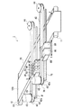
FIG. 1 is a perspective view showing a serial type inkjet printer 1 to which the present invention is applied.
As illustrated in FIG. 1, the inkjet printer 1 includes a transport mechanism 10 that transports the recording medium 100 in a sub-scanning direction Y that is a transport direction, a platen 20 that supports the recording medium 100 transported by the transport mechanism 10, Guide members 41 and 71 which are parallel to each other and extend in a main scanning direction X orthogonal to the sub-scanning direction Y; a carriage 30 guided by the guide members 41 and capable of reciprocating in the main scanning direction X; , A driving mechanism 40 for moving the carriage 30 in the main scanning direction X, a plurality of heads 50 attached to the carriage 30, and a guide member 71 on the downstream side of the carriage 30 in the sub scanning direction Y. And a driving mechanism 70 for moving the carrier 60 in the main scanning direction X. Comprises the two UV light sources 80, 80 attached to the carrier 60. In the following description, a direction perpendicular to both the main scanning direction X and the sub-scanning direction Y will be described as a vertical direction.
[0015]
The transport mechanism 10 includes two rollers 11, 11 extending parallel to each other in the main scanning direction X and rotatable around respective axes in the main scanning direction X, and a motor for rotating these rollers 11, 11. And a driving mechanism. The recording medium 100 is transported by the rotation of the rollers 11,11.
[0016]
As the recording medium 100 used in the present embodiment, various kinds of paper such as plain paper, recycled paper, glossy paper, and the like, various fabrics, various nonwoven fabrics, resins, metals, glass, and other materials applicable to ordinary inkjet printers are used. The medium is applicable. As a form of the recording medium 100, a roll shape, a cut sheet shape, a plate shape, or the like can be applied. In this embodiment, a long resin film wound in a roll shape is used as the recording medium 100, and the recording medium 100 unwound from the original winding is set on the rollers 11 and used.
[0017]
In particular, as the recording medium 100 used in the present embodiment, a transparent or opaque non-absorbable resin film used for so-called soft packaging can be applied. Specific types of resin for the resin film include polyethylene terephthalate, polyester, polyolefin, polyamide, polyesteramide, polyether, polyimide, polyamideimide, polystyrene, polycarbonate, poly-ρ-phenylene sulfide, polyetherester, and polyvinyl chloride. , Poly (meth) acrylate, polyethylene, polypropylene, nylon and the like are applicable, and furthermore, copolymers of these resins, mixtures of these resins, and those obtained by crosslinking these resins are also applicable. Among them, the choice of stretched polyethylene terephthalate, polystyrene, polypropylene, or nylon as the type of resin for the resin film depends on the transparency, dimensional stability, rigidity, environmental load, cost, etc. of the resin film. It is preferable to use a resin film having a thickness of 2 to 100 μm (preferably 6 to 50 μm). Further, the surface of the resin film support may be subjected to a surface treatment such as a corona discharge treatment and an easy adhesion treatment. Further, as the recording medium 100 used in the present embodiment, known opaque recording media such as various kinds of paper coated on the surface with a resin, a film containing a pigment, and a foamed film can be applied.
[0018]
The platen 20 is disposed between the rollers 11, has a flat surface parallel to the two rollers 11, 11, and supports the recording medium 100 from below with the flat surface.
[0019]
Above the platen 20, guide members 41 and 71 are fixed to a frame or a housing of the inkjet printer 1. The guide member 71 is disposed downstream of the guide member 41 in the sub-scanning direction Y.
[0020]
The carriage 30 is slidably attached to the guide member 41 in the main scanning direction X, and the carrier 60 is slidably attached to the guide member 71 in the main scanning direction X. I have.
[0021]
The drive mechanism 40 includes a motor 42 having a power take-out shaft 42 a directed downward, a pulley 43 coaxial with the power take-out shaft 42 a and fixed to the power take-out shaft 42 a, and an axis parallel to the axis of the pulley 43. The pulley 44 is rotatable, and the pulley 43 and a belt 45 looped around the pulley 44. When the platen 20 is viewed from above, the platen 20 is disposed between the pulley 43 and the pulley 44, and a line connecting the pulley 43 and the pulley 44 is parallel to the guide member 41. The carriage 30 is fixed to a part of the belt 45.
[0022]
The plurality of heads 50, 50,... Are mounted on the carriage 30 in a row in the main scanning direction X, and can move in the main scanning direction X together with the carriage 30 above the platen 20 and the recording medium 100. In each head 50, a plurality of ejection ports are formed on the lower surface, and the plurality of ejection ports are arranged in a row in the sub-scanning direction Y. Each head 50 ejects a piezo element that applies pressure to the internal ink by deformation, a heating element that applies pressure to the internal ink by film boiling the internal ink, and other elements that apply pressure to the internal ink. It is provided for each outlet, and is configured so that ink is individually ejected as droplets from each ejection port by the operation of these elements.
[0023]
Each of the ejection openings of one head 50 ejects ink of any one of several colors. Although ink droplets of inks of different colors are ejected for each head 50, UV ink of the same color may be ejected from two or more heads 50. The colors of the ink used in the present embodiment are yellow (Y), magenta (M), cyan (C), and black (K). In FIG. Is shown. In addition to YMCK, inks such as white (W), light yellow (LY), light magenta (LM), light cyan (LC), and light black (LK) may be used.
[0024]
As the ink used in the present embodiment, in particular, the “photocuring system (4th information of technical association)” described in “photocuring technology—selection of resin and initiator, blending conditions and measurement / evaluation of curing degree” (Technical Association information) Chapter), "Curing system using photoacid / base generator (Section 1)", "Light-induced alternating copolymerization (Section 2)" It may be cured by polymerization.
[0025]
Specifically, the ink used in the present embodiment is an ultraviolet curable ink having a property of being cured by being irradiated with ultraviolet light, and a polymerizable compound (including a known polymerizable compound) as a main component. And at least a photoinitiator and a coloring material. However, when an ink that conforms to the “light-induced alternating copolymerization (section 2)” is used as the ink used in the present embodiment, the photoinitiator may be omitted.
[0026]
Ultraviolet curable inks are roughly classified into radical polymerizable inks containing radical polymerizable compounds and cationic polymerizable inks containing cationic polymerizable compounds as polymerizable compounds, and both types of inks are used in the present embodiment. Each of the inks can be applied as an ink to be used, and a hybrid ink obtained by combining a radical polymerization ink and a cationic polymerization ink may be applied as the ink used in the present embodiment.
[0027]
In the present embodiment, a cationic polymerization ink is particularly used because a cationic polymerization ink having less or no inhibition of the polymerization reaction by oxygen is more excellent in functionality and versatility.
[0028]
The cationic polymerization ink used in the present embodiment is specifically a mixture containing at least a cationic polymerizable compound such as an oxetane compound, an epoxy compound, a vinyl ether compound, a photocationic initiator, and a coloring material. As described above, it has the property of being cured by irradiation with ultraviolet rays.
[0029]
By the way, the ink (including radical polymerization type ink, cationic polymerization type ink and hybrid type ink) used in the present embodiment is cured by irradiation with ultraviolet rays as described above, but is not necessarily limited to this. Instead, it may be cured by irradiation with light other than ultraviolet light. The “light” here is light in a broad sense, and includes electromagnetic waves such as ultraviolet rays, electron beams, X-rays, visible rays, and infrared rays. That is, the ink used in the present embodiment is applied with a polymerizable compound that is polymerized and cured by light other than ultraviolet light, and a photoinitiator that starts a polymerization reaction between the polymerizable compounds with light other than ultraviolet light. Is also good.
[0030]
The drive mechanism 70 also includes a motor 42, a pulley 43, a pulley 44, and a belt 45, similar to the drive mechanism 40. A part of the belt 45 of the drive mechanism 70 is fixed to the carriage 30. Instead, it is fixed to the carrier 60.
[0031]
The ultraviolet light source 80 is attached to the carrier 60 and irradiates the recording medium 100 with ultraviolet light. As the ultraviolet light source 80, an LED (light emitting diode), a fluorescent lamp, a high-pressure mercury lamp, a metal halide lamp, a high-pressure mercury spot lamp, a xenon lamp, or the like can be applied. A light-shielding mechanism (e.g., eaves, bulk, etc.) that covers the ultraviolet light source 80 from above is provided on the carrier 60, and the ultraviolet light emitted from the ultraviolet light source 80 is irradiated in one direction and is prevented by a light-shielding mechanism that does not irradiate in the other direction. Is also good. When using a photo-curable ink that is cured by light other than ultraviolet light, a light source for irradiating the light must be attached to the carrier 60 instead of the ultraviolet light source 80.
In the above configuration, the optical scanning mechanism that scans the recording medium 100 with light includes the carrier 60, the guide member 71, the driving mechanism 70, and the ultraviolet light source 80.
[0032]
Next, the operation of the inkjet printer 1 will be described.
When an operator puts the recording medium 100 on the rollers 11 and turns on the power supply of the ink jet printer 1, the ultraviolet light sources 80 and 80 emit light and emit ultraviolet light toward the recording medium 100 where ink droplets land. Is irradiated.
[0033]
When the driving mechanism rotates the rollers 11 in the transport mechanism 10 in a state where the ultraviolet light sources 80 emit light, the recording medium 100 is transported in the sub-scanning direction Y with the rotation of the rollers 11. . Here, when the drive mechanism rotates the rollers 11, 11 by a predetermined angle, the conveyance and the conveyance stop are repeated in order, and the recording medium 100 is intermittently conveyed.
[0034]
When the motor 42 of the drive mechanism 40 rotates at a constant speed during the stop in the intermittent conveyance, the power of the motor 42 is transmitted to the carriage 30 through the belt 45, and the carriage 30 moves in the main scanning direction X at a constant speed. Move back and forth or reciprocate. The heads 50, 50,... Also move integrally with the carriage 30 in accordance with the movement of the carriage 30, but the heads 50, 50,. The ejected ink droplet lands on the stopped recording medium 100.
[0035]
On the other hand, while the carriage 30 is moving, the motor 42 of the drive mechanism 70 also rotates at a constant speed, so that the power of the motor 42 is transmitted to the carrier 60 through the belt 45, and the carrier 60 moves at a constant speed in the main scanning direction. Move back and forth or reciprocate. During the movement of the carriage 30 and the carrier 60, the rotation speed of the motor 42 of the drive mechanism 40 and the rotation speed of the motor 42 of the drive mechanism 70 are set such that the movement speed of the carrier 60 is the same as the movement speed of the carriage 30. Further, the phase of the motor 42 of the drive mechanism 40 and the phase of the motor 42 of the drive mechanism 70 are set such that the carrier 60 is synchronized with the carriage 30 when the carrier 60 is viewed in the sub-scanning direction Y. . Therefore, the ultraviolet light sources 80 move in the main scanning direction X in synchronization with the heads 50, 50,..., And the scanning of the ultraviolet light is synchronized with the movement of the heads 50, 50,.
[0036]
With the movement of the carrier 60, the ultraviolet light sources 80, 80 also move integrally with the carrier 60, and the ultraviolet light is scanned on the recording medium 100 by the movement of the ultraviolet light sources 80, 80. The ink that has landed on the recording medium 100 is cured by being irradiated with ultraviolet rays from the ultraviolet light sources 80, 80.
[0037]
When the rollers 11, 11 are rotating during intermittent conveyance, the motors 42 of the drive mechanisms 40, 70 are stopped, and the carriage 30 and the carrier 60 are stopped at one end of the movement range in the main scanning direction X. ing.
[0038]
As described above, the conveyance mechanism 10 intermittently conveys the recording medium 100 during the emission of the ultraviolet light sources 80, 80, and the reciprocating movement of the carriage 30 and the carrier 60 is repeated. , And. Appropriately eject an ink droplet to form an image on the recording medium 100.
[0039]
The heads 50, 50,... May discharge ink only during the forward movement or the backward movement of the carriage 30. When the heads 50, 50,... Eject ink only during the forward movement of the carriage 30, the carriage 30 moves backward when the intermittent conveyance of the recording medium 100 is stopped, and only during the movement of the carriage 30. When the head 50 ejects ink, the carriage 30 moves forward when the intermittent conveyance of the recording medium 100 is stopped. Even in such a case, the carrier 60 moves in synchronization with the carriage 30 as a matter of course.
[0040]
As described above, in the present embodiment, the carrier 60 is provided separately from the carriage 30 on which the heads 50, 50,... Are mounted, and the ultraviolet light sources 80, 80 are mounted on the carrier 60. There is no need to mount a light source. Accordingly, the weight on the carriage 30 and the guide member 41 is reduced, and the rigidity of the carriage 30 and the guide member 41 is reduced, as compared with a conventional inkjet printer in which an ultraviolet light source is mounted on a carriage on which a head is mounted. be able to.
[0041]
Further, since no ultraviolet light source is mounted on the carriage 30, the acceleration region of the carriage 30 can be reduced as compared with the case where the ultraviolet light source is mounted. Further, the motor 42 of the drive mechanism 40 can be made smaller in accordance with the weight reduction of the carriage 30, and the motor 42 of the drive mechanism 40 can be made smaller. Therefore, the time required for forming an image on the recording medium 100 can be reduced. Also, since no ultraviolet light source is mounted on the carriage on which the heads 50, 50, ... are mounted, the configuration around the heads 50, 50, ... is simplified, and maintenance of the heads 50, 50, ... becomes easier. .
[0042]
Further, since the ultraviolet light sources 80 and 80 move in the main scanning direction X together with the carrier 60, the number of ultraviolet light sources or the number of ultraviolet light sources is lower than that of a conventional inkjet printer in which ultraviolet light sources are arranged downstream of a line head or a head. The energy capacity can be reduced, and the power required for ultraviolet irradiation can be minimized. Also, since the ultraviolet light sources 80, 80 move downstream of the heads 50, 50,... In the sub-scanning direction Y, ultraviolet light from the ultraviolet light sources 80, 80 does not easily enter the heads 50, 50,. Therefore, there is no need to provide the carrier 60 or the like with an ultraviolet shielding material for shielding ultraviolet rays from entering the heads 50, 50,..., And the number of parts of the ink jet printer 1 can be reduced.
[0043]
.. Between the carriage 30 and the carrier 60 to prevent light from entering the heads 50, 50,... Of the carrier 60 by blocking light emitted from the ultraviolet light sources 80, 80 (for example, a direct light prevention mechanism). A partition member which is disposed on the recording medium 100 and between the carriage 30 and the carrier 60 and extends in the main scanning direction X may be provided, and reflection of light emitted from the ultraviolet light sources 80 and 80 may be provided. The light source anti-reflection mechanism (for example, formed on the surface of the partition member and emitted from the ultraviolet light sources 80, 80) prevents light due to irregular reflection from entering the heads 50, 50,. (A film having a low reflectance with respect to the reflected light). Further, a reflected light preventing mechanism for preventing light reflected by the recording medium 100 from entering the heads 50, 50,... (For example, covering the head 50 from below except for the trajectory of ink ejected from the head 50) Coating material).
[0044]
[Second embodiment]
An ink jet printer according to the second embodiment will be described. FIG. 2 is a front view showing the inkjet printer 101 of the second embodiment. As with the ink jet printer 1 shown in FIG. 1, the ink jet printer 101 also includes a transport mechanism 10, a platen 20, a carriage 30, a drive mechanism 40, a guide member 41, heads 50, 50,. Is provided. 2, the illustration of the rollers 11, 11 of the transport mechanism 10 is omitted. In the inkjet printer 101, the same components as those of the inkjet printer 1 shown in FIG. 1 are denoted by the same reference numerals, and different configurations will be mainly described below.
[0045]
The ink jet printer 101 uses an irradiation area for the recording medium 100 downstream of the carriage 30 in the sub-scanning direction Y instead of the carrier 60, the driving mechanism 70, the guide member 71, and the ultraviolet light sources 80, 80 of the ink jet printer 1 of FIG. An optical scanning mechanism 110 that scans the recording medium 100 with the ultraviolet beam 120 by following the movement of the carriage 30 is provided.
[0046]
The light scanning mechanism 110 includes an ultraviolet light source 111 that emits ultraviolet light, a collimator lens 112 that emits a parallel ultraviolet light beam 120 by condensing ultraviolet light emitted from the ultraviolet light source 111, and an ultraviolet light beam 120 that is emitted by the collimator lens 112. Lens 113 that converges and emits light in one direction, a polygon mirror 114 that has a plurality of mirror surfaces and deflects the ultraviolet beam 120 emitted from the cylindrical lens 113 by each mirror surface, and a polygon mirror 114 around the arrow R. A drive mechanism (not shown) such as a motor that rotates at a constant speed, and an fθ lens 115 that emits the ultraviolet beam 120 incident from the polygon mirror 114 to the recording medium 100 are provided. lens 115 has such a characteristic that the ultraviolet beam 120 can be scanned at a constant speed in the main scanning direction X by the constant speed movement of the polygon mirror 114.
[0047]
The inkjet printer 101 includes a switching unit that turns on the irradiation with the ultraviolet beam 120 when forming an image on the recording medium 100 and turns off the irradiation with the ultraviolet beam 120 when no image is formed. The switching means includes a mechanical shutter mechanism that shields or opens the optical path of the ultraviolet beam 120 with a shielding member, and an acousto-optic that switches between a wavelength at which ink cures and a wavelength at which ink does not cure by modulating the wavelength of the ultraviolet beam 120. A modulator (AOM: Acoustic-Optical Modulator) and a switching element for turning on / off the power of the ultraviolet light source 11 can be cited. If the power of the ultraviolet light source 11 is turned on / off by the switching element, the service life of the ultraviolet light source 11 is extended.
[0048]
Next, the operation of the inkjet printer 101 will be described.
When the operator puts the recording medium 100 on the rollers 11 and turns on the power supply of the inkjet printer 101, the ultraviolet light source 111 emits light.
[0049]
With the ultraviolet light source 111 emitting light, the transport mechanism 10 transports the recording medium 100 intermittently. When the motor 42 of the drive mechanism 40 rotates at a constant speed during the stop in the intermittent conveyance, the carriage 30 moves in the main scanning direction X at a constant speed. The heads 50, 50,... Eject ink from each ejection port as droplets during forward movement.
[0050]
On the other hand, during the forward movement of the carriage 30, the motor of the optical scanning mechanism 110 rotates the polygon mirror 114 at a constant speed, so that the ultraviolet beam 120 deflected on a certain surface of the polygon mirror 114 is irradiated in the main scanning direction X. To go. Thus, the recording medium 100 is scanned with the ultraviolet beam 120 in the main scanning direction X. The ink that has landed on the recording medium 100 is cured by being irradiated with the ultraviolet beam 120.
[0051]
Here, the rotation speed of the motor 42 of the drive mechanism 40 and the rotation speed of the motor of the optical scanning mechanism 110 are set such that the speed at which the ultraviolet beam 120 is irradiated in the main scanning direction X is the same as the moving speed of the carriage 30. Further, the phase of the motor 42 of the driving mechanism 40 and the optical scanning mechanism are set so that the position of the carriage 30 is above the irradiation position of the ultraviolet beam 120 when the carriage 30 is viewed in the sub-scanning direction Y. The phase of the motor 110 is set. Therefore, the ultraviolet beam 120 is scanned in synchronization with the movement of the heads 50, 50,.
[0052]
When the recording medium 100 is being conveyed in the intermittent conveyance, the carriage 30 moves back in the main scanning direction X by the motor 42 of the driving mechanism 40 rotating in the opposite direction, and the motor of the optical scanning mechanism 110 stops to move the polygon. The rotation of the mirror 114 stops. When the polygon mirror 114 is stopped, the switching unit turns off the irradiation by the ultraviolet beam 120.
[0053]
As described above, while the ultraviolet light source 111 emits light, the transport mechanism 10 intermittently transports the recording medium 100 and the reciprocating movement of the carriage 30 is repeated. Further, the optical scanning mechanism 110 is synchronized with the forward movement of the carriage 30. The head 50, 50,... Discharges ink droplets as appropriate while the carriage 30 is moving, thereby forming an image on the recording medium 100.
[0054]
The scanning direction of the ultraviolet beam 120 by the optical scanning mechanism 110 is one direction, and the ink is not ejected from the heads 50, 50,. Although the time required for image formation increases, the ink that has landed on the recording medium 100 while the carriage 30 is moving backward is hardened, and then the carriage 30 moves forward and is ejected from the heads 50, 50. The ejected ink does not mix with the ink that has landed on the recording medium 100 before. Therefore, a high-quality image can be formed.
[0055]
As described above, in the present embodiment, since the optical scanning mechanism 110 scans the recording medium 100 with the ultraviolet beam 120 downstream of the heads 50, 50,. There is no need to mount a light source. Therefore, similarly to the ink jet printer 1 of the first embodiment, the rigidity of the carriage 30 and the guide member 41 can be reduced, and the moving speed of the carrier 60 and the speed of the carrier 60 become constant even with a small driving force of the motor 42. Can be increased by the weight of the ultraviolet light source. In addition, the power required for ultraviolet irradiation and the ultraviolet light source can be minimized, and it is not necessary to provide the carrier 60 or the like with an ultraviolet shielding material for shielding ultraviolet rays from entering the heads 50, 50,.
[0056]
[Third embodiment]
An ink jet printer according to a third embodiment will be described. FIG. 3 is a front view showing an inkjet printer 201 according to the third embodiment. This ink jet printer 201 also includes a transport mechanism 10, a platen 20, a carriage 30, a drive mechanism 40, and heads 50, 50,..., Similarly to the ink jet printer 101 shown in FIG. The inkjet printer 101 includes an optical scanning mechanism 210 different from the optical scanning mechanism 110. In the inkjet printer 101 of the second embodiment, the optical scanning mechanism 110 is a polygon mirror type optical scanning mechanism, whereas in the inkjet printer 201 of the third embodiment, the optical scanning mechanism 210 is a galvanomirror type optical scanning mechanism. It is a scanning mechanism. In the inkjet printer 201, the same components as those of the inkjet printer 101 shown in FIG. 2 are denoted by the same reference numerals, and different configurations will be mainly described below. In FIG. 3, the rollers 11, 11 of the transport mechanism 10 are not shown.
[0057]
The optical scanning mechanism 210 includes an ultraviolet light source 111, a collimator lens 112, and a cylindrical lens 113, similarly to the optical scanning mechanism 110 shown in FIG. The optical scanning mechanism 210 further includes a galvano mirror 214 having a mirror surface 214a and deflecting the ultraviolet beam 120 emitted from the cylindrical lens 113 by the mirror surface 214a, and a motor such as a motor for reciprocatingly rotating the galvano mirror 214 within a predetermined angle range. A mechanism (not shown) and an fθ lens 215 for emitting the ultraviolet beam 120 incident from the galvanometer mirror 214 to the recording medium 100 are provided. Lens 215 has a characteristic that the ultraviolet beam 120 can be scanned at a constant speed in the main scanning direction X when the galvanometer mirror 214 is rotating in one direction.
[0058]
Further, similarly to the ink jet printer 1 of the second embodiment, the ink jet printer 201 turns on the irradiation with the ultraviolet beam 120 when forming an image on the recording medium 100 and irradiates with the ultraviolet beam 120 when not forming an image. And switching means for turning off.
[0059]
Next, the operation of the inkjet printer 201 will be described.
When the operator places the recording medium 100 on the rollers 11 and 11 and turns on the power supply of the inkjet printer 201, the ultraviolet light source 111 emits light.
[0060]
With the ultraviolet light source 111 emitting light, the transport mechanism 10 transports the recording medium 100 intermittently. When the motor 42 of the drive mechanism 40 rotates at a constant speed during the stop in the intermittent transport, the carriage 30 moves forward in the main scanning direction X at a constant speed, moves backward or reciprocates. The heads 50, 50,... Eject ink from each ejection port as droplets during movement.
[0061]
On the other hand, while the carriage 30 is moving, the motor of the optical scanning mechanism 210 rotates the galvanomirror 214, so that the ultraviolet beam 120 deflected by the mirror surface 214a of the galvanomirror 214 is irradiated in the main scanning direction X. Thus, the recording medium 100 is scanned with the ultraviolet beam 120 in the main scanning direction X. The ink that has landed on the recording medium 100 is cured by being irradiated with the ultraviolet beam 120.
[0062]
Here, the rotation speed of the motor 42 of the drive mechanism 40 and the rotation speed of the motor of the optical scanning mechanism 210 are set such that the speed at which the ultraviolet beam 120 is irradiated in the main scanning direction X is the same as the moving speed of the carriage 30. Further, the phase of the motor 42 of the driving mechanism 40 and the optical scanning mechanism are set so that the position of the carriage 30 is above the irradiation position of the ultraviolet beam 120 when the carriage 30 is viewed in the sub-scanning direction Y. The phase of the motor 210 is set. Therefore, the ultraviolet beam 120 is scanned in the main scanning direction X in synchronization with the heads 50, 50,.
[0063]
When the recording medium 100 is being conveyed in intermittent conveyance, the motor 42 of the drive mechanism 40 and the motor of the optical scanning mechanism 210 are stopped, and the carriage 30 stops at one end of the movement range in the main scanning direction X. At the same time, the scanning by the galvanometer mirror 214 is also stopped.
[0064]
As described above, while the ultraviolet light source 111 emits light, the conveyance mechanism 10 intermittently conveys the recording medium 100, and the reciprocating movement of the carriage 30 is repeated. Further, the reciprocating rotation of the galvanometer mirror 214 is repeated. An image is formed on the recording medium 100 by the heads 50, 50 appropriately discharging ink droplets during the movement.
[0065]
The scanning direction by the optical scanning mechanism 210 is bidirectional. When ink is ejected from the heads 50, 50,... Even when the carriage 30 is moving forward or backward, image forming is performed. Takes less time. When the ink is ejected from the heads 50, 50,... During the reciprocating movement of the carriage 30, the heads 50, 50 only when the carriage 30 is moving forward or only when the carriage 30 is moving backward. The image quality of the image is lower than when the ink is ejected from.
[0066]
Also in the ink jet printer 201 of the present embodiment, the optical scanning mechanism 210 scans the recording medium 100 with the ultraviolet beam 120 downstream of the heads 50, 50,. The same effects as those of the inkjet printer 101 can be obtained.
[0067]
【The invention's effect】
According to the present invention, since the ink jet printer is provided with the optical scanning mechanism separately from the reciprocating head, the head can be moved at high speed and high acceleration even if the driving force for moving the head is small. In addition, the rigidity for supporting the head can be reduced. Also, there is no need to provide a shielding material for blocking light from entering the head in the inkjet printer, and the number of parts of the inkjet printer can be reduced.
[Brief description of the drawings]
FIG. 1 is a perspective view showing an ink jet printer to which the present invention is applied.
FIG. 2 is a front view showing another ink jet printer different from the ink jet printer of FIG. 1;
FIG. 3 is a front view showing another ink jet printer different from the ink jet printers of FIGS. 1 and 2;
[Explanation of symbols]
1,101,201 Inkjet printer
50 heads
60 career
70 Drive mechanism
80 UV light source
110, 210 Optical scanning mechanism