JP2004167755A - Image processing method - Google Patents
Image processing method Download PDFInfo
- Publication number
- JP2004167755A JP2004167755A JP2002334216A JP2002334216A JP2004167755A JP 2004167755 A JP2004167755 A JP 2004167755A JP 2002334216 A JP2002334216 A JP 2002334216A JP 2002334216 A JP2002334216 A JP 2002334216A JP 2004167755 A JP2004167755 A JP 2004167755A
- Authority
- JP
- Japan
- Prior art keywords
- toner
- image
- saving mode
- identification information
- printer
- Prior art date
- Legal status (The legal status is an assumption and is not a legal conclusion. Google has not performed a legal analysis and makes no representation as to the accuracy of the status listed.)
- Pending
Links
Images


Abstract
Description
【0001】
【発明の属する技術分野】
本発明は、トナー消費量を節約してプリント出力する際の画像処理技術に関する。
【0002】
【従来の技術】
近年、オフィスやコピーショップにおいて、カラー、モノクロ複合機が設置されるケースが増加している。複合機とは、複写機能、プリント機能、ファックス機能など複数の機能を持ち合わせたものである。このような複合機を一台購入すれば、上記機能の全てを利用することができ、更にネットワークに接続することにより複数のユーザが複数のホストコンピュータを介してこれら機能を活用することが可能となる。
【0003】
しかし、カラー複合機のランニングコストは高い。その一因としてトナーの消費を挙げることができる。このため、カラー複合機の部門管理が厳しいような場合、ユーザが出力物の構成を調べるために試しに出力するのもままならない状況となる。
【0004】
従って、このような複合機においては、ランニングコストを下げるために、複合機のプリント機能に関して、消費トナーの量を減らす機能が実装されているケースが多い。特にランニングコストが高いカラー複合機の場合、このような省トナー機能は有効な機能である。また、このような省トナー機能の有用性は複合機に限らず、単機能装置であるプリンタにもあてはまることである。
【0005】
【発明が解決しようとする課題】
しかし、省トナー機能を用いてプリントすると、消費されるトナーの量は軽減されるが、トナーの載り量が少なくために解読不可能となってしまう場合がある。せっかくプリントアウトしても、解読不可能では意味がない。また、解読可能な出力物を得るためには、画像全体におけるトナーの載り量を多くする必要がある、すなわちトナー消費量を上げなければならず、ランニングコストの削減を考えているユーザに取っては、有り難くない話である。
【0006】
本発明は上記課題に鑑みてなされたものであり、必要な認識性及び/又は可読性を維持しながらトナー消費量を低減した画像記録を可能とすることを目的とする。
【0007】
【課題を解決するための手段】
上記の目的を達成するための本発明による画像処理方法は、
省トナーモードによる印刷のための画像処理方法であって、
ビットマップイメージと、該ビットマップイメージ中の所定の属性のオブジェクトの位置を表す識別情報を生成する生成工程と、
前記識別情報に基づいて、前記所定の属性のオブジェクトと他のオブジェクトとで異なる変換特性を適用して、前記ビットマップイメージを変換する変換工程と、
前記変換工程で変換されたビットマップイメージを出力する出力工程とを備える。
【0008】
【発明の実施の形態】
以下、添付の図面を参照して本発明の好適な実施形態を説明する。
【0009】
〔第1実施形態〕
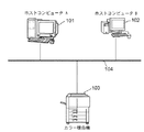
図1は第1実施形態によるデータ処理システムの構成を示す図である。図1において、101、102はホストコンピュータ、103はカラー複合機である。104はネットワークでありホストコンピュータ101、102、及びカラー複合機103を接続する。カラー複合機103は複写機能、プリント機能、ファックス機能などの複数の機能を備え、それら機能の少なくとも一部はネットワーク104を介して接続されたホストコンピュータ101、102より利用することが可能となっている。
【0010】
なお、本実施形態では、カラー複合機に本発明を適用した場合を説明するが、本発明の適用はこれに限られるものではなく、例えば(カラー或いはモノクロの)プリンタ等の単機能装置に適用することも可能である。
【0011】
第1実施形態の複合機103では、省トナー機能を使用してプリントアウトする際に、文書中の所定のオブジェクトについては消費トナー量を他のオブジェクトと比較して多く消費するようにする。特に第1実施形態では、黒い文字の部分をそのような所定のオブジェクトとする。すなわち、出力画像の黒い文字部分においては、省トナーモードにおいてもそれほど薄くならないようにプリント出力することで、文書中に多々存在する黒い文字に関しては判読性を保つことを可能にする。
【0012】
図2は第1実施形態によるプリント出力機能の構成を示す図である。ユーザは、カラー複合機103のプリント機能を利用する際に、ホストコンピュータ101或いは102(以下、ホストコンピュータ101で代表する)上のアプリケーションソフトにより文書ファイルを作成する。作成された文書ファイルは、ホストコンピュータ101上プリンタドライバ202を介して印刷ジョブ207としてカラー複合機103に送信される。
【0013】
カラー複合機103に送信された印刷ジョブ207は、カラー複合機103内のプリンタ言語解析部204で展開されてビットマップデータ208に変換される。省トナーモードの場合は更に、ビットマップデータ208の各画素が所定の属性のオブジェクトに属するか否か(本実施形態では黒い文字のオブジェクトか否か)を表す識別情報209(詳細は後述)が生成される。画像処理部205は、省トナーモードが設定されている場合には、識別情報209を参照しながらビットマップデータ208の画素値を省トナーモード用に変更する。
【0014】
ここで、画像処理部205は、省トナーモードが設定されている場合には、各画素値を省トナー記録に適した値に変換するためのLUTを参照して、ビットマップデータ208の階調値を落とす。このとき参照されるLUTが識別情報209に基づいて切り換えられる。こうしてビットマップデータ208を変換して得られたビットマップデータ210は、プリンタ部206に送信され、プリント出力物211がプリントアウトされる。
【0015】
以下、図3〜図5を参照して、本実施形態による省トナー印刷動作を詳細に説明する。
【0016】
<ホストコンピュータによる印刷ジョブの作成>
図3にホストコンピュータ101画面上に表示されるプリンタドライバメニュの一例を示す。プリンタドライバ202は図3に示すようなメニューをホストコンピュータの表示器上に表示する。省トナーモードを使用するには、図3に示したホストコンピュータ101の画面上に表示される、図3に示すようなプリンタドライバメニュー30において、省トナーモードの“ON”ボタン31を選択する。このような設定を行なうと、ホストコンピュータ101上のプリンタドライバ202は、印刷ジョブ207を生成する際に省トナーモードを選択する。なお、省トナーモードを使用しない場合には、ホストコンピュータ101の画面上に表示されるプリンタドライバメニュー30で、省トナーモードの“OFF”ボタン32を選択する。
【0017】
(印刷ジョブ生成)
プリンタドライバメニュー30におけるプリントボタン33をクリックすると、ホストコンピュータ201上のプリンタドライバ202は、各プリンタ言語に対応した印刷ジョブ207を作成する。ここで、図3に示したプリンタドライバメニュー30で省トナーモードの“ON”が設定されていると、当該印刷ジョブ207の中に省トナーモード:ONの記述が追加される。こうして作成された印刷ジョブ207は、カラー複合機103内の各プリンタ言語解析部204に送信される。
【0018】
<カラー複合機103の動作>
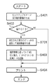
図4はカラー複合機103によるプリント動作を示すフローチャートである。この処理は印刷ジョブ207をホストコンピュータ101から受信したときに起動される。印刷ジョブ207を受信すると、プリンタ言語解析部204はビットマップデータ208を生成する(ステップS401)。また、プリンタ言語解析部204は、印刷ジョブ207に省トナーモードONの記述があるかを調べ、省トナーモードがONであれば所定の属性(黒い文字)のオブジェクトに属する画素を識別するための識別情報を生成する(S402、S403)。こうしてビットマップデータ208と識別情報209は画像処理部205へ供給される。画像処理部205は、識別情報209を参照して所定の属性のオブジェクトに属する画素とその他の画素とで異なるLUTを用いてビットマップデータを省トナーモード用のデータに変換する。
【0019】
省トナー用に変換されたビットマップデータはプリンタ部206へ提供され、プリント出力される。一方、ディプレイリスト207において省トナーモードONの記述がなければステップS402からステップS405へ進み、印刷ジョブ207に基づいて生成されたビットマップデータをそのまま用いてプリント出力が行われる。
以下各部の動作を更に詳細に説明する。
【0020】
(プリンタ言語解析部204(ステップS401〜S403))
ホストコンピュータ101上のプリンタドライバ202で生成された印刷ジョブ207を受信したカラー複合機103内のプリンタ言語解析部204は、印刷ジョブ207を解析し、ビットマップデータ208を作成する(S401)。その際に、そのビットマップデータ208に含まれるオブジェクトの識別がが行われる。オブジェクトとは、テキスト部、イメージ部、グラフィック部のことを指し、印刷ジョブ207を解析する過程で識別することができる。
【0021】
省トナーモードがプリンタドライバ202で選択されている場合(すなわち印刷ジョブ207に省トナーモードONの記述がある場合)、プリンタ言語解析部204は、テキスト部を判別しさらに、ブラックで印字されるのか、シアン、マゼンタ、イエローの3色を使用して印字されるのかも判別する。そして、テキスト部かつブラックでの印字指定のオブジェクトを、その他のオブジェクトと区別する識別情報209を作成する(S402、S403)。より具体的には、識別情報209は、例えば、各画素についてテキスト部かつブラックでの印字指定のオブジェクトに属するか他のオブジェクトに属するかを表すビットマップとなる。こうして作成されたビットマップデータ208と識別情報209は、カラー複合機203内のプリント画像処理部205に送信される。
【0022】
(画像処理部205(ステップS404))
画像処理部205は、省トナーモードの場合には、ビットマップデータ208と識別情報209を受信し、識別情報209を参照しながらLUTを切り換えてビットマップデータ208を省トナーモード用のビットマップデータ210に変換する。
【0023】
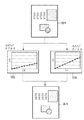
図5にカラー複合機103内の画像処理部205の動作を説明する図を示す。省トナーモードが“ON”の場合には、識別情報209には、テキスト部かつブラック指定の箇所が記述されている。画像処理部205は、ビットマップデータ31の各画素を省トナーモード用の画素値へ変換するに際して、ビットマップデータ208のテキスト部かつブラック指定の部分に関しては、トナーの載り量を可視レベルに保つルックアップテーブルA303を採用して画素値を変換する。ルックアップテーブルA303は通常の印字よりトナーの消費量を軽減するが、その軽減量は判読可能な程度に抑えられている。それに対して、その他の部分、(カラーの文字部、グラフィック部、イメージ部)に関しては、消費トナー量を最大限に抑えるルックアップテーブルB302を採用して画素値を変換する。
【0024】
以上のように、ビットマップイメージ301は、ルックアップテーブルA303とルックアップテーブルB302がオブジェクトの属性に応じて使い分けられて、ビットマップイメージ304が生成される。そして、以下、必要な画像形成処理を施し、ビットマップデータ210が生成され、カラー複合機103内のプリンタ部206に送信される。
【0025】
(プリンタ部206(S405))
ビットマップデータ210を受信したカラー複合機203内のプリンタ206は、そのビットマップデータ210に従って、プリント出力物211をプリントアウトする。
【0026】
以上のように第1実施形態における、省トナーモードによる印刷を実現するための画像処理方法によれば、ビットマップイメージが生成されるとともに該ビットマップイメージ中の所定の属性のオブジェクトの位置を表す識別情報が生成される。そして、この識別情報に基づいて、所定の属性のオブジェクトと他のオブジェクトとで異なる変換特性が適用されて、ビットマップイメージが変換され、変換されたビットマップイメージが印刷のために出力される。この構成により、属性に応じて省トナーモードにおけるトナーの軽減量をオブジェクト単位で制御でき、判読性、認識性を保つ省トナーモード印刷を実現できる。
【0027】
より具体的には、上記変換工程は、省トナーモードを実現するための第1の変換特性を有する第1変換処理(例えばLUT303を用いた処理)と、省トナーモードを実現するための前記第1の変換特性とは異なる第2の変換処理(例えばLUT302を用いた処理)を有し、所定の属性(例えばブラック指定の文字部)のオブジェクトには第1変換処理を適用し、他のオブジェクトには第2変換処理を適用する。更に具体的には、所定の属性は黒色の文字部であり、第1変換処理は第2変換処理よりも記録材の軽減の度合いが小さい変換である。
【0028】
なお、上記実施形態では、プリンタの省トナーモードへの適用を説明したので、印刷ジョブに基づいてビットマップイメージと識別情報が生成される。しかしながら、本発明の省トナーモード印刷は複写機能等にも適用できる。但し、複写機能に適用する場合には、原稿を光学的に読み取って得られたビットマップイメージに周知の領域分割処理を適用して、テキスト領域や図形領域等の抽出を行ない、所定の属性のオブジェクトの位置を示す識別情報を生成することになる。
【0029】
〔第2実施形態〕
第1実施形態では、ブラック指定の文字部を選別し、これに属する画素の画素値をルックアップテーブルA303を用いて変換し、他の画素の画素値はルックアップテーブルB302を用いて変換した。しかし、LUT切り換えのための選別は、ブラック指定の黒文字に限られるものではない。第2実施形態では、ブラック指定に限らず、全ての文字部を選別してLUTの切り換えを制御する。
【0030】
第2実施形態のシステム構成等は第1実施形態(図1〜3、5)と同様である。図6は第2実施形態によるカラー複合機によるプリント動作を示すフローチャートである。
【0031】
ホストコンピュータ101上のプリンタドライバ202で生成された印刷ジョブ207を受信したカラー複合機103内プリンタ言語解析部204において、印刷ジョブ207を解析し、ビットマップデータ208を作成する(ステップS401)。その際にそのビットマップデータ208に含まれるオブジェクトの識別を行う。オブジェクトとは、テキスト部、イメージ部、グラフィック部のことを指す。そして、省トナーモードがプリンタドライバ202で選択されている場合、プリンタ言語解析部204は、識別したオブジェクトの中からテキスト部を判別する。そして、テキスト部のオブジェクトとその他のオブジェクトを区別する識別情報209を作成する(ステップS402、S601)。作成されたビットマップデータ208と識別情報209は、カラー複合機103内の画像処理部205に送信される。
【0032】
画像処理部205では、省トナーモードの場合、上記識別情報209を参照してLUTの切り換えを制御してビットマップデータ208を省トナーモード用に変換する。すなわち、テキスト部であれば、その色に関わらず、トナーの載り量が可視的なレベルに保たれるルックアップテーブルA303が採用され、それ以外のイメージ部、グラフィック部に関しては、消費トナー量を最大限に抑えるルックアップテーブルB302が採用される(S404)。
【0033】
その後の流れは、第一の実施形態と同様である。
【0034】
以上のように、第2実施形態の省トナーモードによる印刷を実現するための画像処理方法によれば、文字部の属性を有するオブジェクトの位置を表す識別情報が生成され、省トナー印刷のための変換において、文字部における記録材の軽減の度合いが他のオブジェクトのそれよりも小さくなるように変換が行なわれる。ブラック、カラーを問わず、文字に対する判読性を向上できる。
【0035】
〔第3実施形態〕
上記第1及び第2実施形態では予め決められた固定の属性のオブジェクトを選別しているが、選別されるべき属性をユーザが指定できるようにしてもよい。第3実施形態ではそのような構成を説明する。
【0036】
第3実施形態のシステム構成等は第1実施形態(図1、2、5)と同様である。図7は第3実施形態によるカラー複合機によるプリント動作を示すフローチャートである。また、図8は、第3実施形態における、ホストコンピュータ画面上に表示されるプリンタドライバメニューの一例を示す。
【0037】
プリンタドライバ202はホストコンピュータ101上の表示器に図11に示すようなプリンタドライバメニュー80を表示する。このプリンタドライバメニュー80は例えば図3に示したプリンタドライバメニュー30において省トナーモードのONを選択した場合に表示される。このプリンタドライバメニュー80により、ユーザはボタン81から83を操作することにより省トナー機能の軽減を希望するオブジェクトを選択することができる。省トナーモードONと、省トナー機能の軽減を希望するオブジェクトの選択は印刷ジョブ207に記述されてプリンタ側に通知される。
【0038】
以上のようにして生成された印刷ジョブ207を受信したカラー複合機103内プリンタ言語解析部204は、印刷ジョブ207解析し、ビットマップデータ208を作成する(ステップS401)。その際にそのビットマップ208に含まれるオブジェクトの識別を行う。オブジェクトとは、テキスト部、イメージ部、グラフィック部のことを指す。省トナーモードがプリンタドライバ202で選択されている場合、プリンタ言語解析部204は、識別したオブジェクトの中からユーザが選択したオブジェクトを選別する。例えば、図8のメニューに示されるように、文字部とイメージ部が選択されている場合、文字部とイメージ部に属する画素を区別するビットマップが識別情報209として生成されることになる(S402、S702)。
【0039】
以上のようにして作成されたビットマップデータ208と識別情報209は、カラー複合機103内のプリント画像処理部205に送信される。この結果、ユーザが選択したオブジェクトであればトナーの載り量が可視的なレベルに保たれるルックアップテーブルA303が採用され、それ以外のイメージ部、グラフィック部に関しては、消費トナー量を最大限に抑えるルックアップテーブルB302が採用されて省トナーモード用のビットマップデータ210が生成される。その後の流れは、第1実施形態と同様である。
【0040】
以上のように、上記各実施形態によれば、省トナーモードにおいて、所定の属性のオブジェクトについてトナーの軽減量を抑えるので、必要なオブジェクトを比較的明瞭に保つことができる。例えば第1実施形態によれば、一般文書内で多く使用されている黒い文字に関しては人間が読むことができる程度の消費トナー量の軽減で収めて、その他のオブジェクトに関しては、できる限り消費トナー量を節減することで、出力物に何が書かれているかは、読むことができ、消費トナー量も軽減できる。すなわち、トナー消費量を節約する目的で省トナーモードでのプリントを実行した場合に、文書内すべてのオブジェクトに対して消費トナー量を節約すると判読性が損なわれるという課題が解決される。
【0041】
また、第2実施形態のように、黒い文字に限定せず、文字部をすべて読めるようなトナー消費量を適応することも可能である。また、第3実施形態によれば、所望の属性を指定する環境をユーザに提供し、指定された属性のオブジェクトとその他のオブジェクトで省トナーの度合いを変更する。ユーザの要求に応じて認識性を維持するオブジェクトを設定できるので、便利である。
【0042】
なお、上記実施形態ではホストコンピュータ側で省トナーモードや、トナーの軽減量を押さえるべき属性の指定を行なったが、プリンタ側で行なうようにしてもよい。この場合、印刷ジョブ207に省トナーモードON、OFFを記述したり、指定された属性を記述する必要はなくなる。
【0043】
なお、以上のようなビットマップデータの生成処理をホストコンピュータ内のプリンタドライバによって行なうことも可能である。従って本発明の目的は、前述した実施形態の機能を実現するソフトウェアのプログラムコードを記録した記憶媒体を、システムあるいは装置に供給し、そのシステムあるいは装置のコンピュータ(またはCPUやMPU)が記憶媒体に格納されたプログラムコードを読出し実行することによっても、達成されるものである。
【0044】
この場合、記憶媒体から読出されたプログラムコード自体が前述した実施形態の機能を実現することになり、そのプログラムコードを記憶した記憶媒体は本発明を構成することになる。
【0045】
プログラムコードを供給するための記憶媒体としては、例えば、フレキシブルディスク,ハードディスク,光ディスク,光磁気ディスク,CD−ROM,CD−R,磁気テープ,不揮発性のメモリカード,ROMなどを用いることができる。
【0046】
また、コンピュータが読出したプログラムコードを実行することにより、前述した実施形態の機能が実現されるだけでなく、そのプログラムコードの指示に基づき、コンピュータ上で稼働しているOS(オペレーティングシステム)などが実際の処理の一部または全部を行い、その処理によって前述した実施形態の機能が実現される場合も含まれることは言うまでもない。
【0047】
さらに、記憶媒体から読出されたプログラムコードが、コンピュータに挿入された機能拡張ボードやコンピュータに接続された機能拡張ユニットに備わるメモリに書込まれた後、そのプログラムコードの指示に基づき、その機能拡張ボードや機能拡張ユニットに備わるCPUなどが実際の処理の一部または全部を行い、その処理によって前述した実施形態の機能が実現される場合も含まれることは言うまでもない。
【0048】
【発明の効果】
以上説明したように、本発明によれば、必要な認識性及び/又は可読性を維持しながらトナー消費量を低減した画像記録が可能となる。
【図面の簡単な説明】
【図1】第1実施形態によるデータ処理システムの構成を示す図である。
【図2】第1実施形態によるプリント出力機能の構成を示す図である。
【図3】ホストコンピュータ101画面上に表示されるプリンタドライバメニュの一例を示す図である。
【図4】第1実施形態におけるカラー複合機103によるプリント動作を示すフローチャートである。
【図5】カラー複合機103内の画像処理部205の動作を説明する図である。
【図6】第2実施形態におけるカラー複合機103によるプリント動作を示すフローチャートである。
【図7】第3実施形態におけるカラー複合機103によるプリント動作を示すフローチャートである。
【図8】第3実施形態における、ホストコンピュータ画面上に表示されるプリンタドライバメニューの一例を示す図である。[0001]
TECHNICAL FIELD OF THE INVENTION
1. Field of the Invention The present invention relates to an image processing technique when printing and outputting while saving toner consumption.
[0002]
[Prior art]
2. Description of the Related Art In recent years, in offices and copy shops, color and monochrome multifunction peripherals have been increasingly installed. A multifunction device has a plurality of functions such as a copying function, a printing function, and a facsimile function. By purchasing one such multifunction device, all of the above functions can be used, and by connecting to a network, a plurality of users can use these functions via a plurality of host computers. Become.
[0003]
However, the running cost of the color MFP is high. One of the causes is consumption of toner. For this reason, in the case where the department management of the color multifunction peripheral is strict, there is a situation in which the user cannot output the test output to check the configuration of the output product.
[0004]
Therefore, such a multifunction peripheral is often equipped with a function for reducing the amount of toner consumed in the printing function of the multifunction peripheral in order to reduce the running cost. Particularly in the case of a color multifunction peripheral having a high running cost, such a toner saving function is an effective function. Further, the usefulness of such a toner saving function is not limited to a multifunction device, but also applies to a printer which is a single function device.
[0005]
[Problems to be solved by the invention]
However, when printing is performed using the toner saving function, the amount of consumed toner is reduced, but decoding may not be possible due to the small amount of applied toner. There is no point in printing out if you can't decipher it. In addition, in order to obtain a readable output, it is necessary to increase the amount of applied toner in the entire image, that is, to increase the amount of consumed toner. Is a story that is not thankful.
[0006]
The present invention has been made in view of the above problems, and has as its object to enable image recording with reduced toner consumption while maintaining necessary recognition and / or readability.
[0007]
[Means for Solving the Problems]
An image processing method according to the present invention for achieving the above object,
An image processing method for printing in a toner-saving mode,
A bitmap image, and a generating step of generating identification information indicating a position of an object having a predetermined attribute in the bitmap image;
Based on the identification information, applying a different conversion characteristics between the object of the predetermined attribute and other objects, a conversion step of converting the bitmap image,
An output step of outputting the bitmap image converted in the conversion step.
[0008]
BEST MODE FOR CARRYING OUT THE INVENTION
Hereinafter, preferred embodiments of the present invention will be described with reference to the accompanying drawings.
[0009]
[First Embodiment]
FIG. 1 is a diagram showing the configuration of the data processing system according to the first embodiment. In FIG. 1,
[0010]
In the present embodiment, the case where the present invention is applied to a color multifunction peripheral will be described. However, the present invention is not limited to this, and is applied to a single-function device such as a (color or monochrome) printer. It is also possible.
[0011]
In the multifunction peripheral 103 according to the first embodiment, when printing out using the toner saving function, a predetermined object in a document consumes a larger amount of toner than other objects. In particular, in the first embodiment, a black character portion is set as such a predetermined object. That is, in the black character portion of the output image, the printout is performed so that the black character portion is not so thin even in the toner saving mode, so that it is possible to maintain the legibility of the black character which is often present in the document.
[0012]
FIG. 2 is a diagram illustrating the configuration of the print output function according to the first embodiment. When using the print function of the
[0013]
The print job 207 transmitted to the
[0014]
Here, when the toner saving mode is set, the
[0015]
Hereinafter, the toner-saving printing operation according to the present embodiment will be described in detail with reference to FIGS.
[0016]
<Create print job by host computer>
FIG. 3 shows an example of a printer driver menu displayed on the
[0017]
(Print job generation)
When a
[0018]
<Operation of
FIG. 4 is a flowchart illustrating a printing operation performed by the
[0019]
The bitmap data converted for toner saving is provided to the
Hereinafter, the operation of each unit will be described in more detail.
[0020]
(Printer language analysis unit 204 (steps S401 to S403))
Upon receiving the print job 207 generated by the
[0021]
When the toner saving mode is selected by the printer driver 202 (that is, when the print job 207 includes a description of the toner saving mode ON), the printer
[0022]
(Image processing unit 205 (step S404))
In the case of the toner saving mode, the
[0023]
FIG. 5 is a diagram illustrating the operation of the
[0024]
As described above, in the
[0025]
(Printer 206 (S405))
The
[0026]
As described above, according to the image processing method for realizing printing in the toner-saving mode in the first embodiment, a bitmap image is generated and the position of an object having a predetermined attribute in the bitmap image is indicated. Identification information is generated. Then, based on the identification information, different conversion characteristics are applied between the object having the predetermined attribute and another object, the bitmap image is converted, and the converted bitmap image is output for printing. With this configuration, the amount of toner reduction in the toner saving mode can be controlled for each object according to the attribute, and toner saving mode printing that maintains legibility and recognition can be realized.
[0027]
More specifically, the conversion step includes a first conversion process (for example, a process using the LUT 303) having a first conversion characteristic for realizing the toner saving mode, and the first conversion process for realizing the toner saving mode. 1 has a second conversion process (for example, a process using the LUT 302) that is different from the first conversion characteristic. The first conversion process is applied to an object having a predetermined attribute (for example, a character portion designated as black), Apply the second conversion process. More specifically, the predetermined attribute is a black character portion, and the first conversion process is a conversion in which the degree of reduction of the recording material is smaller than that of the second conversion process.
[0028]
In the above embodiment, the application of the printer to the toner saving mode has been described, so that the bitmap image and the identification information are generated based on the print job. However, the toner saving mode printing of the present invention can also be applied to a copying function or the like. However, when applied to the copy function, a known area division process is applied to a bitmap image obtained by optically reading an original to extract a text area, a graphic area, and the like, and to obtain a predetermined attribute. The identification information indicating the position of the object will be generated.
[0029]
[Second embodiment]
In the first embodiment, a character portion designated as black is selected, the pixel value of a pixel belonging to the selected character portion is converted using a lookup table A303, and the pixel value of another pixel is converted using a lookup table B302. However, the selection for switching the LUT is not limited to black characters designated as black. In the second embodiment, the switching of the LUT is controlled by selecting not only the black designation but also all character portions.
[0030]
The system configuration and the like of the second embodiment are the same as those of the first embodiment (FIGS. 1 to 3 and 5). FIG. 6 is a flowchart showing a printing operation by the color MFP according to the second embodiment.
[0031]
Upon receiving the print job 207 generated by the
[0032]
In the case of the toner saving mode, the
[0033]
The subsequent flow is the same as in the first embodiment.
[0034]
As described above, according to the image processing method for realizing printing in the toner-saving mode of the second embodiment, the identification information indicating the position of the object having the character portion attribute is generated, and In the conversion, the conversion is performed such that the degree of reduction of the recording material in the character portion is smaller than that of the other objects. Regardless of black or color, legibility of characters can be improved.
[0035]
[Third embodiment]
In the first and second embodiments, objects having predetermined fixed attributes are selected. However, the user may be allowed to specify an attribute to be selected. In the third embodiment, such a configuration will be described.
[0036]
The system configuration and the like of the third embodiment are the same as those of the first embodiment (FIGS. 1, 2, and 5). FIG. 7 is a flowchart illustrating a printing operation by the color multifunction peripheral according to the third embodiment. FIG. 8 shows an example of a printer driver menu displayed on the host computer screen in the third embodiment.
[0037]
The
[0038]
Upon receiving the print job 207 generated as described above, the printer
[0039]
The bitmap data 208 and
[0040]
As described above, according to each of the above-described embodiments, in the toner saving mode, the amount of toner reduction for an object having a predetermined attribute is suppressed, so that necessary objects can be kept relatively clear. For example, according to the first embodiment, black characters that are frequently used in a general document can be reduced by reducing the amount of toner consumption that can be read by a human, and the remaining objects can be reduced as much as possible. , The user can read what is written on the output, and reduce the amount of toner consumed. That is, when printing is performed in the toner-saving mode for the purpose of saving toner consumption, it is possible to solve the problem that legibility is impaired if the consumption toner amount is reduced for all objects in the document.
[0041]
Further, as in the second embodiment, the toner consumption is not limited to black characters, but can be adapted so that the entire character portion can be read. Further, according to the third embodiment, an environment for designating a desired attribute is provided to the user, and the degree of toner saving is changed between the object having the designated attribute and other objects. This is convenient because an object that maintains recognizability can be set according to a user's request.
[0042]
In the above-described embodiment, the host computer specifies the toner saving mode and the attribute for suppressing the toner reduction amount. However, the printer may perform the specification. In this case, there is no need to describe the toner save mode ON or OFF or the designated attribute in the print job 207.
[0043]
Note that the above bitmap data generation processing can be performed by a printer driver in the host computer. Accordingly, an object of the present invention is to provide a storage medium storing a program code of software for realizing the functions of the above-described embodiments to a system or an apparatus, and a computer (or CPU or MPU) of the system or apparatus to store the storage medium in the storage medium. This is also achieved by reading and executing the stored program code.
[0044]
In this case, the program code itself read from the storage medium realizes the function of the above-described embodiment, and the storage medium storing the program code constitutes the present invention.
[0045]
As a storage medium for supplying the program code, for example, a flexible disk, a hard disk, an optical disk, a magneto-optical disk, a CD-ROM, a CD-R, a magnetic tape, a nonvolatile memory card, a ROM, and the like can be used.
[0046]
When the computer executes the readout program code, not only the functions of the above-described embodiments are realized, but also an OS (Operating System) running on the computer based on the instruction of the program code. It goes without saying that a part or all of the actual processing is performed and the functions of the above-described embodiments are realized by the processing.
[0047]
Further, after the program code read from the storage medium is written into a memory provided on a function expansion board inserted into the computer or a function expansion unit connected to the computer, the function expansion is performed based on the instruction of the program code. It goes without saying that a CPU or the like provided in the board or the function expansion unit performs part or all of the actual processing, and the processing realizes the functions of the above-described embodiments.
[0048]
【The invention's effect】
As described above, according to the present invention, it is possible to perform image recording with reduced toner consumption while maintaining necessary recognizability and / or readability.
[Brief description of the drawings]
FIG. 1 is a diagram showing a configuration of a data processing system according to a first embodiment.
FIG. 2 is a diagram illustrating a configuration of a print output function according to the first embodiment.
FIG. 3 is a diagram illustrating an example of a printer driver menu displayed on a screen of a
FIG. 4 is a flowchart illustrating a printing operation performed by the color MFP according to the first exemplary embodiment.
FIG. 5 is a diagram illustrating an operation of an
FIG. 6 is a flowchart illustrating a printing operation performed by the color multifunction peripheral 103 according to the second embodiment.
FIG. 7 is a flowchart illustrating a printing operation performed by the color MFP according to a third embodiment.
FIG. 8 is a diagram illustrating an example of a printer driver menu displayed on a host computer screen according to a third embodiment.
Claims (1)
ビットマップイメージと、該ビットマップイメージ中の所定の属性のオブジェクトの位置を表す識別情報を生成する生成工程と、
前記識別情報に基づいて、前記所定の属性のオブジェクトと他のオブジェクトとで異なる変換特性を適用して、前記ビットマップイメージを変換する変換工程と、
前記変換工程で変換されたビットマップイメージを出力する出力工程とを備えることを特徴とする画像処理方法。An image processing method for printing in a toner-saving mode,
A bitmap image, and a generating step of generating identification information indicating a position of an object having a predetermined attribute in the bitmap image;
A conversion step of converting the bitmap image by applying different conversion characteristics between the object having the predetermined attribute and another object based on the identification information,
An output step of outputting the bitmap image converted in the conversion step.
Priority Applications (1)
| Application Number | Priority Date | Filing Date | Title |
|---|---|---|---|
| JP2002334216A JP2004167755A (en) | 2002-11-18 | 2002-11-18 | Image processing method |
Applications Claiming Priority (1)
| Application Number | Priority Date | Filing Date | Title |
|---|---|---|---|
| JP2002334216A JP2004167755A (en) | 2002-11-18 | 2002-11-18 | Image processing method |
Publications (2)
| Publication Number | Publication Date |
|---|---|
| JP2004167755A true JP2004167755A (en) | 2004-06-17 |
| JP2004167755A5 JP2004167755A5 (en) | 2005-07-28 |
Family
ID=32698730
Family Applications (1)
| Application Number | Title | Priority Date | Filing Date |
|---|---|---|---|
| JP2002334216A Pending JP2004167755A (en) | 2002-11-18 | 2002-11-18 | Image processing method |
Country Status (1)
| Country | Link |
|---|---|
| JP (1) | JP2004167755A (en) |
Cited By (2)
| Publication number | Priority date | Publication date | Assignee | Title |
|---|---|---|---|---|
| JP2007272808A (en) * | 2006-03-31 | 2007-10-18 | Oki Data Corp | Image forming apparatus, information processor and image forming system |
| US8472079B2 (en) | 2009-05-18 | 2013-06-25 | Canon Kabushiki Kaisha | Image processing apparatus, method, and program product for display and control of color material amount used in seperated object areas |
Citations (6)
| Publication number | Priority date | Publication date | Assignee | Title |
|---|---|---|---|---|
| JPH07107280A (en) * | 1993-10-06 | 1995-04-21 | Matsushita Electric Ind Co Ltd | Picture forming device |
| JP2001083845A (en) * | 1999-09-14 | 2001-03-30 | Canon Inc | Method and device for image processing |
| JP2001219626A (en) * | 2000-02-08 | 2001-08-14 | Ricoh Co Ltd | Printing system |
| JP2001334700A (en) * | 2000-05-24 | 2001-12-04 | Sharp Corp | Image processor |
| JP2002214862A (en) * | 2001-01-22 | 2002-07-31 | Canon Inc | Image forming device, image forming method and storage medium with image forming procedure stored |
| JP2004101870A (en) * | 2002-09-10 | 2004-04-02 | Seiko Epson Corp | Image forming apparatus and coloring agent saving method |
-
2002
- 2002-11-18 JP JP2002334216A patent/JP2004167755A/en active Pending
Patent Citations (6)
| Publication number | Priority date | Publication date | Assignee | Title |
|---|---|---|---|---|
| JPH07107280A (en) * | 1993-10-06 | 1995-04-21 | Matsushita Electric Ind Co Ltd | Picture forming device |
| JP2001083845A (en) * | 1999-09-14 | 2001-03-30 | Canon Inc | Method and device for image processing |
| JP2001219626A (en) * | 2000-02-08 | 2001-08-14 | Ricoh Co Ltd | Printing system |
| JP2001334700A (en) * | 2000-05-24 | 2001-12-04 | Sharp Corp | Image processor |
| JP2002214862A (en) * | 2001-01-22 | 2002-07-31 | Canon Inc | Image forming device, image forming method and storage medium with image forming procedure stored |
| JP2004101870A (en) * | 2002-09-10 | 2004-04-02 | Seiko Epson Corp | Image forming apparatus and coloring agent saving method |
Cited By (3)
| Publication number | Priority date | Publication date | Assignee | Title |
|---|---|---|---|---|
| JP2007272808A (en) * | 2006-03-31 | 2007-10-18 | Oki Data Corp | Image forming apparatus, information processor and image forming system |
| US8395810B2 (en) | 2006-03-31 | 2013-03-12 | Oki Data Corporation | Image forming apparatus, information processing apparatus, and image forming system |
| US8472079B2 (en) | 2009-05-18 | 2013-06-25 | Canon Kabushiki Kaisha | Image processing apparatus, method, and program product for display and control of color material amount used in seperated object areas |
Similar Documents
| Publication | Publication Date | Title |
|---|---|---|
| US7751073B2 (en) | Image processing device, method, and program product with control of display screens based on selected application | |
| US20070086050A1 (en) | Information processing apparatus, image processing method, and machine-readable medium | |
| US7612910B2 (en) | Information processing apparatus, information processing system, information output control method, storage medium and program | |
| US20060098220A1 (en) | Method and apparatus to generate a preview image | |
| JPH07254060A (en) | Image processing method and device | |
| US20060109528A1 (en) | Image processing apparatus managing user profiles, image processing method managing user profiles, and storage medium thereof | |
| US6247028B1 (en) | Controlling attributes of pre-registered form data to match those of data to be printed with the form data | |
| JP2008077160A (en) | Image processing device, image processing method, image forming apparatus, computer-executable program, and recording medium storing the program | |
| JP2006155308A (en) | Image forming apparatus | |
| US6851875B2 (en) | Printer and print image reference system | |
| JP2004167755A (en) | Image processing method | |
| JP2004157904A (en) | Printer control program and printer | |
| US20040246511A1 (en) | Method and system for graphically communicating print mode quality speed | |
| KR100691468B1 (en) | Printing method for security document and image reproduction apparatus | |
| JP4522006B2 (en) | Information processing apparatus, information processing method, and printer driver program | |
| KR100571788B1 (en) | The method of printing the appointed domain of document enlargeably | |
| JP2005242828A (en) | Information processing system, control method of same, image forming device, and control program | |
| JP2007148638A (en) | Print data generation program, print data generation method and print data generation device | |
| JP4298579B2 (en) | Image processing method and print control apparatus | |
| JPH11345100A (en) | Printer | |
| JP3728083B2 (en) | Image output apparatus and image output method | |
| JP2003099216A (en) | Print setting method for printer driver, information processor, program, and storage medium | |
| JPH10285412A (en) | Image coding unit and method therefor | |
| JP2001078036A (en) | Device and method for processing image | |
| JP2004192570A (en) | Method for supplying print data to printer without using graphics device interface of operating system |
Legal Events
| Date | Code | Title | Description |
|---|---|---|---|
| A621 | Written request for application examination |
Free format text: JAPANESE INTERMEDIATE CODE: A621 Effective date: 20041213 |
|
| A521 | Written amendment |
Free format text: JAPANESE INTERMEDIATE CODE: A523 Effective date: 20041221 |
|
| A977 | Report on retrieval |
Free format text: JAPANESE INTERMEDIATE CODE: A971007 Effective date: 20061129 |
|
| A131 | Notification of reasons for refusal |
Free format text: JAPANESE INTERMEDIATE CODE: A131 Effective date: 20061204 |
|
| A521 | Written amendment |
Free format text: JAPANESE INTERMEDIATE CODE: A523 Effective date: 20070202 |
|
| A02 | Decision of refusal |
Free format text: JAPANESE INTERMEDIATE CODE: A02 Effective date: 20080725 |