JP2004166364A - Charger and charging method - Google Patents
Charger and charging method Download PDFInfo
- Publication number
- JP2004166364A JP2004166364A JP2002328219A JP2002328219A JP2004166364A JP 2004166364 A JP2004166364 A JP 2004166364A JP 2002328219 A JP2002328219 A JP 2002328219A JP 2002328219 A JP2002328219 A JP 2002328219A JP 2004166364 A JP2004166364 A JP 2004166364A
- Authority
- JP
- Japan
- Prior art keywords
- charger
- battery
- side terminal
- state
- secondary battery
- Prior art date
- Legal status (The legal status is an assumption and is not a legal conclusion. Google has not performed a legal analysis and makes no representation as to the accuracy of the status listed.)
- Pending
Links
Images


Classifications
-
- Y—GENERAL TAGGING OF NEW TECHNOLOGICAL DEVELOPMENTS; GENERAL TAGGING OF CROSS-SECTIONAL TECHNOLOGIES SPANNING OVER SEVERAL SECTIONS OF THE IPC; TECHNICAL SUBJECTS COVERED BY FORMER USPC CROSS-REFERENCE ART COLLECTIONS [XRACs] AND DIGESTS
- Y02—TECHNOLOGIES OR APPLICATIONS FOR MITIGATION OR ADAPTATION AGAINST CLIMATE CHANGE
- Y02E—REDUCTION OF GREENHOUSE GAS [GHG] EMISSIONS, RELATED TO ENERGY GENERATION, TRANSMISSION OR DISTRIBUTION
- Y02E60/00—Enabling technologies; Technologies with a potential or indirect contribution to GHG emissions mitigation
- Y02E60/10—Energy storage using batteries
Landscapes
- Charge And Discharge Circuits For Batteries Or The Like (AREA)
- Secondary Cells (AREA)
Abstract
【課題】二次電池を充電するにあたり、二次電池の接続を検出する機能を有すると共に二次電池の小型化・薄型化を可能にしつつ、さらに、二次電池が過充電状態に至るのを防止できる充電器および充電方法を提供する。
【解決手段】充電器11は、外部から充電器正極端子41と充電器負極端子43との間に印加される端子部両端電圧V_Batが、リチウムイオン電池13の使用可能領域に含まれる場合には、充電器側端子部41,43と電池側端子部61,63とが接続状態であると判定し、リチウムイオン電池13に対して充電用の電力供給を行う。つまり、充電器11は、リチウムイオン電池13との接続判定を行うにあたり、内部のACアダプタ23から一対の充電器側端子部41,43に電力供給を行わないため、リチウムイオン電池13への電圧印加が行われなくなり、リチウムイオン電池13が過充電状態になるのを防止できる。
【選択図】 図1To charge a secondary battery, the secondary battery has a function of detecting a connection of the secondary battery, and enables a reduction in size and thickness of the secondary battery. Provided is a charger and a charging method that can be prevented.
A battery charger includes a battery charger that includes a terminal-side voltage V_Bat externally applied between a battery charger positive terminal and a battery charger negative terminal in a usable area of a lithium ion battery. Then, it is determined that the charger-side terminal portions 41 and 43 and the battery-side terminal portions 61 and 63 are in a connected state, and power is supplied to the lithium-ion battery 13 for charging. That is, the charger 11 does not supply power to the pair of charger-side terminals 41 and 43 from the internal AC adapter 23 when making a connection determination with the lithium-ion battery 13. It is possible to prevent the voltage from being applied and prevent the lithium ion battery 13 from being overcharged.
[Selection diagram] Fig. 1
Description
【0001】
【発明の属する技術分野】
本発明は、一対の充電器側端子部から二次電池の電池側端子部に対して電力供給を行うことで二次電池を充電する充電器、およびそのような充電器を用いて二次電池を充電する充電方法に関する。
【0002】
【従来の技術】
従来より、充放電可能に構成された二次電池と、二次電池に対して電力供給することで二次電池を充電する充電器と、が知られている。
なお、二次電池の充電に際しては、二次電池に対する電力供給が過剰となり過充電状態に至ると、二次電池が破裂・発火するなどの危険性がある。
【0003】
また、蓄積電力が過剰に放電されて過放電状態となった二次電池については、電池内部の構成材料(負極の集電体(Cu))の一部が溶け出すことがあり、溶け出した構成材料は、二次電池を充電する際に、針状形状となって析出する場合がある。このとき、針状形状となった構成材料が通電経路を短絡(ショート)することがあり、針状の構成材料による通電経路の短絡に伴って、二次電池が破裂・発火する危険性がある。
【0004】
そこで、こうした問題に対しては、二次電池が過充電状態・過放電状態になるのを防止するための充放電装置が提案されている(特許文献1参照)。この装置は、充電作業時に二次電池が満充電状態になると、バイパス回路により二次電池への充電電力をバイパスするため、二次電池が過充電状態になるのを防止でき、また、放電時に二次電池が過放電状態に近づくと、過放電警報を送出するため、二次電池が過放電状態になるのを防止できる。
【0005】
つまり、二次電池の充電状態(換言すれば、充電残容量)を正常充電状態(過放電状態・過充電状態ではない状態)である使用可能領域となるよう制御して、二次電池の充電状態が過充電状態や過放電状態などの使用厳禁領域に至るのを防止するのである。使用可能領域に制御された二次電池は、破裂・発火などの危険を伴うことなく安全に充電作業を行うことができ、また、充電作業後には電気機器に対して正常に電力供給を行うことができる。
【0006】
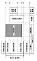
ここで、出力電圧を基準として、二次電池の使用可能領域および使用厳禁領域を表した説明図を図4に示す。なお、図4では、縦軸が二次電池の出力電圧であり、図において上になるほど電圧値が大きくなるよう領域を表しており、二次電池として後述する保護回路を備えた電池パックを例に挙げて、各領域を表している。また、第1電圧V1は0[V]よりも大きく、第1電圧V1から順番に、第2電圧V2、第3電圧V3、第4電圧V4、第5電圧V5になるほど、電圧値が大きくなる。
【0007】
図4では、0[V]から第1電圧V1までの使用厳禁領域が過放電状態を表し、また、第5電圧V5よりも大きい領域の使用厳禁領域が過充電状態を表す。このことから、充電器の充電器動作領域、保護回路の作動領域および電気機器の機器使用領域は、使用厳禁領域を含まないように設定することで、二次電池が過充電状態になるのを防止でき、また、過放電状態の二次電池への充電作業を避けることができる。
【0008】
また、二次電池は、使用可能領域であっても、充電残容量が多い場合や少ない場合には、耐久性(寿命)への悪影響があるため、第3電圧V3から第4電圧V4までの領域が耐久性への悪影響が少ない通常使用領域であるのに対して、第1電圧V1から第3電圧V3までの領域、および第4電圧V4から第5電圧V5までの領域は、耐久性への悪影響が大きい寿命低下領域となる。このため、充電器動作領域や機器使用領域は、寿命低下領域を考慮して設定することで、二次電池の耐久性を向上させることが出来る。
【0009】
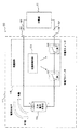
ところで、充電器は、上記特許文献に記載された装置のように二次電池と一体に構成されるものに限られず、二次電池とは別体に構成することができる。図5に、二次電池とは別体に構成される充電器103と、二次電池105とを有して構成される充電システム101(以下、従来型充電システム101ともいう)の概略構成図を示す。
【0010】
この従来型充電システム101に備えられる充電器103は、二次電池105に備えられる一対の電池側端子部109と電気的に接続可能に配置される一対の充電器側端子部107を備えている。そして充電器側端子部107と電池側端子部109とを接続して、充電器側端子部107から電池側端子部109に対して(換言すれば、充電器103から二次電池105に対して)電力供給を行うことで、二次電池105を充電する。
【0011】
また、充電器103は、二次電池105が接続されたことを検出するために、内部の電力供給源(図示省略)から一対の充電器側端子部107に対して接続確認用電圧を印加するよう構成されている。つまり、二次電池105が未接続の状態では、接続確認用電圧を印加しても、一対の充電器側端子部107の間には通電経路が存在しないため電流は流れないのに対し、二次電池105が接続された状態であれば、二次電池105が通電経路として機能するため、接続確認用電圧の印加時に一対の充電器側端子部107の間に電流が流れる。
【0012】
このように構成された充電器103によれば、二次電池105が接続されたことを充電器103が判断できるため、二次電池105を充電器103に接続した後、使用者が充電開始スイッチを操作するなどの充電開始操作を行うことなく充電作業を開始できるため、充電作業の煩雑さを解消することが出来る。
【0013】
なお、この充電器103は、満充電状態の二次電池が接続された場合においても、確実に二次電池105に対して電流を流すことが出来るように、接続確認用電圧として、二次電池105の使用可能領域の上限電圧(図4における第5電圧V5)よりも大きい電圧値を、一対の充電器側端子部107に印加するよう構成されている。この場合、接続確認用電圧の印加時間を短時間に設定することで、接続確認用電圧の印加による二次電池の破損が発生するのを防止できる。
【0014】
【特許文献1】
特開2002−223525号公報(請求項1、図1、段落番号[0009]、段落番号[0016]〜[0017])
【0015】
【発明が解決しようとする課題】
しかし、内部の電力供給源から一対の充電器側端子部に対して接続確認用電圧を印加する構成の充電器103(以下、従来型充電器103ともいう)においては、二次電池の接続確認動作(接続確認用電圧の印加動作)が繰り返し行われることに起因して、二次電池105が過充電状態に至る虞がある。
【0016】
つまり、二次電池105は、従来型充電器103に接続される毎に、自身の定格出力電圧値よりも大きい接続確認用電圧が印加されることから、接続確認用電圧によって少しずつ充電残容量が増加することになる。なお、接続確認用電圧の印加時間を短く設定して、接続確認用電圧の印加に伴う充電量の増加を抑えることで、一回の接続確認用電圧の印加作業により二次電池が過充電状態に至ることは抑制できる。
【0017】
しかしながら、二次電池の用途によっては、充電器からの離脱後、ほとんど電力消費が行われない状態で再び充電器に接続される場合があり、このように電力消費量が少ない状態での充電器への接続・離脱が頻繁に繰り返されると、二次電池が過充電状態に至る可能性がある。
【0018】
これに対して、上記の特許文献に記載の装置は、充電作業時において二次電池が過充電状態に至るのを防止することはできるものの、充電作業よりも前に実行される二次電池の接続確認動作に起因する過充電を防止することは出来ない。
また、内部の電力供給源から一対の充電器側端子部に対して接続確認用電圧を印加する構成の従来型充電器103は、過放電状態の二次電池が接続された場合に、上述したように、電池内部の構成材料が針状に析出することに起因して、二次電池が破裂・発火する虞がある。
【0019】
このような問題に対しては、電力を蓄積する二次電池本体部と、過放電または過充電を防止するための保護回路とが一体に備えられた保護回路一体型二次電池(いわゆる電池パック)を、上記の二次電池105に代えて用いることが考えられる。
【0020】
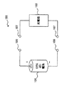
図6に、電池パック111と充電器133とを有して構成される第2従来型充電システム110の概略構成図を示す。なお、充電器133は、従来型充電器103と同様の構成であり、一対の充電器側端子部137が一対の充電器側端子部107に相当する。
【0021】
電池パック111は、二次電池本体部113と、保護回路115と、充電器133の一対の充電器側端子部137に接続可能な一対の電池パック側端子部119と、を備えて構成されている。
保護回路115においては、保護制御回路121がFETからなる放電用スイッチ123および充電用スイッチ125を駆動制御して、放電時の電流方向と充電時の電流方向を反転させて、充電動作および放電動作のそれぞれの電流方向を制御する。また、保護回路115は、二次電池本体部113に過大電流が流れた場合には、保護制御回路121が放電用スイッチ123および充電用スイッチ125を開放状態に駆動制御して、二次電池本体部113が過充電状態に至るのを防止する。さらに、保護回路115は、二次電池本体部113が過放電状態に至る前に、保護制御回路121が放電用スイッチ123および充電用スイッチ125を開放状態に駆動制御することで、二次電池本体部113が過放電状態に至るのを防止することができる。
【0022】
このように保護回路を有する電池パックは、二次電池本体部が過充電状態・過放電状態になるのを防止できるため、安全性が向上するという利点がある。
しかし、近年、二次電池の用途の多様化から、二次電池に対して小型化・薄型化の要求が高まっているのに対して、保護回路を備える二次電池(詳細には、電池パック)は、保護回路を備える分だけ体積が大きくなるため、小型化・薄型化の要求に応えられないという問題がある。このため、小型化・薄型化が優先される用途においては、保護回路を有さない構成の二次電池を用いる必要があるが、過充電状態や過放電状態になる可能性が高くなり、二次電池の寿命が短くなるという問題が生じる。
【0023】
そこで、本発明は、こうした問題に鑑みなされたものであり、二次電池を充電するにあたり、二次電池の接続を検出する機能を有すると共に二次電池の小型化・薄型化を可能にしつつ、さらに、二次電池が過充電状態に至るのを防止できる充電器および充電方法を提供することを目的とする。
【0024】
【課題を解決するための手段】
かかる目的を達成するためになされた本発明の第1態様は、二次電池を充電するための充電電力を供給する電力供給手段と、電力伝達経路を介して電力供給手段に電気的に接続されると共に、二次電池に備えられる一対の電池側端子部と電気的に接続可能に配置される一対の充電器側端子部と、充電器側端子部と電池側端子部とが接続状態である場合には、電力伝達経路を通電状態に制御し、充電器側端子部と電池側端子部とが未接続状態である場合には、電力伝達経路を遮断状態に制御する充電状態制御手段と、を備えて、二次電池を充電する充電器であって、外部から一対の充電器側端子部に対して供給される電力の供給状態である外部電力供給状態が、正常動作時の二次電池による電力の供給状態である正常電池電力供給状態と同等になる場合には、充電器側端子部と電池側端子部とが接続状態であると判定し、外部電力供給状態が正常電池電力供給状態と異なる場合には、充電器側端子部と電池側端子部とが未接続状態であると判定する接続状態判定手段を備え、充電状態制御手段が、接続状態判定手段での判定結果に基づき、電力伝達経路の状態を制御することを特徴とする。
【0025】
また、上記目的を達成するためになされた本発明の1方法は、二次電池に備えられる一対の電池側端子部と電気的に接続可能に配置される一対の充電器側端子部を備える充電器を用いて、二次電池を充電する充電方法であって、外部から一対の充電器側端子部に対して供給される電力の供給状態である外部電力供給状態が、正常動作時の二次電池による電力の供給状態である正常電池電力供給状態と同等になる場合には、充電器側端子部と電池側端子部とが接続状態であると判定して、充電器側端子部から電池側端子部に対する電力供給を行い、外部電力供給状態が正常電池電力供給状態と異なる場合には、充電器側端子部と電池側端子部とが未接続状態であると判定して、充電器側端子部から電池側端子部に対する電力供給を行わないことを特徴とする。
【0026】
つまり、本発明の充電器および充電方法においては、二次電池が接続されたか否かを判断するにあたり、内部の電力供給手段から一対の充電器側端子部に電力供給を行うのではなく、外部から一対の充電器側端子部に供給される外部電力供給状態に基づいて、二次電池の電池側端子部が充電器側端子部に接続されたか否かを判定する。
【0027】
これにより、二次電池に対する接続確認用電圧の印加に起因して、二次電池の充電量が増加するのを避けることが出来る。
そして、二次電池の電池側端子部が充電器側端子部に接続されると、二次電池の出力電力が充電器に対して供給されることから、外部電力供給状態が、正常動作時の二次電池による正常電池電力供給状態と同等になる場合には、充電器側端子部と電池側端子部とが接続状態であると判定することができる。ここで、正常動作時の二次電池とは、例えば、上述の使用可能領域に含まれる状態の二次電池を指す。
【0028】
なお、本発明では、接続判定に際して二次電池が電力供給するため、放電状態の二次電池が接続された場合には、その二次電池における充電残容量がさらに減少することになる。しかし、そのような過放電状態の二次電池による電力供給状態は、正常電池電力供給状態とは異なることから、二次電池は未接続であると判定するため、過放電状態の二次電池に対して充電用の電力供給を行うことはない。これにより、過放電状態の二次電池に対して充電が行われるのを防止でき、過放電状態の二次電池に対する充電作業に伴う破裂・発火などの危険を回避することができる。
【0029】
よって、本発明の充電器および充電方法によれば、電池側端子部が充電器側端子部に接続されたこと(すなわち、二次電池の接続)を検出する機能を有しており、充電作業の煩雑さを解消できると共に、二次電池が過充電状態に至るのを防止することができる。また、過放電状態の二次電池に対して充電用電力が供給されるのを防止でき、発火・破裂などの危険を回避することができる。そして、二次電池の過充電を防止できるため、二次電池に保護回路(保護手段)を備える必要がなくなり、二次電池の小型化・薄型化が可能となる。
【0030】
次に、上記の充電器は、外部から一対の充電器側端子部の間に印加される電圧である端子部両端電圧が、正常動作時の二次電池が出力する電圧範囲である正常電池出力電圧範囲に含まれる場合には、充電器側端子部と電池側端子部とが接続状態であると判定し、端子部両端電圧が正常電池出力電圧範囲に含まれない場合には、充電器側端子部と電池側端子部とが未接続状態であると判定するように、接続状態判定手段を判定するよう構成することが出来る。
【0031】
また、同様に、上述の充電方法は、外部から一対の充電器側端子部の間に印加される電圧である端子部両端電圧が、正常動作時の二次電池が出力する電圧範囲である正常電池出力電圧範囲に含まれる場合には、充電器側端子部と電池側端子部とが接続状態であると判定して、充電器側端子部から電池側端子部に対する電力供給を行い、端子部両端電圧が正常電池出力電圧範囲に含まれない場合には、充電器側端子部と電池側端子部とが未接続状態であると判定して、充電器側端子部から電池側端子部に対する電力供給を行わないようにすることができる。
【0032】
つまり、外部から一対の充電器側端子部の間に印加される電圧である端子部両端電圧は、外部電力供給状態を判断する指標として用いることができ、端子部両端電圧が正常電池出力電圧範囲に含まれる場合には、充電器側端子部と電池側端子部とが接続状態であると判定することができる。
【0033】
ここで、正常電池出力電圧範囲とは、二次電池の出力電圧の変動範囲のうち、上述の使用可能領域に相当する領域を指す。
よって、本発明によれば、端子部両端電圧に基づいて、二次電池が接続されたことを判定できるため、充電作業の煩雑さを解消できると共に、二次電池が過充電状態に至るのを防止することができる。
【0034】
なお、正常電池出力電圧範囲は二次電池の種類によって異なることから、充電対象となる二次電池の種類に応じて、正常電池出力電圧範囲を更新する手段を設けても良い。これにより、多様な二次電池に対応可能な充電器および充電方法を実現することができる。
【0035】
さらに、上記の充電器は、外部から一対の充電器側端子部の間に通電される電流である端子部間電流が、正常動作時の二次電池が出力する電流範囲である正常電池出力電流範囲に含まれる場合には、充電器側端子部と電池側端子部とが接続状態であると判定し、端子部間電流が正常電池出力電流範囲に含まれない場合には、充電器側端子部と電池側端子部とが未接続状態であると判定するように、接続状態判定手段を構成してもよい。
【0036】
同様に、上述の充電方法は、外部から一対の充電器側端子部の間に通電される電流である端子部間電流が、正常動作時の二次電池が出力する電流範囲である正常電池出力電流範囲に含まれる場合には、充電器側端子部と電池側端子部とが接続状態であると判定して、充電器側端子部から電池側端子部に対する電力供給を行い、端子部間電流が正常電池出力電流範囲に含まれない場合には、充電器側端子部と電池側端子部とが未接続状態であると判定して、充電器側端子部から電池側端子部に対する電力供給を行わないようにしてもよい。
【0037】
つまり、外部から一対の充電器側端子部の間に通電される電流である端子部間電流は、外部電力供給状態を判断する指標として用いることができ、端子部間電流が正常電池出力電流範囲に含まれる場合には、充電器側端子部と電池側端子部とが接続状態であると判定することができる。
【0038】
よって、本発明によれば、端子部両端電圧に基づいて、二次電池が接続されたことを判定できるため、充電作業の煩雑さを解消できると共に、二次電池が過充電状態に至るのを防止することができる。
なお、端子部両端電圧および端子部間電流の両方を用いて、充電器側端子部と電池側端子部とが接続状態であるか否かを判定する際には、端子部両端電圧が正常電池出力電圧範囲に含まれ、かつ、端子部間電流が正常電池出力電流範囲に含まれる場合に、充電器側端子部と電池側端子部とが接続状態であると判定するとよい。このように端子部両端電圧および端子部間電流の両方を用いて判定を行うことで、充電器側端子部と電池側端子部とが接続状態であることを、さらに精度良く確実に判定することができる。
【0039】
また、正常電池出力電流範囲は二次電池の種類によって異なることから、充電対象となる二次電池の種類に応じて、正常電池出力電流範囲を更新する手段を設けても良い。これにより、多様な二次電池に対応可能な充電器および充電方法を実現することができる。
【0040】
次に、上述の充電器は、接続状態判定手段により充電器側端子部と電池側端子部とが接続状態であると判定された場合において、電力供給手段から二次電池に対して供給される充電時供給電流が、正常な充電作業時の二次電池に通電される電流範囲である充電時正常通電電流範囲を逸脱する場合には、電力伝達経路を遮断状態に制御する充電状態判定制御手段を備えても良い。
【0041】
同様に、上述(請求項8から請求項10のいずれか)の充電方法は、請求項11に記載のように、充電器側端子部から電池側端子部に対する電力供給を開始した後において、充電器側端子部から二次電池に供給される充電時供給電流が、正常な充電作業時の二次電池に通電される電流範囲である充電時正常通電電流範囲を逸脱する場合には、充電器側端子部から電池側端子部に対する電力供給を停止するようにしてもよい。
【0042】
この充電器または充電方法によれば、充電時供給電流が過剰に増加して二次電池の充電時正常通電電流範囲の上限値を上回る場合には、充電器から二次電池に対する電力供給を停止することで、過大な電流通電に伴う二次電池の破損・発火などが発生するのを防止できる。例えば、何らかの要因により異常が生じた二次電池は、充電作業時に過大電流が流れることがあるが、この充電器または充電方法を用いることで、過大電流の通電に伴う破裂・発火などの危険を回避することができる。
【0043】
また、本発明の充電器または充電方法を用いることで、充電時供給電流が大幅に減少して二次電池の充電時正常通電電流範囲の下限値を下回る場合にも、充電器から二次電池に対する電力供給を停止できる。例えば、二次電池が満充電状態になり電流値が減少した場合に、電力供給を停止できるため、満充電状態の二次電池に対して充電用の電力が無駄に供給されるのを防止できる。あるいは、二次電池が何らかの原因で異常状態であるために充電時供給電流が過小になる場合にも、電力供給を停止できるため、異常状態の二次電池に対する充電用電力の供給が原因で二次電池の破裂・発火などの危険が発生するのを防止できる。
【0044】
よって、本発明によれば、二次電池の破裂・発火などの危険を回避することができ、また、無駄な充電用電力の消費を抑えることで、効率よく二次電池の充電を行うことができる。
なお、本発明によれば、接続された二次電池が異常状態である場合には、充電器側端子部と電池側端子部とが未接続状態であると判定されるため、充電器から二次電池への充電用電力の供給は行われない。また、充電器側端子部と電池側端子部とが接続状態であると判定されても、充電時供給電流が二次電池の充電時正常通電電流範囲を逸脱する場合には、充電器側端子部から電池側端子部に対する電力供給が停止される。
【0045】
このように電力供給が停止される場合、充電器の使用者は、充電器の故障により二次電池への充電電力供給が行われないものと誤認識してしまう虞がある。
そこで、上述のように、電力伝達経路を遮断状態に制御する場合には、二次電池が異常状態であることを報知する電池異常報知手段を備えるとよい。
【0046】
同様に、上述のように、充電器側端子部から電池側端子部に対する電力供給を行わない場合には、二次電池が異常状態であることを報知するとよい。
つまり、二次電池が異常状態であることを報知することで、充電器が故障していると誤って認識されるのを防ぐことができる。また、この充電器または充電方法は、二次電池を廃棄するか否かを判断するために用いることもできる。
【0047】
なお、報知方法としては、例えば、音声やブザー等による報知方法や、文字表示などによる報知方法などを採用することができる。
ところで、上述したように、二次電池には、二次電池本体部と保護回路とが一体に備えられた保護回路一体型二次電池(いわゆる電池パック)があり、電池パックは、過充電・過放電を防止できるため、安全性が向上するという利点がある。しかし、電池パックは、保護回路やサーミスタなどの構成部品を含むため、体積が大きくなるというマイナス面があるため、小型化・薄型化が優先される用途に用いることは難しい。そのため、小型化・薄型化が優先される用途においては、保護回路を備えない構成の二次電池を用いることになるが、過充電状態や過放電状態になる可能性が高くなり、二次電池の寿命が短くなるという問題が生じる。
【0048】
そこで、上述の充電器および充電方法では、充電対象の二次電池が、過放電または過充電を防止するための保護回路を有さない二次電池であるとよい。
つまり、本発明の充電器および本発明方法の充電方法は、二次電池が過充電状態に至るのを防止でき、また、過放電状態の二次電池に対して電力供給を停止することができる。
【0049】
このため、充電対象の二次電池が過放電または過充電を防止するための保護回路を有さない二次電池であることで、過充電状態に至ることでの危険や過放電状態の二次電池への充電に伴う危険などを回避できるという、本発明が有する効果をより一層発揮させることができる。そして、本発明の充電器、および本発明方法の充電方法によれば、二次電池の小型化・薄型化を実現することができる。
【0050】
なお、過充電・過放電による耐久性の低下(寿命の短縮)が生じやすい二次電池としては、例えば、リチウムイオン二次電池が挙げられる。
このため、上記の充電器および上記の充電方法においては、充電対象の二次電池がリチウムイオン二次電池であることで、過充電状態に至ることでの危険や過放電状態の二次電池への充電に伴う危険などを回避できるという、本発明及び本発明方法が有する効果をより一層発揮させることができる。
【0051】
【発明の実施の形態】
以下に本発明の実施例を図面と共に説明する。
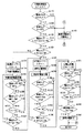
まず、図1は、本発明の実施例である充電器11とリチウムイオン電池13とを有して構成される充電システム1の概略構成図である。なお、図1では、充電器11の内部構成をブロック図として表している。
【0052】
リチウムイオン電池13は、定格出力電圧が3.7[V]の充放電可能な二次電池であり、充電器11から電力を受電するため、あるいは各種電気機器(図示省略)に対して電力を出力するための電池正極端子61および電池負極端子63を備えている。なお、本実施例のリチウムイオン電池13は、過放電状態または過充電状態に至るのを防止する保護回路は備えていない。
【0053】
また、リチウムイオン電池13の充電状態(換言すれば、充電残容量)が正常充電状態(過放電状態・過充電状態ではない状態)となる使用可能領域は、出力電圧が1.5〜4.25[V]となる領域であり、また、使用可能領域のうち通常使用領域(寿命低下が生じがたい領域)は、出力電圧が3.0〜4.2[V]となる領域である。
【0054】
なお、使用可能領域のうち、出力電圧が1.5〜2.45[V]となる領域においては、過放電状態に近い状態であり、大きな電流を通電すると、電池内部の構成材料(負極の集電体(Cu))が針状に析出する可能性がある。そのため、出力電圧が1.5〜2.45[V]である場合には、後述する予備充電(小電流の供給による充電)を行った後に通常充電を行うことで、リチウムイオン電池13の破裂・発火などの危険を回避することができる。
【0055】
リチウムイオン電池13は、使用可能領域に制御されることで、破裂・発火などの危険を伴うことなく安全に充電作業を行うことができると共に、充電作業後には電気機器に対して正常に電力供給を行うことができる。また、リチウムイオン電池13は、通常使用領域内となる環境下で使用することにより、寿命の低下を抑制できると共に、耐久性を向上させることができる。
【0056】
さらに、リチウムイオン電池13は、温度測定のためのサーミスタ60と、サーミスタ60での検出温度に応じた温度信号を出力するための温度信号出力端子65とを備えている。なお、サーミスタ60は、一端が電池負極端子63に接続されており、他端が温度信号出力端子65に接続されている。
【0057】
充電器11は、各種制御処理を実行する充電制御回路29を有する充電回路21と、外部の交流電源装置51から受電した交流電力を直流電力に変換するACアダプタ23と、各種情報を表示するための表示部25と、各種音声情報を出力するための音声出力部27と、リチウムイオン電池13の電池正極端子61に電気的に接続される充電器正極端子41と、リチウムイオン電池13の電池負極端子63に電気的に接続される充電器負極端子43と、リチウムイオン電池13の温度信号出力端子65に電気的に接続される温度信号入力端子45と、を備えて構成されている。
【0058】
充電器正極端子41および充電器負極端子43は、それぞれリチウムイオン電池13の電池正極端子61および電池負極端子63に接続可能な形状に形成されると共に、電池正極端子61および電池負極端子63に接続可能な位置に配置されている。温度信号入力端子45は、リチウムイオン電池13の温度信号出力端子65に接続可能な形状に形成されると共に、温度信号出力端子65に接続可能な位置に配置されている。
【0059】
ACアダプタ23は、直流電力を出力するための直流出力正極端子47および直流出力負極端子49を備えており、交流電源装置51から受電した交流電力を交流−直流変換して直流電力を生成した後、その直流電力を直流出力正極端子47および直流出力負極端子49から出力する。
【0060】
なお、充電器11においては、充電器正極端子41が、第1電力伝達経路53を介して直流出力正極端子47と電気的に接続されており、充電器負極端子43が、第2電力伝達経路55を介して直流出力負極端子49と電気的に接続されている。
【0061】
充電回路21は、上述した充電制御回路29の他に、第1電力伝達経路53の経路上に配置される通電制御用スイッチ31、抵抗素子33および整流用ダイオード35を備えると共に、充電器正極端子41および充電器負極端子43における電圧および電流を検出する電圧電流検出回路37を備えている。
【0062】
通電制御用スイッチ31は、一端が充電器正極端子41に接続され、他端が抵抗素子33を介して整流用ダイオード35のカソードに接続されており、充電制御回路29からの指令に基づき短絡状態または開放状態に駆動制御されることで、第1電力伝達経路53を通電状態または遮断状態に制御する。なお、通電制御用スイッチ31は、例えば、FETを用いて構成することができ、その場合には、寄生ダイオードにより電流通電が許容される電流方向が、充電器正極端子41から直流出力正極端子47(ACアダプタ23)に向かう方向となるように接続される。
【0063】
整流用ダイオード35は、アノードがACアダプタ23の直流出力正極端子47に接続されており、ACアダプタ23から充電器正極端子41に向かう電流を許容し、反対方向の電流通電を阻止する。
電圧電流検出回路37は、充電器正極端子41と充電器負極端子43との間に印加される電圧値、および充電器正極端子41と充電器負極端子43との間に流れる電流値を検出し、検出した電圧値(端子部両端電圧V_Bat)に応じた検出電圧信号と、検出した電流値(端子部間電流I_Bat)に応じた検出電流信号とを、充電制御回路29に対して出力する。
【0064】
充電制御回路29は、各種演算処理を行うCPU、記憶部としてのメモリ、外部回路との間で信号入出力を行う入出力部などを備えるマイクロコンピュータを主体に構成されており、充電作業に関する各種制御処理を実行することで、リチウムイオン電池13を充電するように充電器11の各部を制御する。なお、充電制御回路29は、通電制御用スイッチ31などに対して各種指令信号を出力するための各種信号経路(図示省略)が接続されており、また、ACアダプタ23から電力供給ライン(図示省略)を介して駆動用電力を受電している。
【0065】
そして、充電制御回路29は、通電制御用スイッチ31を短絡状態(オン状態)に駆動制御することで、充電器正極端子41および充電器負極端子43から外部に対する電圧値の出力状態を制御することができる。このとき、充電器11が出力する出力電圧値は一定値(例えば、4.2[V])であり、本実施例の充電器11は、リチウムイオン電池13に対する出力電圧値が一定電圧となる定電圧出力状態を実現でき、CV充電(定電圧充電)を実行することができる。
【0066】
なお、充電器11が一定電圧を出力する場合であっても、接続されたリチウムイオン電池13の両端電圧の影響を受けて、見かけ上の電圧値が低下することがあるが、リチウムイオン電池13の充電残容量が増加して電圧値は次第に上昇していき、最終的に目標充電電圧(4.2[V])に到達する。
【0067】
また、充電制御回路29は、例えば、通電制御用スイッチ31がFETで構成される場合には、FETゲート電圧を制御することで、充電器正極端子41および充電器負極端子43から外部に出力される電流値を一定値に制御することができる。例えば、充電制御回路29に外付けコンデンサ(図示省略)を設けて、その外付けコンデンサによってFETゲート電圧を一定値にすることで、充電器11から外部への出力電流値が一定値となる。そして、本実施例の充電器11は、外付けコンデンサ(図示省略)を備えており、リチウムイオン電池13に対する出力電流値が一定電流となる定電流出力状態を実現でき、CC充電(定電流充電)を実行することができる。
【0068】
なお、充電制御回路29は、リチウムイオン電池13の両端電圧が目標充電電圧に到達すると、両端電圧を監視しながら、目標充電電圧を超過しないようにFETゲート電圧を制御して、出力電流値(充電電流)を低下させていく。そして、出力電流値が充電終止電流以下まで減少すると充電を終了する。
【0069】
表示部25は、例えば、液晶パネルで構成することができ、充電回路21(詳細には、充電制御回路29)からの表示指令信号に基づき各種情報を表示する。音声出力部27は、例えば、スピーカで構成することができ、充電回路21(詳細には、充電制御回路29)からの音声出力指令信号に基づき各種音声情報を出力する。
【0070】
次に、充電制御回路29の内部で実行される充電制御処理について説明する。図2に、充電制御処理の処理内容を表すフローチャートを示す。
充電制御処理が開始されると、まず、S110(Sはステップを表す。以下同じ)では、リチウムイオン電池13が所定の電池配置部(図示省略)に配置されたか(セットされたか)否かを判断しており、肯定判定されるとS120に移行し、否定判定されるとS140に移行する。なお、充電器11の電池配置部には、配置されたリチウムイオン電池13によって押下される位置に機械式押ボタンスイッチ(図示省略)が備えられており、S110では、機械式押ボタンスイッチの状態に基づいて判定を行う。
【0071】
S110での判定は、機械式スイッチを用いる場合に限定されることはなく、例えば、充電器正極端子41と充電器負極端子43との間に印加されている端子部両端電圧V_Batに基づいて判定しても良く、端子部両端電圧V_Batが0[V]を超える場合に、リチウムイオン電池13が電池配置部(図示省略)に配置されたと判断しても良い。
【0072】
S110で肯定判定されてS120に移行すると、S120では、リチウムイオン電池13の温度が正常動作温度範囲(0〜45[℃])内であるか否かを判断しており、肯定判定される場合にはS130に移行し、否定判定される場合にはS140に移行する。S120では、サーミスタ60から温度信号出力端子65および温度信号入力端子45を介して充電制御回路29に入力される温度信号に基づき、リチウムイオン電池13の温度を検出する処理を行う。
【0073】
なお、サーミスタ60は温度に応じて電気抵抗値が変化する特性があるため、S120では、まず、リチウムイオン電池13から充電器11に入力される温度信号に基づきサーミスタ60の電気抵抗値を算出し、そのあと、サーミスタ60の電気抵抗値−温度特性に基づき定められたマップや計算式と、算出したサーミスタ60の電気抵抗値とに基づいて、リチウムイオン電池13の温度を検出することができる。
【0074】
S120で肯定判定されてS130に移行すると、S130では、充電器正極端子41と充電器負極端子43との間に印加されている端子部両端電圧V_Batが、使用可能領域(1.5〜4.25[V]の範囲)内であるか否かを判断しており、肯定判定されるとS150に移行し、否定判定されるとS140に移行する。つまり、S130では、充電器11の充電器側端子部(充電器正極端子41および充電器負極端子43)に対して、リチウムイオン電池13の電池側端子部(電池正極端子61および電池負極端子63)が接続されたか否かを判断している。
【0075】
なお、S130では、電圧電流検出回路37から入力される検出電圧信号に基づき端子部両端電圧V_Batを検出して、検出した端子部両端電圧V_Batを用いて判定を行う。また、S130では、本ステップの処理開始時に通電制御用スイッチ31が短絡状態である場合には、端子部両端電圧V_Batの検出前に、通電制御用スイッチ31を開放状態に制御して第1電力伝達経路53を遮断状態に設定することで、ACアダプタ23から充電器側端子部(充電器正極端子41および充電器負極端子43)に対する電力供給を停止させる。
【0076】
S110、S120、S130のいずれかで否定判定されてS140に移行すると、S140では、リチウムイオン電池13が異常状態であると判定し、リチウムイオン電池13の異常状態を示す警告表示を表示部25に表示すると共に、リチウムイオン電池13の異常状態を示す警報音を音声出力部27から出力する処理を行う。また、S140では、本ステップの処理開始時に通電制御用スイッチ31が短絡状態である場合には、通電制御用スイッチ31を開放状態に制御して第1電力伝達経路53を遮断状態に設定することで、ACアダプタ23から充電器側端子部(充電器正極端子41および充電器負極端子43)に対する電力供給を停止させる。
【0077】
なお、後述するS190、S200、S260、S270、S310、S320のいずれかのステップで否定判定された場合、あるいはS210、S280、S330のいずれかのステップで肯定判定された場合にも、S140の処理が実行される。
【0078】
また、S130で肯定判定されてS150に移行すると、S150では、S130にて検出した端子部両端電圧V_Batが、通常使用領域(2.45[V]以上の範囲)内であるか否かを判断しており、肯定判定されるとS230に移行し、否定判定されるとS160に移行する。
【0079】
S150で否定判定されてS160に移行すると、S160では、4時間の時間経過を計測するための4時間タイマでの時間カウント動作をスタートさせる処理を実行する。なお、S160では、予備充電作業の経過時間を計測するために、4時間タイマを始動させている。
【0080】
続くS170では、通電制御用スイッチ31を短絡状態に駆動制御する短絡指令信号を出力して、予備充電作業を開始する処理を行う。
次のS180では、充電器正極端子41および充電器負極端子43から外部への電流出力状態が予備用定電流出力状態となるように、通電制御用スイッチ31のFETゲート電圧を制御する処理を行う。これにより、充電器11は、微小な電流通電によりリチウムイオン電池13の充電を行う状態(予備用定電流充電状態)となる。
【0081】
なお、予備用定電流出力状態とは、単位時間当たりの電流供給量が予備充電許容範囲に含まれる状態で定電流を出力する状態を表す。また、予備充電許容範囲は、充電残容量が減少した状態(寿命低下領域(図4における第1電圧V1から第3電圧V3まで))のリチウムイオン電池13において、電流供給する際に破裂・発火などの危険が発生しない安全な電流供給量の範囲(例えば、1〜4[mA/H])が設定される。
【0082】
つまり、S150で否定判定される場合(端子部両端電圧V_Batが、例えば、2.45[V]未満である場合)には、リチウムイオン電池13は、使用可能領域ではあるものの充電残容量が少ない状態(過放電状態に近い状態)である。そのような状態のリチウムイオン電池13に対して大きな電流を供給すると、電池内部で溶け出した構成材料(負極の集電体(Cu))が針状に析出する可能性が高くなり、通電経路の短絡(ショート)などによって破裂・発火などの危険が生じる虞がある。そのため、大きい電流が流れる可能性が高い後述の通常充電作業(S230からS340までの処理)の前に、小さい電流の供給により充電を行う予備充電作業を行い、充電残容量を増加させることで、構成材料が針状に析出するのを防止して、リチウムイオン電池13の破裂・発火などの危険を回避するのである。
【0083】
続くS190では、S120と同様に、リチウムイオン電池13の温度が正常動作温度範囲(0〜45[℃])内であるか否かを判断しており、肯定判定される場合にはS200に移行し、否定判定される場合にはS140に移行する。
S190で肯定判定されてS200に移行すると、S200では、充電器正極端子41と充電器負極端子43との間に流れる端子部間電流I_Batが、予備充電用電流範囲(1〜4[mA]の範囲)内であるか否かを判断しており、肯定判定されるとS210に移行し、否定判定されるとS140に移行する。なお、S200では、電圧電流検出回路37から入力される検出電流信号に基づき端子部間電流I_Batを検出して判定を行う。
【0084】
S200で肯定判定されてS210に移行すると、S210では、4時間タイマによるカウント時間に基づき、予備充電作業の経過時間が4時間を超えたか否か(タイムアウトであるか否か)を判断しており、肯定判定されるとS140に移行し、否定判定されるとS220に移行する。
【0085】
S210で否定判定されてS220に移行すると、S220では、端子部両端電圧V_Batが通常使用領域(2.45[V]以上の範囲)内であるか否かを判断しており、肯定判定されるとS230に移行し、否定判定されると再びS180に移行する。なお、S220では、S130と同様に、電圧電流検出回路37から入力される検出電圧信号に基づき端子部両端電圧V_Batを検出して、検出した端子部両端電圧V_Batを用いて判定を行う。
【0086】
S150で肯定判定されるか、S220で肯定判定されてS230に移行すると、S230では、4時間の時間経過を計測する4時間タイマによる時間カウント動作をスタートさせる処理を実行する。なお、S230では、通常充電作業の経過時間を計測するために、4時間タイマを始動させている。
【0087】
続くS240では、通電制御用スイッチ31を短絡状態に駆動制御する短絡指令信号を出力して、通常充電作業を開始する処理を行う。
次のS250では、充電器正極端子41および充電器負極端子43から外部への電流出力状態が通常定電流出力状態となるように、通電制御用スイッチ31のゲート電圧を制御する処理を行う。これにより、充電器11は、通常の大きさの電流通電によりリチウムイオン電池13の充電を行う通常定電流充電状態となる。
【0088】
なお、通常定電流出力状態とは、単位時間当たりの電流供給量が通常充電許容範囲に含まれる状態で定電流を出力する状態を表す。また、通常充電許容範囲は、充電残容量が通常使用領域内となる状態のリチウムイオン電池13において、電流供給する際に破裂・発火などの危険が発生しない安全な電流供給量の範囲(例えば、15〜25[mA/H])が設定される。
【0089】
続くS260では、S120と同様に、リチウムイオン電池13の温度が正常動作温度範囲(0〜45[℃])内であるか否かを判断しており、肯定判定される場合にはS270に移行し、否定判定される場合にはS140に移行する。
S260で肯定判定されてS270に移行すると、S270では、端子部間電流I_Batが通常充電用電流範囲(15〜25[mA]の範囲)内であるか否かを判断しており、肯定判定されるとS280に移行し、否定判定されるとS140に移行する。なお、S270では、S200と同様に、電圧電流検出回路37から入力される検出電流信号に基づき端子部間電流I_Batを検出して判定を行う。
【0090】
S270で肯定判定されてS280に移行すると、S280では、4時間タイマによるカウント時間に基づき、通常充電作業の経過時間が4時間を超えたか否か(タイムアウトであるか否か)を判断しており、肯定判定されるとS140に移行し、否定判定されるとS290に移行する。
【0091】
S280で否定判定されてS290に移行すると、S290では、端子部両端電圧V_Batが寿命低下領域(4.20[V]以上の範囲)であるか否かを判断しており、肯定判定されるとS300に移行し、否定判定されると再びS250に移行する。なお、S290では、S130と同様に、電圧電流検出回路37から入力される検出電圧信号に基づき端子部両端電圧V_Batを検出して判定を行う。
【0092】
S290で肯定判定されてS300に移行すると、S300では、充電器正極端子41および充電器負極端子43から外部への電圧出力状態が通常定電圧出力状態となるように、通電制御用スイッチ31を短絡状態(オン状態)に制御する処理を行う。なお、通常定電圧出力状態とは、出力電流値の変動は許容して、出力電圧値が目標電圧値となるように定電圧を出力する状態を表す。また、目標電圧値は、リチウムイオン電池13の通常使用領域における最大電圧値(4.20[V])が設定される。
【0093】
続くS310では、S120と同様に、リチウムイオン電池13の温度が正常動作温度範囲(0〜45[℃])内であるか否かを判断しており、肯定判定される場合にはS320に移行し、否定判定される場合にはS140に移行する。
S310で肯定判定されてS320に移行すると、S320では、端子部両端電圧V_Batが目標電圧値(4.20[V])に等しいか否かを判断しており、肯定判定されるとS330に移行し、否定判定されるとS140に移行する。なお、S320では、S130と同様に、電圧電流検出回路37から入力される検出電圧信号に基づき端子部両端電圧V_Batを検出して判定を行う。
【0094】
S320で肯定判定されてS330に移行すると、S330では、S230で開始した4時間タイマによるカウント時間に基づき、通常充電作業の経過時間が4時間を超えたか否か(タイムアウトであるか否か)を判断しており、肯定判定されるとS140に移行し、否定判定されるとS340に移行する。
【0095】
S330で否定判定されてS340に移行すると、S340では、リチウムイオン電池13が満充電状態であるか否かを判断するために、端子部間電流I_Batが満充電判定基準範囲(2[mA]以下の範囲)内であるか否かを判断しており、肯定判定されるとS350に移行し、否定判定されると再びS300に移行する。なお、S340では、S200と同様に、電圧電流検出回路37から入力される検出電流信号に基づき端子部間電流I_Batを検出して、検出した端子部間電流I_Batを用いて判定を行う。
【0096】
S340で肯定判定されてS350に移行すると、S350では、通電制御用スイッチ31を開放状態に駆動制御する開放指令信号を出力して、通常充電作業を終了する処理を行う。
S140またはS350の処理が終了すると、充電制御処理は終了する。
【0097】
なお、本実施例においては、ACアダプタ23が特許請求の範囲に記載の電力供給手段に相当し、充電器正極端子41および充電器負極端子43が一対の充電器側端子部に相当し、充電回路21が充電状態制御手段に相当し、充電制御処理のS130および電圧電流検出回路37が接続状態判定手段に相当する。
【0098】
また、充電制御処理におけるS140、S200、S270、S340、S350が、特許請求の範囲における充電状態判定制御手段に相当し、充電制御処理のS140、表示部25および音声出力部27が電池異常報知手段に相当する。
さらに、リチウムイオン電池13の出力電圧の使用可能領域が、特許請求の範囲における正常電池出力電圧範囲に相当し、端子部間電流I_Batが充電時供給電流に相当し、S200の処理で用いる予備充電用電流範囲、S270の処理で用いる通常充電用電流範囲およびS340の処理で用いる満充電判定基準範囲がそれぞれ充電時正常通電電流範囲に相当する。
【0099】
以上説明したように、本実施例の充電システム1に備えられる充電器11は、外部から充電器正極端子41と充電器負極端子43との間に印加される端子部両端電圧V_Batが、リチウムイオン電池13の使用可能領域に含まれる場合には、充電器側端子部41,43と電池側端子部61.63とが接続状態であると判定し、通電制御用スイッチ31を短絡状態に設定して第1電力伝達経路53を通電状態に制御することで、リチウムイオン電池13に対して充電用の電力供給を行う。
【0100】
また、端子部両端電圧V_Batがリチウムイオン電池13の使用可能領域(1.5〜4.25[V])に含まれない場合には、充電器側端子部41,43と電池側端子部61.63とが未接続状態であると判定し、通電制御用スイッチ31を開放状態に駆動制御して第1電力伝達経路53を遮断状態に制御することで、充電器側端子部41,43から外部への電力供給を停止する。
【0101】
つまり、充電器11は、リチウムイオン電池13が接続されたか否かを判断するにあたり、内部のACアダプタ23から一対の充電器側端子部41,43に電力供給を行うのではなく、外部(実際には、リチウムイオン電池13)から一対の充電器側端子部41,43に供給される外部電力供給状態に基づいて、接続判断を行う。
【0102】
これにより、リチウムイオン電池13の接続判定を行うにあたり、リチウムイオン電池13への電圧印加が行われなくなり、接続判定を行う際にリチウムイオン電池13の充電量が増加するのを回避できる。
そして、S130では、判定基準値として、リチウムイオン電池13の使用可能領域を用いていることから、端子部両端電圧V_Batに基づいて、リチウムイオン電池13が接続されたか否かを判断することができる。
【0103】
さらに、S130では、過放電状態(出力電圧が1.5[V]未満)のリチウムイオン電池13が接続された場合には、端子部両端電圧V_Batが使用可能領域(1.5〜4.25[V])ではなく使用厳禁領域(1.5[V]未満)となるため否定判定することになり、そのリチウムイオン電池13に対する充電作業は実行しない。これにより、過放電状態のリチウムイオン電池に対して充電作業を行うのを防止することができ、過大電流の通電に伴う破裂・発火などの危険が生じるのを回避できる。
【0104】
よって、本実施例の充電器11は、電池側端子部61,63が充電器側端子部41,43に接続されたこと(すなわち、リチウムイオン電池13が充電器11に接続されたこと)を検出する機能を有しており、充電作業の煩雑さを解消できると共に、リチウムイオン電池13が過充電状態に至るのを防止できる。また、過放電状態のリチウムイオン電池13に対して充電用電力が供給されるのを防止できることから、発火・破裂などの危険を回避することができる。そして、充電器11を用いる場合には、リチウムイオン電池13の過充電を防止できるため、リチウムイオン電池13に保護回路(保護手段)を備える必要がなくなり、リチウムイオン電池13の小型化・薄型化が可能となる。
【0105】
次に、充電器11の充電制御回路29で実行される充電制御処理では、リチウムイオン電池13が接続されたと判定(S130で肯定判定)された場合において、リチウムイオン電池13に供給される端子部間電流I_Batが充電時正常通電電流範囲を逸脱する場合には、S140あるいはS350にて、通電制御用スイッチ31を開放状態に駆動制御して第1電力伝達経路53を遮断状態に制御している。なお、予備充電用電流範囲(S200)、通常充電用電流範囲(S270)および満充電判定基準範囲(S340)が、それぞれ充電時正常通電電流範囲である。
【0106】
このため、充電器11は、リチウムイオン電池13に供給される通電電流(充電時供給電流)が、充電時正常通電電流範囲の上限値を上回る場合には、充電器11からリチウムイオン電池13に対する電力供給を停止することができ、過大な電流通電に伴うリチウムイオン電池13の破損・発火などを防止できる。例えば、リチウムイオン電池13が、何らかの原因で異常状態となり、充電作業時に過大電流が流れるような場合においても、充電器11を用いていれば、過大電流の通電に伴うリチウムイオン電池13の破裂・発火などの危険を回避できる。
【0107】
また、充電器11は、リチウムイオン電池13への充電時供給電流が充電時正常通電電流範囲の下限値を下回る場合には、充電器11からリチウムイオン電池13に対する電力供給を停止することができる。これにより、リチウムイオン電池13が満充電状態になり電流値が減少した場合に、電力供給を停止できるため、満充電状態のリチウムイオン電池13に対して充電用の電力が無駄に供給されるのを防止できる。あるいは、リチウムイオン電池13が何らかの原因で異常状態であるために充電時供給電流が過小になる場合にも、電力供給を停止できるため、異常状態のリチウムイオン電池13に対する充電用電力の供給が原因で破裂・発火などの危険が発生するのを防止できる。
【0108】
よって、本実施例の充電器11によれば、リチウムイオン電池13の破裂・発火などの危険を回避することができ、また、無駄な充電用電力の消費を抑えることで、効率よくリチウムイオン電池13の充電を行うことができる。
次に、充電器11は、リチウムイオン電池13が電池配置部に配置されたことを検出した後、通電制御用スイッチ31を開放状態に駆動制御して、第1電力伝達経路53を遮断状態に制御する場合には、表示部25にリチウムイオン電池13の異常状態を示す警告表示を行うと共に、音声出力部27からリチウムイオン電池13の異常状態を示す警報音を出力する。このように、リチウムイオン電池13が異常状態であることを報知することで、充電器11が故障していると誤って認識されるのを防止できる。
【0109】
なお、耐用年数(寿命)を過ぎたリチウムイオン電池13は、異常状態となることから、この充電器11を用いることで、リチウムイオン電池13が耐用年数(寿命)を過ぎているか、換言すれば、リチウムイオン電池13を廃棄するか否かを判断するために用いることもできる。
【0110】
また、本実施例の充電器11は、保護回路を有さないリチウムイオン電池13であっても過充電状態になるのを防止しつつ充電作業を行うことができ、また、過放電状態のリチウムイオン電池13に対する電力供給を停止できる。このため、充電対象であるリチウムイオン電池13は、小型化・薄型化を図ることができると共に、過放電状態での充電による危険を回避することができ、また、過充電状態になるのを防止することができる。
【0111】
次に、充電器11を用いたリチウムイオン電池13の充電作業が可能であることを確認するために実施した測定結果について説明する。なお、本測定では、充電作業の時間経過に伴う電池両端電圧(リチウムイオン電池13の両端電圧)の変化、および時間経過に伴う通電電流(充電器11からリチウムイオン電池13への出力電流)の変化をそれぞれ測定した。図3に、横軸を充電時間(経過時間)とし、縦軸を電池両端電圧および通電電流とする座標平面に対して測定結果を表した説明図を示す。
【0112】
図3に示すように、充電時間が0分から約92分までの区間では、通電電流が一定となる通常定電流出力状態での充電作業(通常充電作業)が行われており、時間経過と共に電池両端電圧が増加している。また、充電時間が約92分から約152分までの区間では、印加電圧が一定となる通常定電圧出力状態での充電作業(通常充電作業)が行われており、リチウムイオン電池13の充電残容量が増加することに伴い、通電電流が低下している。
【0113】
そして、充電時間が約152分になると、通電電流が満充電判定基準値(本測定では、2[mA]に設定されている)以下となり、リチウムイオン電池13が満充電状態に到達したと判定されて、充電器11は、リチウムイオン電池13への電力供給を停止して充電作業を終了する。
【0114】
つまり、この測定結果によれば、充電器11を用いた充電作業においては、リチウムイオン電池13が過充電状態になることなく満充電状態まで適切に充電することができ、また、通電電流値が一定範囲内に抑制できるため、過大電流による破裂・発火などの危険が生じるのを防止できることが判る。また、リチウムイオン電池13の充電作業を開始できていることから、リチウムイオン電池13の出力電力を用いて、リチウムイオン電池13の接続を確認できることが判る。
【0115】
以上、本発明の実施例について説明したが、本発明は、こうした実施例に限定されることはなく、種々の態様をとることができる。
例えば、上記実施例では、充電制御処理のS130にてリチウムイオン電池13(二次電池)が接続されたか否かを判断するにあたり、端子部両端電圧V_Batを用いたが、充電器正極端子41と充電器負極端子43との間に通電される端子部間電流I_Batを用いても良い。つまり、端子部間電流I_Batが使用可能領域(正常電池出力電流範囲)に含まれるか否かに基づいて、二次電池が接続されたか否かを判定しても良い。
【0116】
また、端子部両端電圧V_Batおよび端子部間電流I_Batの両方を用いて二次電池が接続状態であるか否かを判定してもよく、その場合には、端子部両端電圧V_Batが正常電池出力電圧範囲に含まれ、かつ、端子部間電流I_Batが正常電池出力電流範囲に含まれる場合に、充電器側端子部と電池側端子部とが接続状態であると判定するとよい。このように端子部両端電圧V_Batおよび端子部間電流I_Batの両方を用いて判定を行うことで、充電器側端子部と電池側端子部とが接続状態であること(充電器に二次電池が電気的に接続されたこと)を、さらに精度良く判定することができる。
【0117】
さらに、リチウムイオン電池13が異常状態であるために電流供給を停止する場合に、S140では、表示部25への警告表示および音声出力部27からの警報音出力の2つの報知処理を実行するが、必要に応じて、警告表示または警報音出力のいずれか一方のみを行うようにしてもよい。
【0118】
また、充電制御処理における各数値は、実施例としての一例を示しただけであり、本発明および本発明方法を実施する際には、上記数値に限定されることはなく、充電対象の二次電池の種類、容量や用途などに応じて適切な数値を設定することができることはいうまでもない。
【図面の簡単な説明】
【図1】充電器とリチウムイオン電池とを有して構成される充電システムの概略構成図である。
【図2】充電制御処理の処理内容を表すフローチャートである。
【図3】充電作業の時間経過に伴う電池両端電圧の変化、および時間経過に伴う通電電流の変化をそれぞれ測定した測定結果を示す説明図である。
【図4】二次電池の出力電圧を基準として、二次電池の使用可能領域および使用厳禁領域を表した説明図である。
【図5】二次電池とは別体に構成される充電器と、二次電池とを有して構成される従来型充電システムの概略構成図である。
【図6】電池パックと充電器とを有して構成される第2従来型充電システムの概略構成図である。
【符号の説明】
1…充電システム、11…充電器、13…リチウムイオン電池、21…充電回路、23…ACアダプタ、25…表示部、27…音声出力部、29…充電制御回路、31…通電制御用スイッチ、37…電圧電流検出回路、41…充電器正極端子、43…充電器負極端子、53…第1電力伝達経路、55…第2電力伝達経路、61…電池正極端子、63…電池負極端子。[0001]
TECHNICAL FIELD OF THE INVENTION
The present invention relates to a charger for charging a secondary battery by supplying power from a pair of charger-side terminals to a battery-side terminal of a secondary battery, and a secondary battery using such a charger. To a charging method for charging the battery.
[0002]
[Prior art]
2. Description of the Related Art Conventionally, a secondary battery configured to be chargeable and dischargeable, and a charger that charges the secondary battery by supplying power to the secondary battery are known.
When charging the secondary battery, when the power supply to the secondary battery is excessive and the battery is overcharged, there is a risk that the secondary battery may burst or ignite.
[0003]
In addition, as for the secondary battery in which the stored power is excessively discharged and is in an overdischarged state, a part of the constituent material (a current collector (Cu) of the negative electrode) inside the battery may be melted, and may be melted. When charging the secondary battery, the constituent material may precipitate in a needle shape. At this time, the needle-shaped constituent material may short-circuit the current-carrying path, and there is a risk that the secondary battery may burst or ignite with the short-circuit of the current-carrying path due to the needle-shaped constituent material. .
[0004]
In order to solve such a problem, a charging / discharging device for preventing a secondary battery from being in an overcharged state or an overdischarged state has been proposed (see Patent Document 1). This device bypasses the charging power to the secondary battery by the bypass circuit when the secondary battery is fully charged at the time of charging work, so that the secondary battery can be prevented from being overcharged. When the secondary battery approaches the over-discharge state, an over-discharge alarm is sent out, so that the over-discharge state of the secondary battery can be prevented.
[0005]
In other words, the charge state of the secondary battery (in other words, the remaining charge capacity) is controlled to be in a usable area where the battery is in a normal charge state (an overdischarge state or a state that is not an overcharge state), and the charge of the secondary battery This prevents the state from reaching a strictly prohibited area such as an overcharged state or an overdischarged state. Rechargeable batteries controlled in the usable area can be charged safely without danger such as explosion or ignition, and power supply to electrical equipment should be performed normally after charging. Can be.
[0006]
Here, FIG. 4 is an explanatory diagram showing a usable area and a strictly prohibited area of use of the secondary battery with reference to the output voltage. In FIG. 4, the vertical axis represents the output voltage of the secondary battery, and represents an area in which the voltage value increases as the position goes upward in the figure. An example of the secondary battery is a battery pack having a protection circuit described later. And each area is shown. Further, the first voltage V1 is greater than 0 [V], and the voltage value increases in order from the first voltage V1, as the voltage becomes the second voltage V2, the third voltage V3, the fourth voltage V4, and the fifth voltage V5. .
[0007]
In FIG. 4, a strictly prohibited area from 0 [V] to the first voltage V1 indicates an overdischarge state, and a strictly prohibited area in a region higher than the fifth voltage V5 indicates an overcharged state. From this, it is possible to prevent the rechargeable battery from being overcharged by setting the charger operation area of the charger, the operation area of the protection circuit, and the equipment use area of the electric device so as not to include the strictly prohibited use area. It is possible to prevent the charging of the secondary battery in the overdischarged state.
[0008]
Further, even when the secondary battery is in the usable area, when the remaining charge capacity is large or small, the durability (lifetime) is adversely affected. Therefore, the rechargeable battery is charged from the third voltage V3 to the fourth voltage V4. While the region is a normal use region that has little adverse effect on durability, the region from the first voltage V1 to the third voltage V3 and the region from the fourth voltage V4 to the fifth voltage V5 are less durable. This is a life-decreasing area in which the adverse effect of the above is great. For this reason, the durability of the secondary battery can be improved by setting the charger operation region and the device use region in consideration of the life reduction region.
[0009]
By the way, the charger is not limited to one configured integrally with the secondary battery as in the device described in the above-mentioned patent document, and may be configured separately from the secondary battery. FIG. 5 is a schematic configuration diagram of a charging system 101 (hereinafter, also referred to as a conventional charging system 101) including a
[0010]
The
[0011]
The
[0012]
According to the
[0013]
Note that this
[0014]
[Patent Document 1]
JP-A-2002-223525 (Claim 1, FIG. 1, paragraph [0009], paragraphs [0016] to [0017])
[0015]
[Problems to be solved by the invention]
However, in the charger 103 (hereinafter, also referred to as a conventional charger 103) configured to apply a connection confirmation voltage from the internal power supply source to the pair of charger-side terminals, the connection confirmation of the secondary battery is performed. The repetition of the operation (operation of applying the connection confirmation voltage) may cause the
[0016]
In other words, each time the
[0017]
However, depending on the use of the secondary battery, after detaching from the charger, the battery may be connected to the charger again with little power consumption, and the charger in such a low power consumption state If connection to and disconnection from the battery is frequently repeated, the secondary battery may reach an overcharged state.
[0018]
On the other hand, the device described in the above patent document can prevent the secondary battery from reaching an overcharged state during the charging operation, but the secondary battery that is executed before the charging operation can be prevented. It is not possible to prevent overcharging due to the connection confirmation operation.
Further, the
[0019]
In order to solve such a problem, a protection circuit-integrated secondary battery (a so-called battery pack) in which a secondary battery main body for storing power and a protection circuit for preventing overdischarge or overcharge are integrally provided. ) May be used instead of the
[0020]
FIG. 6 shows a schematic configuration diagram of a second
[0021]
The
In the
[0022]
As described above, the battery pack having the protection circuit has an advantage that safety can be improved because the secondary battery body can be prevented from being in an overcharged state or an overdischarged state.
However, in recent years, demand for miniaturization and thinning of secondary batteries has been increasing due to diversification of applications of secondary batteries, whereas secondary batteries having a protection circuit (in detail, battery packs) ) Has a problem that it cannot meet the demand for miniaturization and thickness reduction because the volume is increased by the provision of the protection circuit. For this reason, in applications where miniaturization and thinning are prioritized, it is necessary to use a secondary battery having no protection circuit.However, the possibility of an overcharged state or an overdischarged state increases. There is a problem that the life of the secondary battery is shortened.
[0023]
Therefore, the present invention has been made in view of such a problem, and in charging the secondary battery, while having a function of detecting the connection of the secondary battery, while enabling the size and thickness of the secondary battery, It is another object of the present invention to provide a charger and a charging method capable of preventing a secondary battery from reaching an overcharged state.
[0024]
[Means for Solving the Problems]
A first aspect of the present invention that has been made to achieve this object is a power supply unit that supplies charging power for charging a secondary battery, and a power supply unit that is electrically connected to the power supply unit via a power transmission path. In addition, a pair of charger-side terminals arranged so as to be electrically connectable to a pair of battery-side terminals provided in the secondary battery, and the charger-side terminals and the battery-side terminals are in a connected state. In the case, a charging state control unit that controls the power transmission path to an energized state, and controls the power transmission path to a cutoff state when the charger-side terminal unit and the battery-side terminal unit are not connected, A charger for charging a secondary battery, wherein the external power supply state, which is a supply state of power supplied from the outside to a pair of charger-side terminals, is a secondary battery in a normal operation. Power supply status is the same as the normal battery power supply status If the external power supply state is different from the normal battery power supply state, it is determined that the charger side terminal section and the battery side terminal section are connected. A connection state determination unit that determines that the unit is in a non-connection state, wherein the charge state control unit controls a state of the power transmission path based on a determination result by the connection state determination unit.
[0025]
According to another aspect of the present invention, there is provided a method of charging a battery including a pair of charger-side terminals disposed so as to be electrically connectable to a pair of battery-side terminals provided in a secondary battery. A charging method for charging a secondary battery using a charger, wherein an external power supply state, which is a supply state of power supplied to a pair of charger-side terminals from outside, is a secondary power supply in a normal operation. If the normal battery power supply state, which is the state of power supply by the battery, is equal to the battery side terminal section, it is determined that the charger side terminal section and the battery side terminal section are in a connected state, and the battery side is connected to the battery side. When power is supplied to the terminal section and the external power supply state is different from the normal battery power supply state, it is determined that the charger side terminal section and the battery side terminal section are not connected, and the charger side terminal is Do not supply power to the battery terminal from the And it features.
[0026]
That is, in the charger and the charging method of the present invention, in determining whether or not the secondary battery is connected, power is not supplied from the internal power supply unit to the pair of charger-side terminals, but is supplied to the external unit. It is determined whether the battery-side terminal of the secondary battery is connected to the charger-side terminal based on the external power supply state supplied to the pair of charger-side terminals from.
[0027]
Thus, it is possible to prevent the charge amount of the secondary battery from increasing due to the application of the connection confirmation voltage to the secondary battery.
When the battery-side terminal of the secondary battery is connected to the charger-side terminal, the output power of the secondary battery is supplied to the charger. If the state becomes equal to the normal battery power supply state by the secondary battery, it can be determined that the charger-side terminal and the battery-side terminal are in a connected state. Here, the secondary battery at the time of normal operation refers to, for example, a secondary battery that is included in the usable area described above.
[0028]
In the present invention, since the secondary battery supplies power at the time of connection determination, when a secondary battery in a discharged state is connected, the remaining charge capacity of the secondary battery is further reduced. However, since the power supply state of such an over-discharged secondary battery is different from the normal battery power supply state, it is determined that the secondary battery is not connected. No power supply for charging is performed. Thus, charging of the over-discharged secondary battery can be prevented, and danger such as explosion or fire associated with charging the over-discharged secondary battery can be avoided.
[0029]
Therefore, according to the charger and the charging method of the present invention, a function of detecting that the battery-side terminal is connected to the charger-side terminal (that is, connection of the secondary battery) is provided. Can be eliminated, and the secondary battery can be prevented from reaching an overcharged state. In addition, it is possible to prevent the charging power from being supplied to the over-discharged secondary battery, and it is possible to avoid danger such as ignition or explosion. In addition, since the secondary battery can be prevented from being overcharged, the secondary battery does not need to be provided with a protection circuit (protection means), and the size and thickness of the secondary battery can be reduced.
[0030]
Next, the above-described charger has a normal battery output in which a voltage applied across the terminal portion, which is a voltage applied between the pair of charger-side terminal portions from the outside, is a voltage range that the secondary battery outputs during normal operation. If it is included in the voltage range, it is determined that the charger-side terminal portion and the battery-side terminal portion are in a connected state. The connection state determination means may be configured to determine that the terminal section and the battery-side terminal section are not connected.
[0031]
Similarly, in the charging method described above, the voltage across the terminal, which is a voltage applied between the pair of charger-side terminals from the outside, is within the voltage range output by the secondary battery during normal operation. If it is included in the battery output voltage range, it is determined that the charger-side terminal and the battery-side terminal are in a connected state, and power is supplied from the charger-side terminal to the battery-side terminal. If the voltage at both ends is not included in the normal battery output voltage range, it is determined that the charger-side terminal and the battery-side terminal are not connected, and the power from the charger-side terminal to the battery-side terminal is determined. Supply can be avoided.
[0032]
In other words, the voltage between the terminal portions, which is a voltage applied between the pair of charger-side terminal portions from the outside, can be used as an index for determining the external power supply state, and the voltage between the terminal portions is within the normal battery output voltage range. , It can be determined that the charger-side terminal and the battery-side terminal are in a connected state.
[0033]
Here, the normal battery output voltage range refers to an area corresponding to the above-described usable area in the output voltage fluctuation range of the secondary battery.
Therefore, according to the present invention, it is possible to determine that the secondary battery is connected based on the voltage between the terminal portions, so that it is possible to reduce the complexity of the charging operation and to prevent the secondary battery from being overcharged. Can be prevented.
[0034]
Since the normal battery output voltage range varies depending on the type of the secondary battery, means for updating the normal battery output voltage range may be provided according to the type of the secondary battery to be charged. As a result, a charger and a charging method that can support various secondary batteries can be realized.
[0035]
Furthermore, in the above-described charger, the terminal-to-terminal current, which is a current that flows between the pair of charger-side terminals from outside, is a normal battery output current that is a current range output by the secondary battery during normal operation. If it is included in the range, it is determined that the charger-side terminal portion and the battery-side terminal portion are in a connected state, and if the current between the terminal portions is not included in the normal battery output current range, the charger-side terminal portion is determined. The connection state determination means may be configured to determine that the unit and the battery side terminal unit are not connected.
[0036]
Similarly, in the charging method described above, the terminal-to-terminal current, which is a current passed between the pair of charger-side terminals from the outside, is a normal battery output that is a current range output by the secondary battery during normal operation. If it is included in the current range, it is determined that the charger-side terminal and the battery-side terminal are in a connected state, power is supplied from the charger-side terminal to the battery-side terminal, and the terminal-to-terminal current is supplied. Is not included in the normal battery output current range, it is determined that the charger-side terminal and the battery-side terminal are not connected, and power supply from the charger-side terminal to the battery-side terminal is performed. It may not be performed.
[0037]
That is, the terminal-to-terminal current, which is a current that flows between the pair of charger-side terminals from the outside, can be used as an index for determining the external power supply state. , It can be determined that the charger-side terminal and the battery-side terminal are in a connected state.
[0038]
Therefore, according to the present invention, it is possible to determine that the secondary battery is connected based on the voltage between the terminal portions, so that it is possible to reduce the complexity of the charging operation and to prevent the secondary battery from being overcharged. Can be prevented.
When judging whether or not the charger-side terminal and the battery-side terminal are in a connected state by using both the voltage between the terminals and the current between the terminals, the voltage between the terminals is normal battery. When the output voltage range and the inter-terminal current are included in the normal battery output current range, it may be determined that the charger-side terminal and the battery-side terminal are in a connected state. By making a determination using both the voltage across the terminal and the current between the terminals in this manner, it is possible to more accurately and reliably determine that the charger-side terminal and the battery-side terminal are in a connected state. Can be.
[0039]
Further, since the normal battery output current range varies depending on the type of the secondary battery, a means for updating the normal battery output current range may be provided according to the type of the secondary battery to be charged. As a result, a charger and a charging method that can support various secondary batteries can be realized.
[0040]
Next, the above-described charger is supplied from the power supply unit to the secondary battery when the connection state determination unit determines that the charger side terminal unit and the battery side terminal unit are in the connected state. Charge state determination control means for controlling a power transmission path to a cut-off state when a supply current during charging deviates from a normal supply current range during charging, which is a current range supplied to the secondary battery during normal charging work. May be provided.
[0041]
Similarly, according to the charging method described above (any one of claims 8 to 10), after the power supply from the charger-side terminal to the battery-side terminal is started, the charging method starts. If the charging supply current supplied to the rechargeable battery from the unit terminal deviates from the normal charging current range, which is the range of current supplied to the rechargeable battery during normal charging work, Power supply from the side terminal to the battery side terminal may be stopped.
[0042]
According to this charger or charging method, when the supply current during charging excessively increases and exceeds the upper limit value of the normal conduction current range during charging of the secondary battery, the power supply from the charger to the secondary battery is stopped. By doing so, it is possible to prevent the secondary battery from being damaged or fired due to excessive current flow. For example, an excessive current may flow during charging work for a secondary battery that has an abnormality due to some factor.However, using this charger or charging method may reduce the risk of explosion or ignition due to the application of excessive current. Can be avoided.
[0043]
Further, by using the charger or the charging method of the present invention, even when the supply current at the time of charging is significantly reduced and becomes lower than the lower limit value of the normal energizing current range at the time of charging the secondary battery, the secondary battery is charged from the charger. Can be stopped. For example, when the secondary battery is fully charged and the current value is reduced, the power supply can be stopped. Therefore, it is possible to prevent unnecessary supply of charging power to the fully charged secondary battery. . Alternatively, even if the supply current during charging becomes too small due to an abnormal state of the secondary battery for some reason, the power supply can be stopped. It is possible to prevent the danger such as rupture or ignition of the secondary battery from occurring.
[0044]
Therefore, according to the present invention, it is possible to avoid dangers such as rupture and ignition of the secondary battery, and to efficiently charge the secondary battery by suppressing wasteful charging power consumption. it can.
According to the present invention, when the connected secondary battery is in an abnormal state, it is determined that the charger-side terminal portion and the battery-side terminal portion are not connected. No charging power is supplied to the secondary battery. Further, even if it is determined that the charger-side terminal portion and the battery-side terminal portion are in a connected state, if the charging supply current deviates from the normal charging current range during charging of the secondary battery, the charger-side terminal The power supply from the unit to the battery side terminal unit is stopped.
[0045]
When the power supply is stopped in this way, the user of the charger may erroneously recognize that charging power supply to the secondary battery is not performed due to a failure of the charger.
Therefore, as described above, when the power transmission path is controlled to be in the cutoff state, it is preferable to include a battery abnormality notification unit that reports that the secondary battery is in an abnormal state.
[0046]
Similarly, as described above, when power is not supplied from the charger-side terminal to the battery-side terminal, it may be notified that the secondary battery is in an abnormal state.
That is, by reporting that the secondary battery is in an abnormal state, it is possible to prevent the charger from being erroneously recognized as having failed. This charger or charging method can also be used to determine whether to dispose of the secondary battery.
[0047]
In addition, as the notification method, for example, a notification method using a sound, a buzzer, or the like, a notification method using character display, or the like can be employed.
By the way, as described above, the secondary battery includes a protection circuit-integrated secondary battery (a so-called battery pack) in which a secondary battery body and a protection circuit are integrally provided. Since overdischarge can be prevented, there is an advantage that safety is improved. However, since the battery pack includes components such as a protection circuit and a thermistor, it has a disadvantage that the volume is large, and thus it is difficult to use the battery pack in applications where miniaturization and thinning are prioritized. Therefore, in applications where miniaturization and thinning are prioritized, a secondary battery without a protection circuit will be used, but the possibility of an overcharged or overdischarged state increases, and the secondary battery becomes The problem is that the life of the device is shortened.
[0048]
Therefore, in the above-described charger and charging method, the secondary battery to be charged may be a secondary battery having no protection circuit for preventing overdischarge or overcharge.
That is, the charger of the present invention and the charging method of the present invention can prevent the secondary battery from reaching an overcharged state, and can stop power supply to the overcharged secondary battery. .
[0049]
For this reason, since the secondary battery to be charged is a secondary battery that does not have a protection circuit for preventing overdischarge or overcharge, there is a danger of reaching an overcharged state and a secondary battery in an overdischarged state. The effects of the present invention, such as avoiding the danger associated with charging the battery, can be further exhibited. Further, according to the charger of the present invention and the charging method of the present invention, the size and thickness of the secondary battery can be reduced.
[0050]
Note that a lithium ion secondary battery is an example of a secondary battery in which the durability (shortening of life) due to overcharge / overdischarge is likely to occur.
For this reason, in the above-mentioned charger and the above-mentioned charging method, since the secondary battery to be charged is a lithium-ion secondary battery, there is a danger of reaching an overcharged state or a secondary battery in an overdischarged state. Thus, the effects of the present invention and the method of the present invention, such as avoiding the danger associated with charging, can be further exerted.
[0051]
BEST MODE FOR CARRYING OUT THE INVENTION
Hereinafter, embodiments of the present invention will be described with reference to the drawings.
First, FIG. 1 is a schematic configuration diagram of a charging system 1 including a charger 11 and a
[0052]
The
[0053]
The usable region where the charge state (in other words, the remaining charge capacity) of the lithium-
[0054]
In the usable region, a region where the output voltage is 1.5 to 2.45 [V] is in a state close to an overdischarged state. The current collector (Cu) may be deposited in a needle shape. Therefore, when the output voltage is 1.5 to 2.45 [V], the
[0055]
By controlling the
[0056]
Further, the
[0057]
The charger 11 includes a charging
[0058]
The charger positive terminal 41 and the charger
[0059]
The
[0060]
In the charger 11, the charger positive terminal 41 is electrically connected to the DC output
[0061]
The charging
[0062]
The
[0063]
The rectifying
The voltage / current detection circuit 37 detects a voltage value applied between the charger positive terminal 41 and the charger
[0064]
The
[0065]
Then, the
[0066]
Even when the charger 11 outputs a constant voltage, the apparent voltage value may decrease due to the influence of the voltage between both ends of the connected
[0067]
In addition, for example, when the
[0068]
When the voltage across the
[0069]
The
[0070]
Next, a charge control process executed inside the
When the charge control process is started, first, in S110 (S represents a step; the same applies hereinafter), it is determined whether or not the
[0071]
The determination in S110 is not limited to the case where a mechanical switch is used, and is determined based on, for example, a terminal portion voltage V_Bat applied between the charger positive terminal 41 and the charger
[0072]
When the affirmative determination is made in S110 and the process proceeds to S120, it is determined in S120 whether or not the temperature of the
[0073]
Since the
[0074]
When the determination at S120 is affirmative and the process proceeds to S130, at S130, the voltage V_Bat across the terminal applied between the charger positive terminal 41 and the charger
[0075]
In S130, the terminal voltage V_Bat is detected based on the detected voltage signal input from the voltage / current detection circuit 37, and the determination is performed using the detected terminal voltage V_Bat. In S130, if the
[0076]
When a negative determination is made in any of S110, S120, and S130 and the process proceeds to S140, in S140, it is determined that the
[0077]
The processing of S140 is also performed when a negative determination is made in any of steps S190, S200, S260, S270, S310, and S320, or when an affirmative determination is made in any of steps S210, S280, and S330. Is executed.
[0078]
When the determination at S130 is affirmative, and the process proceeds to S150, it is determined at S150 whether or not the voltage V_Bat across the terminal detected at S130 is within the normal use area (range of 2.45 [V] or more). When the determination is affirmative, the process proceeds to S230, and when the determination is negative, the process proceeds to S160.
[0079]
When a negative determination is made in S150 and the process proceeds to S160, a process of starting a time counting operation with a four-hour timer for measuring the elapse of four hours is executed in S160. In S160, a four-hour timer is started to measure the elapsed time of the pre-charging operation.
[0080]
In S170, a short-circuit command signal for controlling the
In the next S180, a process of controlling the FET gate voltage of the
[0081]
Note that the standby constant current output state indicates a state in which a constant current is output in a state where the current supply amount per unit time is included in the preliminary charge allowable range. Further, the pre-charge allowable range indicates that the
[0082]
That is, when a negative determination is made in S150 (when the voltage V_Bat across the terminal portion is, for example, less than 2.45 [V]), the remaining charge capacity of the
[0083]
At S190, similarly to S120, it is determined whether the temperature of the
When the determination at S190 is affirmative and the process proceeds to S200, at S200, the terminal-to-terminal current I_Bat flowing between the charger positive terminal 41 and the charger
[0084]
When the affirmative determination is made in S200 and the process proceeds to S210, it is determined in S210 whether or not the elapsed time of the pre-charging operation has exceeded 4 hours (whether or not a timeout has occurred) based on the count time of the 4-hour timer. If the determination is affirmative, the process proceeds to S140, and if the determination is negative, the process proceeds to S220.
[0085]
When a negative determination is made in S210 and the process proceeds to S220, in S220, it is determined whether or not the voltage V_Bat across the terminal is within the normal use region (range of 2.45 [V] or more), and an affirmative determination is made. Then, the process returns to S230. If a negative determination is made, the process returns to S180. In S220, as in S130, the terminal voltage V_Bat is detected based on the detection voltage signal input from the voltage / current detection circuit 37, and the determination is performed using the detected terminal voltage V_Bat.
[0086]
When an affirmative determination is made in S150 or an affirmative determination is made in S220 and the process proceeds to S230, in S230, a process of starting a time counting operation by a four-hour timer that measures the elapse of four hours is executed. In S230, a 4-hour timer is started to measure the elapsed time of the normal charging operation.
[0087]
At S240, a short-circuit command signal for driving and controlling the power
In the next step S250, a process of controlling the gate voltage of the
[0088]
Note that the normal constant current output state indicates a state in which a constant current is output in a state where the current supply amount per unit time is within the normal charge allowable range. Further, the normal charge allowable range is a range of a safe current supply amount that does not cause danger such as rupture or ignition when supplying current in the
[0089]
At S260, similarly to S120, it is determined whether or not the temperature of the
When the affirmative determination is made in S260 and the process proceeds to S270, in S270, it is determined whether or not the inter-terminal section current I_Bat is within the normal charging current range (range of 15 to 25 [mA]). Then, the process proceeds to S280, and if a negative determination is made, the process proceeds to S140. In S270, similarly to S200, the determination is made by detecting the terminal-to-terminal current I_Bat based on the detection current signal input from the voltage / current detection circuit 37.
[0090]
When the determination in S270 is affirmative and the process proceeds to S280, it is determined in S280 whether or not the elapsed time of the normal charging operation has exceeded 4 hours (whether or not a timeout has occurred) based on the count time of the 4-hour timer. If an affirmative determination is made, the process proceeds to S140, and if a negative determination is made, the process proceeds to S290.
[0091]
When a negative determination is made in S280 and the process proceeds to S290, in S290, it is determined whether or not the voltage V_Bat across the terminal is in the life reduction region (a range of 4.20 [V] or more). The process proceeds to S300, and if a negative determination is made, the process proceeds to S250 again. In S290, as in S130, the terminal voltage V_Bat is detected based on the detection voltage signal input from the voltage / current detection circuit 37, and the determination is performed.
[0092]
When the determination in S290 is affirmative and the process proceeds to S300, the
[0093]
At S310, similarly to S120, it is determined whether or not the temperature of the
When the affirmative determination is made in S310 and the process proceeds to S320, in S320, it is determined whether or not the voltage V_Bat across the terminal is equal to the target voltage value (4.20 [V]). If the affirmative determination is made, the process proceeds to S330. If a negative determination is made, the process proceeds to S140. In step S320, as in step S130, the terminal voltage V_Bat is detected based on the detection voltage signal input from the voltage / current detection circuit 37, and the determination is performed.
[0094]
When the affirmative determination is made in S320 and the process proceeds to S330, in S330, based on the count time by the 4-hour timer started in S230, it is determined whether or not the elapsed time of the normal charging operation has exceeded 4 hours (whether or not a timeout has occurred). If the determination is affirmative, the process proceeds to S140, and if the determination is negative, the process proceeds to S340.
[0095]
When a negative determination is made in S330 and the process proceeds to S340, in S340, in order to determine whether or not the lithium-
[0096]
When the determination at S340 is affirmative and the process proceeds to S350, at S350, an open command signal for driving and controlling the
When the processing in S140 or S350 ends, the charging control processing ends.
[0097]
In this embodiment, the
[0098]
In addition, S140, S200, S270, S340, and S350 in the charge control process correspond to a charge state determination control unit in the claims, and S140 of the charge control process, the
Further, the usable area of the output voltage of the
[0099]
As described above, the charger 11 provided in the charging system 1 of the present embodiment is configured such that the voltage V_Bat across the terminal portion applied between the charger positive terminal 41 and the charger negative terminal 43 from the outside is lithium ion. When the
[0100]
When the voltage V_Bat across the terminals is not included in the usable area (1.5 to 4.25 [V]) of the
[0101]
That is, the charger 11 does not supply power to the pair of charger-
[0102]
Thereby, when performing the connection determination of the
In S130, since the usable area of the
[0103]
Furthermore, in S130, when the
[0104]
Therefore, the charger 11 of the present embodiment is configured such that the battery-
[0105]
Next, in the charge control process performed by the
[0106]
For this reason, when the current supplied to the lithium ion battery 13 (supply current during charging) exceeds the upper limit value of the normal current supply range during charging, the charger 11 supplies the
[0107]
Charger 11 can stop the power supply from charger 11 to lithium-
[0108]
Therefore, according to the charger 11 of the present embodiment, it is possible to avoid the risk of the
Next, after detecting that the lithium-
[0109]
Since the
[0110]
In addition, the charger 11 of the present embodiment can perform the charging operation while preventing the
[0111]
Next, a description will be given of a measurement result performed to confirm that the charging operation of the
[0112]
As shown in FIG. 3, in a section where the charging time is from 0 minute to about 92 minutes, a charging operation (normal charging operation) in a normal constant current output state in which the supplied current is constant is performed. The voltage between both ends is increasing. In the section where the charging time is from about 92 minutes to about 152 minutes, the charging operation (normal charging operation) in the normal constant voltage output state where the applied voltage is constant is performed, and the remaining charge capacity of the
[0113]
When the charging time reaches about 152 minutes, the supplied current becomes equal to or less than the full charge determination reference value (2 [mA] is set in this measurement), and it is determined that the
[0114]
That is, according to this measurement result, in the charging operation using the charger 11, the
[0115]
The embodiments of the present invention have been described above, but the present invention is not limited to these embodiments, and can take various aspects.
For example, in the above embodiment, in determining whether or not the lithium ion battery 13 (secondary battery) is connected in S130 of the charge control process, the voltage V_Bat across the terminal portion is used. The terminal-to-terminal current I_Bat, which is conducted between the
[0116]
Further, it may be determined whether or not the secondary battery is in the connected state by using both the voltage V_Bat across the terminal portion and the current I_Bat between the terminal portions. When the battery terminal is included in the voltage range and the inter-terminal current I_Bat is included in the normal battery output current range, it may be determined that the charger-side terminal and the battery-side terminal are in a connected state. In this manner, by making a determination using both the terminal-end both-ends voltage V_Bat and the terminal-to-terminal current I_Bat, the charger-side terminal and the battery-side terminal are connected (the secondary battery is connected to the charger). Electrically connected) can be determined with higher accuracy.
[0117]
Further, when the current supply is stopped because the lithium-
[0118]
Further, each numerical value in the charge control process is merely an example as an embodiment, and is not limited to the above numerical value when the present invention and the method of the present invention are implemented. It goes without saying that an appropriate numerical value can be set according to the type, capacity, use, and the like of the battery.
[Brief description of the drawings]
FIG. 1 is a schematic configuration diagram of a charging system including a charger and a lithium ion battery.
FIG. 2 is a flowchart illustrating a process of a charge control process.
FIG. 3 is an explanatory diagram showing measurement results obtained by measuring a change in a voltage between both ends of a battery with a lapse of time of a charging operation and a change in a flowing current with a lapse of time.
FIG. 4 is an explanatory diagram showing a usable area and a strictly prohibited area of use of the secondary battery based on an output voltage of the secondary battery.
FIG. 5 is a schematic configuration diagram of a conventional charging system including a secondary battery and a charger configured separately from a secondary battery.
FIG. 6 is a schematic configuration diagram of a second conventional charging system including a battery pack and a charger.
[Explanation of symbols]
DESCRIPTION OF SYMBOLS 1 ... Charging system, 11 ... Charger, 13 ... Lithium ion battery, 21 ... Charging circuit, 23 ... AC adapter, 25 ... Display part, 27 ... Voice output part, 29 ... Charge control circuit, 31 ... Electricity control switch, 37: voltage / current detection circuit, 41: charger positive terminal, 43: charger negative terminal, 53: first power transmission path, 55: second power transmission path, 61: battery positive terminal, 63: battery negative terminal.
Claims (14)
電力伝達経路を介して前記電力供給手段に電気的に接続されると共に、前記二次電池に備えられる一対の電池側端子部と電気的に接続可能に配置される一対の充電器側端子部と、
前記充電器側端子部と前記電池側端子部とが接続状態である場合には、前記電力伝達経路を通電状態に制御し、前記充電器側端子部と前記電池側端子部とが未接続状態である場合には、前記電力伝達経路を遮断状態に制御する充電状態制御手段と、
を備えて、二次電池を充電する充電器であって、
外部から前記一対の充電器側端子部に対して供給される電力の供給状態である外部電力供給状態が、正常動作時の前記二次電池による電力の供給状態である正常電池電力供給状態と同等になる場合には、前記充電器側端子部と前記電池側端子部とが接続状態であると判定し、前記外部電力供給状態が前記正常電池電力供給状態と異なる場合には、前記充電器側端子部と前記電池側端子部とが未接続状態であると判定する接続状態判定手段を備え、
前記充電状態制御手段は、前記接続状態判定手段での判定結果に基づき、前記電力伝達経路の状態を制御すること、
を特徴とする充電器。Power supply means for supplying charging power for charging the secondary battery,
A pair of charger-side terminal units electrically connected to the power supply unit via a power transmission path and arranged to be electrically connectable to a pair of battery-side terminal units provided in the secondary battery; ,
When the charger-side terminal and the battery-side terminal are in a connected state, the power transmission path is controlled to a conducting state, and the charger-side terminal and the battery-side terminal are in an unconnected state. In the case of, charging state control means for controlling the power transmission path to a cutoff state,
A charger for charging a secondary battery, comprising:
An external power supply state, which is a supply state of power supplied to the pair of charger-side terminals from outside, is equivalent to a normal battery power supply state, which is a supply state of power by the secondary battery during normal operation. When it becomes, it is determined that the charger side terminal unit and the battery side terminal unit are in a connected state, and when the external power supply state is different from the normal battery power supply state, the charger side A connection state determination unit that determines that the terminal unit and the battery side terminal unit are in an unconnected state,
The charging state control unit controls a state of the power transmission path based on a result of the determination by the connection state determination unit.
A charger.
外部から前記一対の充電器側端子部の間に印加される電圧である端子部両端電圧が、正常動作時の前記二次電池が出力する電圧範囲である正常電池出力電圧範囲に含まれる場合には、前記充電器側端子部と前記電池側端子部とが接続状態であると判定し、
前記端子部両端電圧が前記正常電池出力電圧範囲に含まれない場合には、前記充電器側端子部と前記電池側端子部とが未接続状態であると判定すること、
を特徴とする請求項1に記載の充電器。The connection state determination unit includes:
When the voltage across the terminal portion, which is a voltage applied between the pair of charger-side terminal portions from outside, is included in a normal battery output voltage range that is a voltage range output by the secondary battery during normal operation. Determines that the charger-side terminal and the battery-side terminal are in a connected state,
If the voltage across the terminal portion is not included in the normal battery output voltage range, determining that the charger-side terminal portion and the battery-side terminal portion are in an unconnected state,
The charger according to claim 1, wherein:
外部から前記一対の充電器側端子部の間に通電される電流である端子部間電流が、正常動作時の前記二次電池が出力する電流範囲である正常電池出力電流範囲に含まれる場合には、前記充電器側端子部と前記電池側端子部とが接続状態であると判定し、
前記端子部間電流が前記正常電池出力電流範囲に含まれない場合には、前記充電器側端子部と前記電池側端子部とが未接続状態であると判定すること、
を特徴とする請求項1または請求項2に記載の充電器。The connection state determination unit includes:
When a terminal-to-terminal current that is a current that flows between the pair of charger-side terminal portions from the outside is included in a normal battery output current range that is a current range output by the secondary battery during normal operation. Determines that the charger-side terminal and the battery-side terminal are in a connected state,
When the terminal-to-terminal current is not included in the normal battery output current range, determining that the charger-side terminal and the battery-side terminal are in an unconnected state,
The charger according to claim 1 or 2, wherein
を特徴とする請求項1から請求項3のいずれかに記載の充電器。A charging supply current supplied from the power supply unit to the secondary battery when the connection state determination unit determines that the charger-side terminal unit and the battery-side terminal unit are in a connected state. A charging state determination control unit that controls the power transmission path to be in a cut-off state when the power transmission path deviates from a charging normal conduction current range that is a current range supplied to the secondary battery during a normal charging operation. thing,
The charger according to any one of claims 1 to 3, wherein
を特徴とする請求項1から請求項4のいずれかに記載の充電器。When controlling the power transmission path to a cut-off state, comprising a battery abnormality notification means for reporting that the secondary battery is in an abnormal state,
The charger according to any one of claims 1 to 4, characterized in that:
を特徴とする請求項1から請求項5のいずれかに記載の充電器。The secondary battery to be charged is a secondary battery that does not have a protection circuit for preventing overdischarge or overcharge,
The charger according to any one of claims 1 to 5, characterized in that:
を特徴とする請求項1から請求項6のいずれかに記載の充電器。The secondary battery to be charged is a lithium ion secondary battery,
The charger according to any one of claims 1 to 6, wherein
外部から前記一対の充電器側端子部に対して供給される電力の供給状態である外部電力供給状態が、正常動作時の前記二次電池による電力の供給状態である正常電池電力供給状態と同等になる場合には、前記充電器側端子部と前記電池側端子部とが接続状態であると判定して、前記充電器側端子部から前記電池側端子部に対する電力供給を行い、
前記外部電力供給状態が前記正常電池電力供給状態と異なる場合には、前記充電器側端子部と前記電池側端子部とが未接続状態であると判定して、前記充電器側端子部から前記電池側端子部に対する電力供給を行わないこと、
を特徴とする充電方法。A charging method for charging a secondary battery by using a charger including a pair of charger-side terminals arranged so as to be electrically connectable to a pair of battery-side terminals provided in a secondary battery,
An external power supply state, which is a supply state of power supplied to the pair of charger-side terminals from outside, is equivalent to a normal battery power supply state, which is a supply state of power by the secondary battery during normal operation. When becomes, it is determined that the charger side terminal portion and the battery side terminal portion are in a connected state, and power is supplied from the charger side terminal portion to the battery side terminal portion,
If the external power supply state is different from the normal battery power supply state, it is determined that the charger-side terminal section and the battery-side terminal section are not connected, and the charger-side terminal section is Do not supply power to the battery side terminals,
A charging method characterized by the above-mentioned.
前記端子部両端電圧が前記正常電池出力電圧範囲に含まれない場合には、前記充電器側端子部と前記電池側端子部とが未接続状態であると判定して、前記充電器側端子部から前記電池側端子部に対する電力供給を行わないこと、
を特徴とする請求項8に記載の充電方法。When the voltage across the terminal portion, which is a voltage applied between the pair of charger-side terminal portions from outside, is included in a normal battery output voltage range that is a voltage range output by the secondary battery during normal operation. Determines that the charger-side terminal portion and the battery-side terminal portion are in a connected state, performs power supply from the charger-side terminal portion to the battery-side terminal portion,
When the voltage across the terminal portion is not included in the normal battery output voltage range, the charger-side terminal portion and the battery-side terminal portion are determined to be in an unconnected state, and the charger-side terminal portion is determined. Do not supply power to the battery side terminal from
The charging method according to claim 8, wherein:
前記端子部間電流が前記正常電池出力電流範囲に含まれない場合には、前記充電器側端子部と前記電池側端子部とが未接続状態であると判定して、前記充電器側端子部から前記電池側端子部に対する電力供給を行わないこと、
を特徴とする請求項8または請求項9に記載の充電方法。When a terminal-to-terminal current that is a current that flows between the pair of charger-side terminal portions from the outside is included in a normal battery output current range that is a current range output by the secondary battery during normal operation. Determines that the charger-side terminal portion and the battery-side terminal portion are in a connected state, performs power supply from the charger-side terminal portion to the battery-side terminal portion,
If the terminal-to-terminal current is not included in the normal battery output current range, the charger-side terminal unit and the battery-side terminal unit are determined to be in an unconnected state, and the charger-side terminal unit is determined. Do not supply power to the battery side terminal from
The charging method according to claim 8 or 9, wherein:
を特徴とする請求項8から請求項10のいずれかに記載の充電方法。After the power supply from the charger-side terminal to the battery-side terminal is started, the charging supply current supplied from the charger-side terminal to the rechargeable battery is reduced to the second level during normal charging operation. When deviating from the normal energizing current range during charging, which is a current range energized to the next battery, stopping power supply from the charger-side terminal unit to the battery-side terminal unit,
The charging method according to any one of claims 8 to 10, wherein:
を特徴とする請求項8から請求項11のいずれかに記載の充電方法。When not supplying power from the charger-side terminal to the battery-side terminal, notifying that the secondary battery is in an abnormal state,
The charging method according to any one of claims 8 to 11, characterized in that:
を特徴とする請求項8から請求項12のいずれかに記載の充電方法。The secondary battery to be charged is a secondary battery that does not have a protection circuit for preventing overdischarge or overcharge,
The charging method according to any one of claims 8 to 12, wherein:
を特徴とする請求項8から請求項13のいずれかに記載の充電方法。The secondary battery to be charged is a lithium ion secondary battery,
The charging method according to any one of claims 8 to 13, wherein:
Priority Applications (1)
| Application Number | Priority Date | Filing Date | Title |
|---|---|---|---|
| JP2002328219A JP2004166364A (en) | 2002-11-12 | 2002-11-12 | Charger and charging method |
Applications Claiming Priority (1)
| Application Number | Priority Date | Filing Date | Title |
|---|---|---|---|
| JP2002328219A JP2004166364A (en) | 2002-11-12 | 2002-11-12 | Charger and charging method |
Publications (1)
| Publication Number | Publication Date |
|---|---|
| JP2004166364A true JP2004166364A (en) | 2004-06-10 |
Family
ID=32806576
Family Applications (1)
| Application Number | Title | Priority Date | Filing Date |
|---|---|---|---|
| JP2002328219A Pending JP2004166364A (en) | 2002-11-12 | 2002-11-12 | Charger and charging method |
Country Status (1)
| Country | Link |
|---|---|
| JP (1) | JP2004166364A (en) |
Cited By (5)
| Publication number | Priority date | Publication date | Assignee | Title |
|---|---|---|---|---|
| JP2007333393A (en) * | 2006-06-12 | 2007-12-27 | Chubu Electric Power Co Inc | Battery deterioration monitoring system |
| JP2008236930A (en) * | 2007-03-22 | 2008-10-02 | Yamaha Motor Co Ltd | Secondary battery charger |
| JP2009254215A (en) * | 2008-04-10 | 2009-10-29 | Ricoh Co Ltd | Battery charger |
| JP2014220905A (en) * | 2013-05-08 | 2014-11-20 | 株式会社豊田自動織機 | Vehicle charger |
| JPWO2018155270A1 (en) * | 2017-02-22 | 2019-12-12 | 株式会社エンビジョンAescエナジーデバイス | Charging system, battery pack, and protection device |
-
2002
- 2002-11-12 JP JP2002328219A patent/JP2004166364A/en active Pending
Cited By (5)
| Publication number | Priority date | Publication date | Assignee | Title |
|---|---|---|---|---|
| JP2007333393A (en) * | 2006-06-12 | 2007-12-27 | Chubu Electric Power Co Inc | Battery deterioration monitoring system |
| JP2008236930A (en) * | 2007-03-22 | 2008-10-02 | Yamaha Motor Co Ltd | Secondary battery charger |
| JP2009254215A (en) * | 2008-04-10 | 2009-10-29 | Ricoh Co Ltd | Battery charger |
| JP2014220905A (en) * | 2013-05-08 | 2014-11-20 | 株式会社豊田自動織機 | Vehicle charger |
| JPWO2018155270A1 (en) * | 2017-02-22 | 2019-12-12 | 株式会社エンビジョンAescエナジーデバイス | Charging system, battery pack, and protection device |
Similar Documents
| Publication | Publication Date | Title |
|---|---|---|
| JP4135037B1 (en) | Battery pack and battery pack charging / discharging method | |
| JP3546856B2 (en) | Battery pack and battery pack failure diagnosis method | |
| CN101051760B (en) | Battery pack and electric device using the same | |
| JP4798548B2 (en) | Battery pack | |
| EP2645527A1 (en) | Battery pack | |
| KR101442188B1 (en) | Apparatus and Method for warning against overheat of battery pack | |
| JP2003164066A (en) | Battery pack | |
| JP7223135B2 (en) | BATTERY PACK STATE DIAGNOSIS DEVICE AND METHOD | |
| KR20130066462A (en) | Protection circuit of battery pack and battery pack using the same | |
| KR20120010061A (en) | Battery pack and its charge / discharge control method | |
| US11114703B2 (en) | Battery pack | |
| JP5474438B2 (en) | Secondary battery device | |
| JP2012034425A (en) | Charging/discharging control circuit of secondary battery, battery pack, and battery power supply system | |
| JPH09117072A (en) | Secondary battery protection circuit | |
| JP2008125199A (en) | Control method for battery pack | |
| JP2003173825A (en) | Secondary battery protection device | |
| JP3774995B2 (en) | Lithium ion secondary battery charging method and charging device therefor | |
| CN100438204C (en) | Battery pack and charging and discharging method thereof | |
| JP2004166364A (en) | Charger and charging method | |
| JP4206348B2 (en) | Battery pack and power tool | |
| JPH09331636A (en) | Charger of secondary battery | |
| JP2010033773A (en) | Battery pack and battery system | |
| JP3688758B2 (en) | Battery type identification device | |
| JP4013289B2 (en) | Non-aqueous secondary battery charging method and charging device therefor | |
| JPH03291866A (en) | Storage battery |