JP2004166128A - Method, device and program for coding image information - Google Patents
Method, device and program for coding image information Download PDFInfo
- Publication number
- JP2004166128A JP2004166128A JP2002332137A JP2002332137A JP2004166128A JP 2004166128 A JP2004166128 A JP 2004166128A JP 2002332137 A JP2002332137 A JP 2002332137A JP 2002332137 A JP2002332137 A JP 2002332137A JP 2004166128 A JP2004166128 A JP 2004166128A
- Authority
- JP
- Japan
- Prior art keywords
- encoding
- quantization
- image information
- quantization coefficient
- information
- Prior art date
- Legal status (The legal status is an assumption and is not a legal conclusion. Google has not performed a legal analysis and makes no representation as to the accuracy of the status listed.)
- Abandoned
Links
Images


Classifications
-
- G—PHYSICS
- G06—COMPUTING; CALCULATING OR COUNTING
- G06T—IMAGE DATA PROCESSING OR GENERATION, IN GENERAL
- G06T9/00—Image coding
- G06T9/005—Statistical coding, e.g. Huffman, run length coding
Abstract
Description
【0001】
【発明の属する技術分野】
本発明は、画像情報の圧縮符号化に関する。
【0002】
【従来の技術】
一般的に、動画像情報は膨大なデータ量を有するため、これをそのまま記憶媒体などに記憶するためには膨大な量の記憶容量が要求される。そこで、動画像データを光ディスクその他の記憶媒体に記憶可能とするために、画像の圧縮符号化技術が知られている。動画像の圧縮符号化手法としてはMPEGが代表的である。
【0003】
MPEGを始めとする圧縮符号化手法においては、一般的に、符号化の対象となる画像データに対して、DCT(離散コサイン変換)などの動き予測処理を行い、得られたデータを周波数成分毎に適した量子化係数(量子化ビット数)で量子化し、さらに可変長符号化回路により符号化する。量子化係数の割り当ては、一般的に、低域成分は画像を構成する重要成分であるのでビット配分を多くし、高域成分は少なくするというように行われる。量子化係数を多く設定すれば1フレーム画像当たりの符号量は少なくなるし、量子化係数を少なく設定すれば1フレーム画像当たりの符号量は多くなる。
【0004】
なお、画像の有する情報量に応じたデータ量を画像に割り当てることにより情報量を多く含む画像を符号化する方法が知られている(例えば特許文献1参照)。
【0005】
従来の符号化処理においては、それまでに符号化処理がなされた画像データの平均符号量に基づいて、その後に入力される画像データの量子化係数を決定し、符号量の割り当てを行っていた。つまり、符号化処理中の各時刻において、現在時刻以前(過去)に符号化処理が完了した画像データ部分の平均符号量に基づいて、現在時刻以降(将来)に実行する符号化処理の量子化係数の設定(即ち、符号量割り当て)を行っていた。
【0006】
【特許文献1】
特開平11−136673号公報
【0007】
【発明が解決しようとする課題】
しかし、画像データには一般的に情報量を多く含むシーン(又はフレーム)と、情報量を多く含まないシーン(又はフレーム)がある。例えばシーンの変化時など、画像内容が大きく変化するときには情報量は多く、同じ様な内容の画像が続くときは情報量はそれほど多くない。よって、上述のように、符号化中の現在時刻までの平均符号量に基づいて符号量割り当てを行う場合、例えばシーンの変化時などに画像内容が急激に変化すると、符号化の結果として得られる符号量が急激に増減し、符号化データを一時的に保存するVBVバッファにオーバーフローやアンダーフローが生じたり、また、そのようなオーバーフローやアンダーフローを防止するために、その直前に急激に量子化係数を変化させるような不自然な符号量調整が実行されてしまうことが生じうる。本発明が解決すべき課題としては、以上のようなものが一例として挙げられる。
【0008】
本発明は、以上の点に鑑みてなされたものであり、符号化の対象となる映像データ全体の特徴に基づいて、映像データ全体を通して適切な符号量割り当てを行うことを課題とする。
【0009】
【課題を解決するための手段】
請求項1に記載の発明は、画像情報の符号化方法において、符号化の対象となる画像情報の全体を量子化及び符号化して特徴情報を抽出する特徴抽出工程と、前記特徴情報に基づいて、量子化係数を変更しつつ前記画像情報の量子化及び符号化を行って適当な量子化係数を決定する符号量予測工程と、決定された量子化係数を利用して、前記画像情報の量子化及び符号化を行い、得られた結果を符号化出力データとして出力する符号化工程と、を有することを特徴とする。
【0010】
請求項4に記載の発明は、コンピュータ上で実行される画像情報の符号化プログラムであって、前記コンピュータに、符号化の対象となる画像情報の全体を量子化及び符号化して特徴情報を抽出する特徴抽出工程と、前記特徴情報に基づいて、量子化係数を変更しつつ前記画像情報の量子化及び符号化を行って適当な量子化係数を決定する符号量予測工程と、前記適当な量子化係数を利用して、前記画像情報の量子化及び符号化を行い、得られた結果を符号化出力データとして出力する符号化工程と、を実行させることを特徴とする。
【0011】
請求項5に記載の発明は、画像情報の符号化装置において、画像情報を所定の量子化係数で量子化する量子化手段と、前記量子化手段が生成した量子化データを符号化する符号化手段と、前記画像情報の全体を量子化及び符号化して特徴情報を抽出する特徴抽出手段と、前記特徴情報に基づいて、量子化係数を変更しつつ前記画像情報の量子化及び符号化を行って適当な量子化係数を決定する符号量予測手段と、前記適当な量子化係数を利用して、前記画像情報の量子化及び符号化を行い、得られた結果を符号化出力データとして出力する符号化手段と、を有することを特徴とする。
【0012】
【発明の実施の形態】
本発明の好適な実施形態による画像情報の符号化方法は、符号化の対象となる画像情報の全体を量子化及び符号化して特徴情報を抽出する特徴抽出工程と、前記特徴情報に基づいて、量子化係数を変更しつつ前記画像情報の量子化及び符号化を行って適当な量子化係数を決定する符号量予測工程と、決定された量子化係数を利用して、前記画像情報の量子化及び符号化を行い、得られた結果を符号化出力データとして出力する符号化工程と、を有する。
【0013】
この方法では、画像情報を符号化する際、まず符号化の対象となる画像情報の全体を量子化及び符号化して特徴情報を抽出する。この処理は、実際の符号化処理に先行して行われる前処理としての性格を有する。前処理としての量子化及び符号化で、画像情報の特徴情報が得られると、次に、その特徴情報を利用して、適当な量子化係数を決定するための符号量予測工程を実施する。特徴情報は、符号化の対象となる画像情報の内容などに応じた情報量などを示す情報であり、その特徴情報に基づいて量子化係数を決定することにより、当該画像情報を符号化する際に適当な量子化係数を得ることができる。符号量予測工程は、適当な量子化係数が得られるまで繰り返し行うことができる。そして、適当な量子化係数が得られた時点で、実際の符号化工程を行う。つまり、符号量予測工程において得られた適当な量子化係数を用いて、符号化の対象となる画像情報を符号化し、その結果を符号化出力データとして出力する。
【0014】
この方法によれば、符号化の対象となる画像情報の特徴を予め抽出し、その特徴情報に基づいて適当な量子化係数を決定する処理を、実際の符号化処理に先立って行うので、符号化の対象となる画像情報の内容や情報量に適した量子化及び符号化が行われる。よって、符号化処理中にVBVバッファが破綻したり、VBVバッファの破綻を防止するために量子化係数を急激に調整したりということを防止することができ、適切な符号量で画像情報を符号化することが可能となる。
【0015】
上記の符号化方法の一態様では、前記符号量予測工程は、前記特徴情報に基づいてフレーム毎の量子化係数を設定する係数設定工程と、設定された量子化係数を利用して、前記画像情報の量子化及び符号化を実行し、符号化結果データをバッファに格納する試験符号化工程と、前記バッファにオーバーフロー又はアンダーフローが発生したときに、前記フレーム毎の量子化係数を変更する係数変更工程と、を有することができる。
【0016】
この態様では、特徴情報に基づいて、画像情報を構成するフレーム毎に適当な量子化係数を設定し、その量子化係数を利用して量子化及び符号化を実行してバッファに破綻が生じるか否か、即ちオーバーフローやアンダーフローが生じるか否かを判定する。バッファに破綻が生じた場合は、フレーム毎の量子化係数を調整し、再度量子化及び符号化を実行してバッファに破綻が生じるか否かを判定する。これを繰り返すことにより、画像情報の特徴情報に適合し、かつ、バッファを破綻させることがない量子化係数をフレーム毎に得ることができる。
【0017】
上記の符号化方法の一態様では、前記特徴情報は、前記画像情報の符号化により得られるフレーム毎の符号量と、前記画像情報を構成するシーンを特定する情報を含み、前記試験符号化工程は前記フレーム毎の重み値を算出する工程を有し、前記係数変更工程は、算出された重み値と当該フレームの前回の試験符号化で使用した量子化係数とに基づいて、変更後の量子化係数を設定することができる。
【0018】
この態様では、特徴情報として、フレーム毎の符号量と、当該画像情報を構成するシーンを特定する情報とを取得する。シーンとは、画像情報中の場面などのまとまりをいい、通常はシーンが変わると画像情報の内容が比較的大きく変化する。よって、フレーム毎の符号量とシーンを特定する情報を用いて、各フレームに適切な重み値を設定し、それに応じて前回の試験符号化で使用した量子化係数を調整することにより、新たな量子化係数を設定する。こうして、画像情報の特徴に適合しつつ、各フレームに割り当てられる量子化係数を調整することができる。
【0019】
また、上記の画像情報の符号化方法は、上記の特徴抽出工程、符号量予測工程及び符号化工程を実行するための符号化プログラムを構成し、これをコンピュータ上で実行することにより実現することができる。
【0020】
また、上記の符号化方法を実行するための符号化装置は、画像情報を所定の量子化係数で量子化する量子化手段と、前記量子化手段が生成した量子化データを符号化する符号化手段と、前記画像情報の全体を量子化及び符号化して特徴情報を抽出する特徴抽出手段と、前記特徴情報に基づいて、量子化係数を変更しつつ前記画像情報の量子化及び符号化を行って適当な量子化係数を決定する符号量予測手段と、前記適当な量子化係数を利用して、前記画像情報の量子化及び符号化を行い、得られた結果を符号化出力データとして出力する符号化手段と、を有するように構成される。
【0021】
【実施例】
以下、図面を参照して本発明の好適な実施例について説明する。
【0022】
図1に、本発明の実施例にかかる映像データの符号化装置の概略構成を示す。符号化装置1は、動き補償DCT方式を用いて入力画像データD0を圧縮符号化し、符号化出力データD4を出力する。図示のように、符号化装置1は、DCT部10と、量子化部12と、符号化部14と、VBVバッファ16と、コントローラ20とを備える。コントローラ20は、内部にメモリ22を有する。
【0023】
DCT部10は、入力画像データを離散コサイン変換することにより、空間領域における画像データの冗長性を除去する。自然画像は、領域を狭く限ると画素のレベル値が互いに近いことが多いので、画像を空間周波数領域のデータに変換すると、データは低周波側に偏る。よって、高周波側のデータに対して、より少ないビット数を割り当てることにより、全体として変換前より少ないビット数で画像を符号化することができる。DCTは通常8×8画素のブロック毎に行われ、その結果として8×8の係数がデジタル値として得られる。得られたデータD1は量子化部12へ送られる。
【0024】
量子化部12は、データD1を適切な量子化係数(量子化ビット数)により量子化する。量子化係数はデータD1の周波数成分に応じて適切に決定される。通常、低域成分は画像を構成する重要成分であるので量子化係数を多くし、高域成分は低域成分と比べて重要度が低いので量子化係数を少なくする。量子化部12による量子化係数は、コントローラ20からの制御信号CS2に応じて調整されるが、その詳細については後述する。
【0025】
量子化回路12の出力データD2は符号化部14に送られる。符号化部14は出力データD2に対して可変長符号化を行う。可変長符号化とは、統計的に出現確率が高いデータに短い符号長の符号を割り当て、出現確率が低いデータには長い符号長の符号を割り当てることにより、データの冗長性を除去する符号化方法である。
【0026】
符号化部14の出力データD3はVBVバッファ16に一時的に蓄積された後、符号化出力データD4として出力される。符号化出力データD4は、例えば光ディスクなどの記録媒体に記録データとして供給されるため、一定の出力レートであることが好ましい。VBVバッファ16は符号化部14の出力データD3を一時的に格納して、一定レートで出力する役割を有する。
【0027】
VBVバッファ16は、内部に保持しているデータ量を示す制御信号CS1をコントローラ20へ出力する。コントローラ20は、VBVバッファ16から供給される制御信号CS1を利用して量子化部12における量子化係数を制御する。基本的には、量子化部12における量子化係数(ビット数)が大きければ、出力データD2が増加し、符号化部14から出力される出力データD3の量、つまり符号量が多くなる。逆に、量子化部12における量子化係数が小さければ符号量は少なくなる。なお、本発明では、VBVバッファ16内のデータ量のみならず入力画像データの特徴情報も利用して量子化部12における量子化係数を決定する点に特徴を有するが、その詳細は後述する。
【0028】
VBVバッファ16から出力された符号化出力データD4はコントローラ20にも入力される。コントローラ20は、符号化出力データD4に基づいて、入力画像データの特徴情報を生成し、メモリ22内に記憶する。また、その特徴情報を利用して、量子化部12における量子化係数を制御することにより、入力画像データの各フレームに対して最適な符号量を割り当てる。
【0029】
次に、本発明による符号化処理について説明する。図2に本発明による符号化処理の流れを示す。図示のように、本発明では、実際の符号化処理を実行するまえに、入力画像データの特徴抽出のための符号化処理を行う。具体的には図2に示すように、まず特徴抽出のための符号化処理を行い(ステップS1)、入力画像データの特徴情報を取得する。次に、ステップS1で得られた特徴情報を利用して、符号量予測処理を行う(ステップS2)。この処理は、当該入力画像データの符号化に最適な符号量を予測し、最適な量子化係数を設定する処理である。そして、最適な量子化係数が得られた時点で、その量子化係数を使用して実際の符号化処理を行う(ステップS3)。これにより、適切な符号化処理がなされた結果として符号化出力データが得られる。
【0030】
次に、各ステップについて詳しく説明する。特徴抽出のための符号化処理は、入力画像データの特徴を調べるための処理であり、図1に示す符号化装置1を利用して、実際に符号化処理を実行する。但し、その際に量子化部12における量子化係数は一定値に固定する。量子化係数を固定することにより、入力画像データの情報量を1つの基準で判定することになり、入力画像データのうち画像内容の変化の大きい部分と小さい部分を見つけることができる。より具体的には、コントローラ20が符号化出力データD4をフレーム単位に区切ることにより、フレーム毎の符号量を得ることができる。
【0031】
また、フレーム毎の符号量を比較することにより、入力画像データ中のシーンチェンジ部分を検出することができる。シーンチェンジ部分とは、画像データの内容が大きく変化する部分であり、映画その他の画像中でシーンが変わる部分がこれに対応する。シーンチェンジ部分では、画像内容が大きく変化するので、それに応じてシーンチェンジ前後のフレーム毎の符号量も大きく変化する。よって、コントローラ20は、フレーム毎の符号量が所定値より大きな変化を示した部分をシーンチェンジ部分と判定することができる。
【0032】
こうして、コントローラ20は、▲1▼フレーム毎の符号量、▲2▼シーンチェンジ部分を示す情報、及び、▲3▼フレーム毎の量子化係数、の情報を特徴情報として生成し、メモリ22に記憶する。なお、特徴抽出のための符号化処理(ステップS1)の場合は前述のように量子化係数を固定としているので、フレーム毎の量子化係数はその固定値となり、全てのフレームについて同一となる。
【0033】
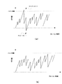
図4(a)に、特徴抽出のための符号化処理によりおける符号量の変化例を示す。図4(a)において、横軸は入力画像データのフレーム数(時間に対応する)を示し、縦軸は各フレーム毎の符号量を示す。また、VBVバッファ容量が破線で示されている。単位時間当たりの発生符号量は一定となっており、符号量の増加率(グラフの右上がり線分の傾き)は一定となる。また、入力画像データ中の情報量が多い(画像内容の変化が大きい)部分では符号量が増大するため、VBVバッファ16内の保持データ量がVBVバッファ16の容量を下回り、アンダーフローが生じうる。逆に入力画像データの情報量が少ない期間ではオーバーフローが生じうる。オーバーフロー又はアンダーフローが生じることをVBVバッファが破綻していると呼ぶ。VBVバッファ16の容量は符号化出力データの復号器のバッファサイズを想定しているので、VBVバッファ16が破綻するということは、そのときの符号化出力データは想定している復号器では正しく再生できないことを意味する。よって、オーバーフロー又はアンダーフローが生じた場合は適切な符号化が行えていないことを意味する。但し、特徴抽出のための符号化処理は入力画像データの特徴抽出のために量子化係数を固定して実行した、いわば試験的符号化処理であるのでオーバーフローやアンダーフローが生じることに問題はない。
【0034】
こうして、特徴抽出のための符号化処理により、入力画像データD0の特徴情報が得られると、次に符号量予測処理(ステップS2)を実施する。符号量予測処理の詳細を図3に示す。符号量予測処理は、特徴抽出のための符号化処理で得られた特徴情報を利用して、入力画像データの各フレームに対する最適な符号量割り当て、即ちフレーム毎の最適な量子化係数の設定を行う試験的な符号化処理である。なお、符号量予測処理も、図1に示すコントローラ20の制御下で、メモリ22に記憶されている特徴情報を利用して入力画像データを符号化することにより実行される。
【0035】
具体的には、図3に示すように、まずコントローラ20は入力画像データD0をシーン毎に分割する(ステップS11)。ステップS1で得られた特徴情報にはシーンチェンジ部分の情報が含まれているので、これを利用して入力画像データD0をシーン毎に分割されたフレーム画像の複数のまとまりに分割することができる。次に、コントローラ20は、シーン毎の平均符号量を計算する(ステップS12)。特徴情報にはフレーム毎の符号量が含まれているので、各シーンを構成する複数のフレームの符号量を合計し、フレーム数で除算することにより、フレーム毎の平均符号量を算出することができる。
【0036】
次に、各シーンについて、当該シーンの終了部分に対応するフレームについては重要度を低く設定する(ステップS13)。重要度は当該フレームが入力画像データ中において画像内容に大きな影響を与えるか否かにより決定され、具体的には当該フレームに割り当てる符号量、即ち量子化係数に影響を与える。通常、シーンチェンジの際には再生画像の観察者はチェンジ後の画像内容に強い印象を受ける傾向があり、シーンチェンジ直前のフレーム画像は多少画質を落としてもそれほど大きな悪影響はない。よって、シーン終了部のフレームに対しては重要度を低く設定する。
【0037】
次に、コントローラ20は、入力画像データを構成する各フレームに対して重み付けを行う。ここで、「重み」とは各フレーム毎に設定され、当該フレームに対してどれだけ多くの符号量を割り当てるべきであるかを示すパラメータである。よって、重みの値は、情報量の多いフレームや重要度の高いフレームに対しては大きな値に設定され、情報量の少ないフレームや重要度の低いフレームに対しては小さな値に設定される。重みの値は、例えば以下の計算式により設定することができる。
【0038】
重み = 1/[{(シーンの平均符号量)×重み係数1
+(符号化対象フレームの符号量−シーンの平均符号量)×重み係数2
+(符号化対象フレームの符号量−直前フレームの符号量)×重み係数3
+(符号化対象フレームの符号量/量子化係数)×重み係数4}
×シーン長による重み係数5]
ここで、重み係数1〜5は、予め決定される0〜1の範囲内の値である。
【0039】
次に、コントローラ20は、そのようにしてフレーム毎に設定された重み値をメモリ22などに記憶した後、その重み値に応じてフレーム毎の量子化係数を更新し、符号化シミュレーション(試験符号化)を実行する(ステップS15)。量子化係数の更新は、例えば特徴情報として得られ、メモリ22に記憶されている前回のフレーム毎の量子化係数の値に、フレーム毎の重み値を乗算することにより行うことができる。なお、符号化シミュレーションは、実際に決定された量子化係数を利用して符号化装置1により符号化を実行する処理となる。
【0040】
そして、符号化シミュレーション中にコントローラ20はVBVバッファ16からの制御信号CS1に基づいてVBVバッファ16が破綻したか否か、即ちオーバーフロー又はアンダーフローが発生したか否かを判定する(ステップS16)。
【0041】
VBVバッファ16に破綻が生じるということは、今回の符号化シミュレーションで使用したフレーム毎の量子化係数が不適当であることを意味するので、コントローラ20は重み値が最小であるフレームを探し、当該フレームの量子化係数を調整する(ステップS17)。ここで重み値が最小のフレームについて量子化係数を調整する理由は、量子化係数の調整により画像内容に大きな影響が出ることを防止するためである。また、量子化係数の調整としては、VBVバッファの破綻がオーバーフローであった場合には量子化係数を減少させて符号量を減少させ、VBVバッファの破綻がアンダーフローであった場合には量子化係数を増加させて符号量を増加させることになる。
【0042】
その後処理はステップS12へ戻り、再度各フレームに対して重み付けを行い、量子化係数を設定して符号化シミュレーションを繰り返す。そして、VBVバッファに破綻が生じない場合(ステップS16;No)、処理は図2に示すステップS3へ進む。VBVバッファに破綻が生じていない場合のフレーム毎の符号量の変化例を図4(b)に示す。図4(a)と比較するとわかるように、オーバーフローもアンダーフローも生じていないので、その際の符号化出力データは復号器による正しい復号が可能となる。
【0043】
こうして、符号量予測処理により、当該入力画像データについて、フレーム毎に適当な量子化係数が得られた(つまり、フレーム毎に適当な符号量の割り当てが完了した)ことになるので、符号化装置1はその量子化係数を使用して実際の符号化処理を行う(ステップS3)。なお、こうして得られた量子化係数を使用したにも拘わらず何らかの原因で実際の符号化処理中にVBVバッファが破綻することが予測された場合には、コントローラ20はVBVバッファ16からの制御信号CS1を利用して量子化係数の調整を行い、破綻を回避することができる。
【0044】
以上説明したように、本実施例では、まず入力画像データの特徴抽出のための符号化処理を実行して入力画像データの特徴情報を取得し、それを利用して符号量予測処理において重み値を調整しつつ符号化シミュレーションを行って最適な量子化係数を設定する。よって、入力画像データ全体の特徴を把握した上で最適な量子化係数の設定がなされるので、VBVバッファが破綻することを確実に防止することができるとともに、入力画像データの特徴に適合した符号化が可能となる。
【図面の簡単な説明】
【図1】本発明の実施例に係る符号化装置の概略構成を示すブロック図である。
【図2】本発明の実施例による符号化処理のフローチャートである。
【図3】図2に示す符号量予測処理のフローチャートである。
【図4】符号化処理中におけるVBVバッファ内データ量の推移を示す例である。
【符号の説明】
1 符号化装置
10 DCT
12 量子化部
14 符号化部
16 VBVバッファ
20 コントローラ
22 メモリ[0001]
TECHNICAL FIELD OF THE INVENTION
The present invention relates to compression coding of image information.
[0002]
[Prior art]
Generally, since moving image information has a huge data amount, a huge amount of storage capacity is required to store the moving image information in a storage medium or the like as it is. Therefore, in order to enable moving image data to be stored on an optical disk or other storage medium, an image compression encoding technique is known. MPEG is a representative example of a moving image compression encoding method.
[0003]
In a compression coding method such as MPEG, generally, motion prediction processing such as DCT (Discrete Cosine Transform) is performed on image data to be coded, and the obtained data is processed for each frequency component. Is quantized with a quantization coefficient (number of quantization bits) suitable for the encoding, and further encoded by a variable length encoding circuit. In general, quantization coefficients are assigned such that the low-frequency component is an important component constituting an image, so that the bit allocation is increased and the high-frequency component is reduced. When the quantization coefficient is set to be large, the code amount per one frame image is reduced, and when the quantization coefficient is set to be small, the code amount per one frame image is increased.
[0004]
Note that a method is known in which an image including a large amount of information is encoded by allocating a data amount corresponding to the amount of information included in the image to the image (for example, see Patent Document 1).
[0005]
In the conventional encoding process, a quantization coefficient of image data input thereafter is determined based on an average code amount of image data which has been subjected to the encoding process so far, and a code amount is allocated. . That is, at each time during the encoding process, the quantization of the encoding process to be executed after the current time (in the future) is performed based on the average code amount of the image data portion for which the encoding process has been completed before the current time (past). Coefficient setting (that is, code amount allocation) has been performed.
[0006]
[Patent Document 1]
Japanese Patent Application Laid-Open No. H11-136673
[Problems to be solved by the invention]
However, image data generally includes scenes (or frames) containing a large amount of information and scenes (or frames) not containing a large amount of information. For example, the amount of information is large when the image content changes greatly, such as when a scene changes, and the amount of information is not so large when images with similar contents continue. Therefore, as described above, when code amount allocation is performed based on the average code amount up to the current time during encoding, for example, when the image content changes abruptly at the time of a scene change, etc., an encoding result is obtained. The code amount rapidly increases and decreases, and overflow or underflow occurs in the VBV buffer that temporarily stores the encoded data. In order to prevent such overflow or underflow, rapid quantization is performed immediately before the overflow or underflow. Unnatural code amount adjustment such as changing coefficients may be performed. The problems to be solved by the present invention include, for example, those described above.
[0008]
The present invention has been made in view of the above points, and has as its object to assign an appropriate code amount throughout the entire video data based on the characteristics of the entire video data to be encoded.
[0009]
[Means for Solving the Problems]
According to a first aspect of the present invention, in the method for encoding image information, a feature extracting step of quantizing and encoding the entirety of the image information to be encoded to extract feature information; A code amount prediction step of performing quantization and encoding of the image information while changing a quantization coefficient to determine an appropriate quantization coefficient, and using the determined quantization coefficient to perform quantization of the image information. Encoding and encoding, and outputting the obtained result as encoded output data.
[0010]
The invention according to claim 4 is an image information encoding program executed on a computer, wherein the computer quantizes and encodes the entire image information to be encoded to extract characteristic information. A code amount predicting step of performing quantization and encoding of the image information while changing a quantization coefficient based on the characteristic information to determine an appropriate quantization coefficient; and And a coding step of performing quantization and coding of the image information using a coding coefficient and outputting the obtained result as coded output data.
[0011]
According to a fifth aspect of the present invention, in the image information encoding apparatus, a quantization unit that quantizes the image information with a predetermined quantization coefficient, and an encoding unit that encodes the quantized data generated by the quantization unit. Means, feature extraction means for quantizing and encoding the entire image information to extract feature information, and performing quantization and encoding of the image information while changing quantization coefficients based on the feature information. Code amount predicting means for determining an appropriate quantization coefficient, and quantizing and encoding the image information using the appropriate quantization coefficient, and outputting the obtained result as encoded output data. Encoding means.
[0012]
BEST MODE FOR CARRYING OUT THE INVENTION
A method for encoding image information according to a preferred embodiment of the present invention is a feature extraction step of extracting feature information by quantizing and encoding the entire image information to be encoded, based on the feature information, A code amount prediction step of performing quantization and encoding of the image information while changing a quantization coefficient to determine an appropriate quantization coefficient, and quantizing the image information by using the determined quantization coefficient. And encoding, and outputting the obtained result as encoded output data.
[0013]
In this method, when encoding image information, first, the entire image information to be encoded is quantized and encoded to extract feature information. This process has a character as a pre-process performed prior to the actual encoding process. When the characteristic information of the image information is obtained by the quantization and the encoding as the preprocessing, a code amount prediction step for determining an appropriate quantization coefficient is performed using the characteristic information. The feature information is information indicating an information amount or the like according to the content of the image information to be encoded, and the like. When encoding the image information by determining the quantization coefficient based on the feature information, , A suitable quantization coefficient can be obtained. The code amount prediction step can be repeatedly performed until an appropriate quantization coefficient is obtained. Then, when an appropriate quantization coefficient is obtained, an actual encoding step is performed. That is, the image information to be encoded is encoded using the appropriate quantization coefficient obtained in the code amount prediction step, and the result is output as encoded output data.
[0014]
According to this method, the feature of image information to be encoded is extracted in advance, and the process of determining an appropriate quantization coefficient based on the feature information is performed prior to the actual encoding process. Quantization and encoding suitable for the content and amount of image information to be converted are performed. Therefore, it is possible to prevent the VBV buffer from failing during the encoding process, or to prevent the VBV buffer from failing to rapidly adjust the quantization coefficient, and to encode image information with an appropriate code amount. Can be realized.
[0015]
In one aspect of the encoding method, the code amount prediction step includes: a coefficient setting step of setting a quantization coefficient for each frame based on the feature information; and A test encoding step of performing information quantization and encoding and storing encoding result data in a buffer; and a coefficient for changing a quantization coefficient for each frame when an overflow or underflow occurs in the buffer. And a changing step.
[0016]
In this aspect, based on the characteristic information, an appropriate quantization coefficient is set for each frame constituting the image information, and quantization and encoding are performed using the quantization coefficient to determine whether a failure occurs in the buffer. No, that is, whether overflow or underflow occurs. When a failure occurs in the buffer, the quantization coefficient for each frame is adjusted, and quantization and encoding are executed again to determine whether or not a failure occurs in the buffer. By repeating this, it is possible to obtain, for each frame, a quantization coefficient that matches the characteristic information of the image information and does not break the buffer.
[0017]
In one aspect of the above-described encoding method, the feature information includes a code amount for each frame obtained by encoding the image information and information for specifying a scene constituting the image information; Has a step of calculating a weight value for each frame, and the coefficient changing step includes, based on the calculated weight value and the quantization coefficient used in the previous test encoding of the frame, the changed quantum Coefficient can be set.
[0018]
In this aspect, as the feature information, the code amount for each frame and information for specifying a scene constituting the image information are acquired. A scene refers to a group of scenes or the like in image information. Usually, when a scene changes, the content of the image information changes relatively largely. Therefore, by using a code amount for each frame and information for specifying a scene, an appropriate weight value is set for each frame, and the quantization coefficient used in the previous test encoding is adjusted accordingly, so that a new weight is set. Set the quantization coefficient. In this way, the quantization coefficient assigned to each frame can be adjusted while matching the characteristics of the image information.
[0019]
Further, the image information encoding method may be realized by configuring an encoding program for executing the above-described feature extraction step, code amount prediction step, and encoding step, and executing the program on a computer. Can be.
[0020]
Also, an encoding apparatus for performing the above encoding method includes a quantization unit that quantizes the image information with a predetermined quantization coefficient, and an encoding unit that encodes the quantized data generated by the quantization unit. Means, feature extraction means for quantizing and encoding the entire image information to extract feature information, and performing quantization and encoding of the image information while changing quantization coefficients based on the feature information. Code amount predicting means for determining an appropriate quantization coefficient, and quantizing and encoding the image information using the appropriate quantization coefficient, and outputting the obtained result as encoded output data. Encoding means.
[0021]
【Example】
Hereinafter, preferred embodiments of the present invention will be described with reference to the drawings.
[0022]
FIG. 1 shows a schematic configuration of a video data encoding apparatus according to an embodiment of the present invention. The
[0023]
The
[0024]
The
[0025]
Output data D2 of the
[0026]
The output data D3 of the
[0027]
The
[0028]
The encoded output data D4 output from the
[0029]
Next, the encoding process according to the present invention will be described. FIG. 2 shows the flow of the encoding process according to the present invention. As shown, in the present invention, an encoding process for extracting features of input image data is performed before an actual encoding process is performed. Specifically, as shown in FIG. 2, first, encoding processing for feature extraction is performed (step S1), and feature information of input image data is obtained. Next, code amount prediction processing is performed using the feature information obtained in step S1 (step S2). This process is a process of predicting an optimal code amount for encoding the input image data and setting an optimal quantization coefficient. Then, when an optimal quantization coefficient is obtained, an actual encoding process is performed using the quantization coefficient (step S3). Thereby, encoded output data is obtained as a result of performing appropriate encoding processing.
[0030]
Next, each step will be described in detail. The encoding process for extracting the features is a process for examining the features of the input image data, and actually performs the encoding process using the
[0031]
Also, by comparing the code amount for each frame, a scene change portion in the input image data can be detected. The scene change portion is a portion where the content of the image data greatly changes, and a portion where a scene changes in a movie or other images corresponds to this. In the scene change portion, since the image content changes greatly, the code amount for each frame before and after the scene change also changes greatly. Therefore, the
[0032]
In this way, the
[0033]
FIG. 4A shows an example of a change in the code amount in the encoding process for feature extraction. In FIG. 4A, the horizontal axis indicates the number of frames (corresponding to time) of the input image data, and the vertical axis indicates the code amount for each frame. Further, the VBV buffer capacity is indicated by a broken line. The generated code amount per unit time is constant, and the rate of increase in the code amount (the slope of the line rising to the right in the graph) is constant. In addition, since the code amount increases in a portion of the input image data where the information amount is large (the change in the image content is large), the amount of data held in the
[0034]
When the feature information of the input image data D0 is obtained by the encoding process for feature extraction, the code amount prediction process (step S2) is performed. FIG. 3 shows details of the code amount prediction processing. The code amount prediction process uses the feature information obtained in the encoding process for feature extraction to assign an optimum code amount to each frame of the input image data, that is, to set an optimal quantization coefficient for each frame. This is a trial encoding process to be performed. Note that the code amount prediction process is also executed by encoding the input image data using the characteristic information stored in the
[0035]
Specifically, as shown in FIG. 3, first, the
[0036]
Next, for each scene, the degree of importance is set low for a frame corresponding to the end portion of the scene (step S13). The importance is determined by whether or not the frame has a significant effect on the image content in the input image data, and more specifically, has an influence on the code amount allocated to the frame, that is, the quantization coefficient. Usually, at the time of a scene change, the observer of the reproduced image tends to have a strong impression on the image content after the change, and even if the image quality of the frame image immediately before the scene change is slightly reduced, there is not so much adverse effect. Therefore, the importance is set low for the frame at the scene end.
[0037]
Next, the
[0038]
Weight = 1 / [{(average code amount of scene) ×
+ (Code amount of encoding target frame−average code amount of scene) ×
+ (Code amount of frame to be coded-code amount of previous frame) ×
+ (Code amount of encoding target frame / quantization coefficient) × weight coefficient 4}
× weight factor 5 by scene length]
Here, the
[0039]
Next, the
[0040]
Then, during the encoding simulation, the
[0041]
Since the failure of the
[0042]
After that, the process returns to step S12, weights each frame again, sets a quantization coefficient, and repeats the coding simulation. If no failure occurs in the VBV buffer (Step S16; No), the process proceeds to Step S3 shown in FIG. FIG. 4B shows an example of a change in the code amount for each frame when no failure occurs in the VBV buffer. As can be seen from comparison with FIG. 4A, since neither overflow nor underflow has occurred, the encoded output data at that time can be correctly decoded by the decoder.
[0043]
In this way, by the code amount prediction processing, an appropriate quantization coefficient has been obtained for each frame of the input image data (that is, an appropriate code amount has been allocated for each frame). 1 performs an actual encoding process using the quantized coefficient (step S3). If the VBV buffer is predicted to fail during the actual encoding process for some reason despite the use of the quantized coefficients thus obtained, the
[0044]
As described above, in the present embodiment, first, the encoding process for extracting the characteristics of the input image data is performed to acquire the characteristic information of the input image data, and the weight value is used in the code amount prediction process by using the obtained information. The optimal quantization coefficient is set by performing an encoding simulation while adjusting. Therefore, the optimum quantization coefficient is set after grasping the characteristics of the entire input image data, so that it is possible to reliably prevent the VBV buffer from breaking down, and to obtain a code suitable for the characteristics of the input image data. Is possible.
[Brief description of the drawings]
FIG. 1 is a block diagram illustrating a schematic configuration of an encoding device according to an embodiment of the present invention.
FIG. 2 is a flowchart of an encoding process according to an embodiment of the present invention.
FIG. 3 is a flowchart of a code amount prediction process shown in FIG. 2;
FIG. 4 is an example showing a transition of a data amount in a VBV buffer during an encoding process.
[Explanation of symbols]
1 Encoding
12
Claims (5)
前記特徴情報に基づいて、量子化係数を変更しつつ前記画像情報の量子化及び符号化を行って適当な量子化係数を決定する符号量予測工程と、
決定された量子化係数を利用して、前記画像情報の量子化及び符号化を行い、得られた結果を符号化出力データとして出力する符号化工程と、を有することを特徴とする画像情報の符号化方法。A feature extraction step of extracting the feature information by quantizing and encoding the entire image information to be encoded;
A code amount prediction step of determining an appropriate quantization coefficient by performing quantization and encoding of the image information while changing a quantization coefficient based on the feature information;
Using the determined quantization coefficient, performing quantization and encoding of the image information, and outputting an obtained result as encoded output data. Encoding method.
前記特徴情報に基づいてフレーム毎の量子化係数を設定する係数設定工程と、
設定された量子化係数を利用して、前記画像情報の量子化及び符号化を実行し、符号化結果データをバッファに格納する試験符号化工程と、
前記バッファにオーバーフロー又はアンダーフローが発生したときに、前記フレーム毎の量子化係数を変更する係数変更工程と、を有することを特徴とする請求項1に記載の画像情報の符号化方法。The code amount prediction step includes:
A coefficient setting step of setting a quantization coefficient for each frame based on the feature information,
A test encoding step of performing quantization and encoding of the image information using the set quantization coefficient, and storing encoding result data in a buffer.
2. The image information encoding method according to claim 1, further comprising: a coefficient changing step of changing a quantization coefficient for each frame when an overflow or an underflow occurs in the buffer.
前記試験符号化工程は前記フレーム毎の重み値を算出する工程を有し、
前記係数変更工程は、算出された重み値と当該フレームの前回の試験符号化で使用した量子化係数とに基づいて、変更後の量子化係数を設定することを特徴とする請求項1又は2に記載の符号化方法。The feature information includes a code amount for each frame obtained by encoding the image information, and information specifying a scene constituting the image information,
The test encoding step has a step of calculating a weight value for each frame,
The coefficient changing step sets a changed quantization coefficient based on a calculated weight value and a quantization coefficient used in a previous test encoding of the frame. Encoding method.
符号化の対象となる画像情報の全体を量子化及び符号化して特徴情報を抽出する特徴抽出工程と、
前記特徴情報に基づいて、量子化係数を変更しつつ前記画像情報の量子化及び符号化を行って適当な量子化係数を決定する符号量予測工程と、
前記適当な量子化係数を利用して、前記画像情報の量子化及び符号化を行い、得られた結果を符号化出力データとして出力する符号化工程と、を実行させることを特徴とする画像情報の符号化プログラム。By executing on a computer, the computer
A feature extraction step of extracting the feature information by quantizing and encoding the entire image information to be encoded;
A code amount prediction step of determining an appropriate quantization coefficient by performing quantization and encoding of the image information while changing a quantization coefficient based on the feature information;
Using the appropriate quantization coefficient, performing quantization and encoding of the image information, and outputting an obtained result as encoded output data. Encoding program.
前記量子化手段が生成した量子化データを符号化する符号化手段と、
前記画像情報の全体を量子化及び符号化して特徴情報を抽出する特徴抽出手段と、
前記特徴情報に基づいて、量子化係数を変更しつつ前記画像情報の量子化及び符号化を行って適当な量子化係数を決定する符号量予測手段と、
前記適当な量子化係数を利用して、前記画像情報の量子化及び符号化を行い、得られた結果を符号化出力データとして出力する符号化手段と、を有することを特徴とする画像情報の符号化装置。Quantization means for quantizing the image information with a predetermined quantization coefficient,
Encoding means for encoding the quantized data generated by the quantization means,
Feature extraction means for extracting feature information by quantizing and encoding the entire image information;
A code amount predicting unit that determines an appropriate quantization coefficient by performing quantization and encoding of the image information while changing a quantization coefficient based on the feature information,
Encoding means for performing quantization and encoding of the image information using the appropriate quantization coefficient, and outputting an obtained result as encoded output data. Encoding device.
Priority Applications (3)
| Application Number | Priority Date | Filing Date | Title |
|---|---|---|---|
| JP2002332137A JP2004166128A (en) | 2002-11-15 | 2002-11-15 | Method, device and program for coding image information |
| EP20030257076 EP1420365A3 (en) | 2002-11-15 | 2003-11-10 | Coding method, coding apparatus and coding program of image information |
| US10/713,032 US20040096113A1 (en) | 2002-11-15 | 2003-11-17 | Coding method, coding apparatus and coding program of image information |
Applications Claiming Priority (1)
| Application Number | Priority Date | Filing Date | Title |
|---|---|---|---|
| JP2002332137A JP2004166128A (en) | 2002-11-15 | 2002-11-15 | Method, device and program for coding image information |
Publications (1)
| Publication Number | Publication Date |
|---|---|
| JP2004166128A true JP2004166128A (en) | 2004-06-10 |
Family
ID=32171413
Family Applications (1)
| Application Number | Title | Priority Date | Filing Date |
|---|---|---|---|
| JP2002332137A Abandoned JP2004166128A (en) | 2002-11-15 | 2002-11-15 | Method, device and program for coding image information |
Country Status (3)
| Country | Link |
|---|---|
| US (1) | US20040096113A1 (en) |
| EP (1) | EP1420365A3 (en) |
| JP (1) | JP2004166128A (en) |
Cited By (8)
| Publication number | Priority date | Publication date | Assignee | Title |
|---|---|---|---|---|
| JP2008504750A (en) * | 2004-06-27 | 2008-02-14 | アップル インコーポレイテッド | Multi-pass video encoding |
| WO2008047714A1 (en) * | 2006-10-16 | 2008-04-24 | Panasonic Corporation | Code conversion method, transcoder, and integrated circuit thereof |
| JP2008236333A (en) * | 2007-03-20 | 2008-10-02 | Toshiba Corp | Video encoder and video encoding method |
| US8208536B2 (en) | 2005-04-28 | 2012-06-26 | Apple Inc. | Method and apparatus for encoding using single pass rate controller |
| US8355436B2 (en) | 2002-11-08 | 2013-01-15 | Apple Inc. | Method and apparatus for control of rate-distortion tradeoff by mode selection in video encoders |
| US8594190B2 (en) | 2004-06-27 | 2013-11-26 | Apple Inc. | Encoding with visual masking |
| US8811475B2 (en) | 2004-06-27 | 2014-08-19 | Apple Inc. | Multi-pass video encoding solution for buffer underflow |
| JP2022525911A (en) * | 2019-03-18 | 2022-05-20 | 芯原微電子(成都)有限公司 | Cooperative access method and system of external memory, coordinating access architecture |
Families Citing this family (5)
| Publication number | Priority date | Publication date | Assignee | Title |
|---|---|---|---|---|
| US20040141874A1 (en) * | 2003-01-15 | 2004-07-22 | Phillip Mullinax | System and apparatus for ozonating air and water for animal confinement houses |
| US7936938B2 (en) * | 2004-09-07 | 2011-05-03 | Canon Kabushiki Kaisha | Methods and devices for encoding a digital image signal and associated decoding methods and devices |
| JP4644097B2 (en) * | 2005-10-31 | 2011-03-02 | 富士通セミコンダクター株式会社 | A moving picture coding program, a program storage medium, and a coding apparatus. |
| JP4668767B2 (en) * | 2005-10-31 | 2011-04-13 | 富士通セミコンダクター株式会社 | Moving picture coding apparatus and moving picture coding program |
| CN103096081B (en) * | 2013-01-15 | 2016-04-20 | 深圳市中瀛鑫科技股份有限公司 | The processing method of conversion coefficient, Coding with Wavelets method and module and encoder |
Family Cites Families (5)
| Publication number | Priority date | Publication date | Assignee | Title |
|---|---|---|---|---|
| US5677969A (en) * | 1995-02-23 | 1997-10-14 | Motorola, Inc. | Method, rate controller, and system for preventing overflow and underflow of a decoder buffer in a video compression system |
| US6415057B1 (en) * | 1995-04-07 | 2002-07-02 | Sony Corporation | Method and apparatus for selective control of degree of picture compression |
| US5677689A (en) * | 1995-08-31 | 1997-10-14 | Yovanof; Gregory S. | Fixed rate JPEG compliant still image compression |
| FI107496B (en) * | 1997-07-18 | 2001-08-15 | Nokia Mobile Phones Ltd | Image Compressor Call |
| JP2002252770A (en) * | 2001-02-22 | 2002-09-06 | Matsushita Graphic Communication Systems Inc | Classification method for image information, image coding method, and image coder |
-
2002
- 2002-11-15 JP JP2002332137A patent/JP2004166128A/en not_active Abandoned
-
2003
- 2003-11-10 EP EP20030257076 patent/EP1420365A3/en not_active Withdrawn
- 2003-11-17 US US10/713,032 patent/US20040096113A1/en not_active Abandoned
Cited By (9)
| Publication number | Priority date | Publication date | Assignee | Title |
|---|---|---|---|---|
| US8355436B2 (en) | 2002-11-08 | 2013-01-15 | Apple Inc. | Method and apparatus for control of rate-distortion tradeoff by mode selection in video encoders |
| JP2008504750A (en) * | 2004-06-27 | 2008-02-14 | アップル インコーポレイテッド | Multi-pass video encoding |
| JP2011151838A (en) * | 2004-06-27 | 2011-08-04 | Apple Inc | Multi-pass video-encoding |
| US8594190B2 (en) | 2004-06-27 | 2013-11-26 | Apple Inc. | Encoding with visual masking |
| US8811475B2 (en) | 2004-06-27 | 2014-08-19 | Apple Inc. | Multi-pass video encoding solution for buffer underflow |
| US8208536B2 (en) | 2005-04-28 | 2012-06-26 | Apple Inc. | Method and apparatus for encoding using single pass rate controller |
| WO2008047714A1 (en) * | 2006-10-16 | 2008-04-24 | Panasonic Corporation | Code conversion method, transcoder, and integrated circuit thereof |
| JP2008236333A (en) * | 2007-03-20 | 2008-10-02 | Toshiba Corp | Video encoder and video encoding method |
| JP2022525911A (en) * | 2019-03-18 | 2022-05-20 | 芯原微電子(成都)有限公司 | Cooperative access method and system of external memory, coordinating access architecture |
Also Published As
| Publication number | Publication date |
|---|---|
| EP1420365A2 (en) | 2004-05-19 |
| EP1420365A3 (en) | 2004-06-23 |
| US20040096113A1 (en) | 2004-05-20 |
Similar Documents
| Publication | Publication Date | Title |
|---|---|---|
| KR101012600B1 (en) | Rate control with picture-based lookahead window | |
| US6968091B2 (en) | Insertion of noise for reduction in the number of bits for variable-length coding of (run, level) pairs | |
| CN1209929C (en) | Quantizing method and device for video compression | |
| US9774875B2 (en) | Lossless and near-lossless image compression | |
| CN1223197C (en) | Video bitrate control method and device for digital video recording | |
| US7177356B2 (en) | Spatially transcoding a video stream | |
| JPH1075451A (en) | Device and method for compressing video data | |
| US20120002724A1 (en) | Encoding device and method and multimedia apparatus including the encoding device | |
| JP2004166128A (en) | Method, device and program for coding image information | |
| JP2002223443A (en) | Transcoding method and transcoder | |
| JPH09154145A (en) | Video data compression method | |
| JP2004274236A (en) | Encoding apparatus, encoding method, program, and recording medium | |
| JP4179917B2 (en) | Video encoding apparatus and method | |
| JPH0722396B2 (en) | Image coding device | |
| JPH09149412A (en) | Video data compression method | |
| JP4586340B2 (en) | Encoding apparatus, encoding method, and program | |
| JP4168299B2 (en) | Image data conversion apparatus and image data conversion method | |
| JP4239734B2 (en) | Encoding apparatus, encoding method, and program | |
| JP4273385B2 (en) | Encoding apparatus, encoding method, program, and recording medium | |
| WO1999043157A1 (en) | System and method for non-causal encoding of video information for improved streaming thereof | |
| JP6985899B2 (en) | Image coding device and its control method and program | |
| JP4142927B2 (en) | Image compression method and image compression apparatus | |
| JP2007043495A (en) | Image processing device and image processing method | |
| JP3297472B2 (en) | Image compression coding device | |
| JP4273386B2 (en) | Encoding apparatus, encoding method, program, and recording medium |
Legal Events
| Date | Code | Title | Description |
|---|---|---|---|
| A621 | Written request for application examination |
Free format text: JAPANESE INTERMEDIATE CODE: A621 Effective date: 20051021 |
|
| A762 | Written abandonment of application |
Free format text: JAPANESE INTERMEDIATE CODE: A762 Effective date: 20070803 |