JP2004156282A - Flush toilet bowl - Google Patents
Flush toilet bowl Download PDFInfo
- Publication number
- JP2004156282A JP2004156282A JP2002322402A JP2002322402A JP2004156282A JP 2004156282 A JP2004156282 A JP 2004156282A JP 2002322402 A JP2002322402 A JP 2002322402A JP 2002322402 A JP2002322402 A JP 2002322402A JP 2004156282 A JP2004156282 A JP 2004156282A
- Authority
- JP
- Japan
- Prior art keywords
- jet
- bowl
- water
- jet nozzle
- flush toilet
- Prior art date
- Legal status (The legal status is an assumption and is not a legal conclusion. Google has not performed a legal analysis and makes no representation as to the accuracy of the status listed.)
- Pending
Links
Images


Abstract
Description
【0001】
【発明の属する技術分野】
本発明は、ボウル洗浄とゼット洗浄機能を備えた水洗便器に関する。
【0002】
【従来の技術】
従来の水洗便器のゼットノズル構造は、図7に示すようにゼット吐水口6がゼット吐水口取付面10と近接しており、かつゼットノズル7はゼット吐水方向に対して同軸の対称形状である構造となっていた(例えば、特許文献1参照)。また、図8に示すようにゼット吐水口取付面10から突出しかつ、ゼットノズル7はゼット吐水方向に対して同軸の対称形状である構造となっていた(例えば、特許文献2参照)。
【0003】
【特許文献1】
特開平04−143337号の全文明細書
【特許文献2】
実開平05−87079号の全文明細書
【0004】
【発明が解決しようとする課題】
しかしながら、図7および図8においては、ゼットノズル7がゼット吐水方向に対して同軸の対称形状であるために、ゼット吐水口6は、便器溜水11の最下部にならず、ゼット吐水口6より下の領域に死水領域9が発生し、その領域に残った汚水や浮遊汚物を、排出できない欠点があった。
【0005】
本発明は上記課題を解決すべくなされたもので、ゼット洗浄によって確実に汚水や浮遊汚物を排出できる水洗便器を提供することを目的とする。
【0006】
【課題を解決するための手段および作用・効果】
本発明の水洗便器はボウル洗浄を行うボウル吐水口とサイホンを起動させボウル内の水をブローで排出させるゼット吐水口とを備え、前記ゼット吐水口を構成するゼットノズルは陶器以外の材質で構成され、かつ前記ゼット吐水口位置が、便器溜水の最下部になるように前記ゼットノズルの一部にトラップ底面に倣って延長した延設部を設けたことを特徴とする。
ゼット吐水口の位置が便器溜水の最下部になるように前記ゼットノズルの一部にトラップ底面に倣って延長した延設部を設けたので、延設部によりゼット吐水口とトラップ底面との間で形成されるゼット吐水の死水領域がなくなり、サイホン直後に残った残水がすべてゼット吐水口に集まり、ゼット吐水を継続することにより、汚水や浮遊汚物を確実に排出することが可能になる。
【0007】
【発明の実施の形態】
以下、本発明の実施の形態を図面に基づいて説明する。
(実施例)
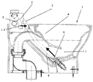
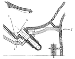
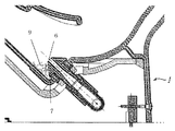
図1は本発明の一実施例のボウル洗浄とゼット洗浄を水道の圧力を利用して洗浄する水洗便器の説明図である。
【0008】
図1において、洗浄開始と同時に給水パイプ5と連結したボウル洗浄パイプ2に洗浄水を供給し、ボウル洗浄パイプ2を介してボウル吐水口12より吐水してボウル4の洗浄を始め所定時間が経過した後に、ボール洗浄をストップする。続いて給水パイプ5と連結したゼット洗浄パイプ3より洗浄水をゼットノズル6に供給しゼット吐水口7から吐水してゼット洗浄を開始する。ゼット洗浄が始まると、ゼットの水勢により、サイホンが開始し、汚水や汚物を排出し、便器溜水11の大部分が排出される。その後、ゼット流を継続することにより、サイホンにより排出できなかった汚水を排出する。ある時刻になった後に、ゼット流を停止し、最後に便器溜水11の再補給のために、ボウル吐水口12より給水を行なうものである。
【0009】
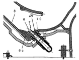
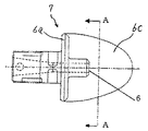
図2はゼットノズルを取り付けた状態を示す部分拡大図である。図3はゼットノズルの上面図、図4は図3のA−A断面図、図5はゼットノズルの側面図である。
ゼットノズル7は、陶器製の水洗便器1のゼットノズル取付面10に固定するためのフランジ部6a、ゼット吐水口6の中心軸6bより下側でゼット吐水口6の前側に斜め下方に延設したスコップ状の延設部6cを備えている。ゼットノズル7は図4に示すように、ゼット吐水口6が便器溜水11の最下部になるように、ゼット吐水口6に向かって延設部6cが折れた形状をしている。図2に示すように、ゼットノズル7をゼットノズル取付面10に固定した状態で、トラップ底面8に対して延設部6cが倣って配置され、ゼット吐水口6が便器溜水11の最下点になるように構成されている。
【0010】
ゼットノズル7を上記のような形状とすることにより、ゼット吐水口6より下の死水領域がなくなる。そのためサイホンの直後に残った汚水がゼット吐水口6に向かって流れ、ゼット吐水口6からの吐水を継続することにより、汚水や浮遊汚物を確実に排出することが可能になる。
【0011】
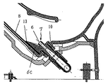
また、陶器製の水洗便器1の寸法のばらつきが大きい場合には、ゼットノズル7の形状がトラップ底面8の形状に沿わない場合がある。その場合は、図6に示すように、ゼットノズル7とトラップ底面8の間にあらかじめ隙間を設け、その隙間にゴムパッキン13を介設して前記隙間を埋めるようにすることにより、ゼットノズル7とトラップ底面8の間の寸法ばらつきを抑えることが可能である。
【図面の簡単な説明】
【図1】本発明の一実施例の水洗便器の説明図。
【図2】ゼットノズルを取り付けた状態を示す部分拡大図。
【図3】ゼットノズルの上面図。
【図4】図3のA−A断面図。
【図5】ゼットノズルの側面図。
【図6】ゼットノズルとトラップ底面の間をパッキンでシールした場合のゼットノズル付近の拡大図。
【図7】従来のゼット吐水口フランジの説明図。
【図8】従来のゼット吐水口フランジの説明図。
【符号の説明】
1…水洗便器
2…ボウル洗浄パイプ
3…ゼット洗浄パイプ
4…ボウル
5…給水パイプ
6…ゼット吐水口
6a…フランジ
6b…中心軸
6c…延設部
7…ゼットノズル
8…トラップ底面
9…死水領域
10…ゼットノズル取付面
11…便器溜水
12…ボウル吐水口
13…ゴムパッキン[0001]
TECHNICAL FIELD OF THE INVENTION
TECHNICAL FIELD The present invention relates to a flush toilet having a bowl cleaning function and a zet cleaning function.
[0002]
[Prior art]
The jet nozzle structure of the conventional flush toilet has a
[0003]
[Patent Document 1]
Japanese Patent Application Laid-Open No. 04-143337 [Patent Document 2]
Full text specification of Japanese Utility Model Laid-Open No. 05-87079
[Problems to be solved by the invention]
However, in FIG. 7 and FIG. 8, since the
[0005]
SUMMARY OF THE INVENTION The present invention has been made to solve the above problems, and has as its object to provide a flush toilet that can reliably discharge wastewater and suspended waste by jet cleaning.
[0006]
[Means for Solving the Problems and Functions / Effects]
The flush toilet of the present invention includes a bowl spout for performing bowl washing and a jet spout for activating a siphon and discharging water in the bowl by blowing, and a jet nozzle constituting the jet spout is made of a material other than ceramics. In addition, an extended portion extending along the bottom surface of the trap is provided in a part of the jet nozzle so that the jet outlet of the jet is located at the lowermost part of the toilet water.
An extended portion extending along the bottom surface of the trap is provided in a part of the jet nozzle so that the position of the jet water outlet is located at the bottom of the toilet water. There is no dead water area formed between the jet discharges, and the remaining water immediately after the siphon collects at the jet discharge port, and by continuing the jet discharge, it is possible to reliably discharge sewage and suspended waste. .
[0007]
BEST MODE FOR CARRYING OUT THE INVENTION
Hereinafter, embodiments of the present invention will be described with reference to the drawings.
(Example)
FIG. 1 is an explanatory view of a flush toilet for cleaning a bowl and a jet according to an embodiment of the present invention using the pressure of tap water.
[0008]
In FIG. 1, washing water is supplied to a
[0009]
FIG. 2 is a partially enlarged view showing a state where the jet nozzle is attached. FIG. 3 is a top view of the jet nozzle, FIG. 4 is a sectional view taken along line AA of FIG. 3, and FIG. 5 is a side view of the jet nozzle.
The
[0010]
By making the
[0011]
In addition, when the dimensional variation of the
[Brief description of the drawings]
FIG. 1 is an explanatory view of a flush toilet according to one embodiment of the present invention.
FIG. 2 is a partially enlarged view showing a state in which a jet nozzle is attached.
FIG. 3 is a top view of a Zet nozzle.
FIG. 4 is a sectional view taken along line AA of FIG. 3;
FIG. 5 is a side view of a Zet nozzle.
FIG. 6 is an enlarged view of the vicinity of the jet nozzle when the space between the jet nozzle and the trap bottom is sealed with packing.
FIG. 7 is an explanatory view of a conventional jet water outlet flange.
FIG. 8 is an explanatory view of a conventional jet water outlet flange.
[Explanation of symbols]
DESCRIPTION OF
Claims (1)
前記ゼット吐水口を構成するゼットノズルは陶器以外の材質で構成され、かつ前記ゼット吐水口位置が便器溜水の最下部になるように前記ゼットノズルの一部にトラップ底面に倣って延長した延設部を設けたことを特徴とする水洗便器。In a flush toilet equipped with a bowl spout for performing bowl washing, and a jet spout for activating the siphon and discharging water in the bowl by blowing,
The jet nozzle that constitutes the jet water outlet is made of a material other than ceramics, and extends along a trap bottom surface in a part of the jet nozzle so that the jet water outlet position is located at the bottom of the toilet water. A flush toilet characterized by having an installation part.
Priority Applications (1)
| Application Number | Priority Date | Filing Date | Title |
|---|---|---|---|
| JP2002322402A JP2004156282A (en) | 2002-11-06 | 2002-11-06 | Flush toilet bowl |
Applications Claiming Priority (1)
| Application Number | Priority Date | Filing Date | Title |
|---|---|---|---|
| JP2002322402A JP2004156282A (en) | 2002-11-06 | 2002-11-06 | Flush toilet bowl |
Publications (2)
| Publication Number | Publication Date |
|---|---|
| JP2004156282A true JP2004156282A (en) | 2004-06-03 |
| JP2004156282A5 JP2004156282A5 (en) | 2005-10-20 |
Family
ID=32802598
Family Applications (1)
| Application Number | Title | Priority Date | Filing Date |
|---|---|---|---|
| JP2002322402A Pending JP2004156282A (en) | 2002-11-06 | 2002-11-06 | Flush toilet bowl |
Country Status (1)
| Country | Link |
|---|---|
| JP (1) | JP2004156282A (en) |
Cited By (2)
| Publication number | Priority date | Publication date | Assignee | Title |
|---|---|---|---|---|
| JP2010106447A (en) * | 2008-10-28 | 2010-05-13 | Inax Corp | Toilet bowl flushing nozzle |
| CN111622320A (en) * | 2019-02-28 | 2020-09-04 | 科勒公司 | Fluid connector for toilet |
-
2002
- 2002-11-06 JP JP2002322402A patent/JP2004156282A/en active Pending
Cited By (4)
| Publication number | Priority date | Publication date | Assignee | Title |
|---|---|---|---|---|
| JP2010106447A (en) * | 2008-10-28 | 2010-05-13 | Inax Corp | Toilet bowl flushing nozzle |
| CN111622320A (en) * | 2019-02-28 | 2020-09-04 | 科勒公司 | Fluid connector for toilet |
| US11299877B2 (en) | 2019-02-28 | 2022-04-12 | Kohler Co. | Fluid connector for toilet |
| US11639599B2 (en) | 2019-02-28 | 2023-05-02 | Kohler Co. | Fluid connector for toilet |
Similar Documents
| Publication | Publication Date | Title |
|---|---|---|
| JP5180295B2 (en) | Western-style toilet with an overflow prevention auxiliary tank | |
| EP1847656B1 (en) | Flush toilet stool | |
| JP5804242B2 (en) | Flush toilet | |
| WO1998016696A1 (en) | Flush toilet | |
| JP2007063980A (en) | Toilet washing device and washing method | |
| JP2011058300A (en) | Wash-out type toilet bowl | |
| JP2012172403A (en) | Water closet | |
| JP2007046307A (en) | Toilet bowl flushing apparatus | |
| JP5299832B2 (en) | Flush toilet | |
| JP2018105048A (en) | Flush toilet bowl | |
| CA2357869A1 (en) | Toilet tank with sediment removal assembly | |
| JP5352948B2 (en) | Flush toilet | |
| JP2004156282A (en) | Flush toilet bowl | |
| WO2012026331A1 (en) | Flush toilet | |
| JP2007314957A (en) | Western-style toilet bowl equipment | |
| JP2007314974A (en) | Western style toilet bowl device | |
| JP2011208416A (en) | Flush toilet bowl | |
| JP2002309655A (en) | Toilet stool equipped with inspection port | |
| JP2014058863A (en) | Flush toilet bowl | |
| JP2798193B2 (en) | Flush toilet | |
| US20060230525A1 (en) | Method and apparatus to reduce toilet splash using water current and turbulence | |
| JP2011074689A (en) | Wash-off flush toilet | |
| JP2011202400A (en) | Flushing type toilet bowl | |
| JP7029629B2 (en) | Tank device | |
| JP2000008464A (en) | Flush stool |
Legal Events
| Date | Code | Title | Description |
|---|---|---|---|
| A521 | Written amendment |
Free format text: JAPANESE INTERMEDIATE CODE: A523 Effective date: 20050622 |
|
| A621 | Written request for application examination |
Free format text: JAPANESE INTERMEDIATE CODE: A621 Effective date: 20050622 |
|
| A977 | Report on retrieval |
Free format text: JAPANESE INTERMEDIATE CODE: A971007 Effective date: 20070216 |
|
| A131 | Notification of reasons for refusal |
Effective date: 20070227 Free format text: JAPANESE INTERMEDIATE CODE: A131 |
|
| RD02 | Notification of acceptance of power of attorney |
Effective date: 20070416 Free format text: JAPANESE INTERMEDIATE CODE: A7422 |
|
| A521 | Written amendment |
Free format text: JAPANESE INTERMEDIATE CODE: A523 Effective date: 20070425 |
|
| A131 | Notification of reasons for refusal |
Free format text: JAPANESE INTERMEDIATE CODE: A131 Effective date: 20071120 |
|
| A02 | Decision of refusal |
Effective date: 20080408 Free format text: JAPANESE INTERMEDIATE CODE: A02 |