JP2004156178A - Working glove made of rubber and method for producing the same - Google Patents
Working glove made of rubber and method for producing the same Download PDFInfo
- Publication number
- JP2004156178A JP2004156178A JP2002323844A JP2002323844A JP2004156178A JP 2004156178 A JP2004156178 A JP 2004156178A JP 2002323844 A JP2002323844 A JP 2002323844A JP 2002323844 A JP2002323844 A JP 2002323844A JP 2004156178 A JP2004156178 A JP 2004156178A
- Authority
- JP
- Japan
- Prior art keywords
- glove
- rubber
- slip
- natural rubber
- mold
- Prior art date
- Legal status (The legal status is an assumption and is not a legal conclusion. Google has not performed a legal analysis and makes no representation as to the accuracy of the status listed.)
- Pending
Links
Images


Abstract
Description
【0001】
【発明の属する技術分野】
本発明は作業用ゴム製手袋に関し、詳しくは、表面に滑り止め機能を備え、例えば台所等での水仕事において食器等を滑り落ちることのないよう掴むことができる使用感に優れたゴム製手袋とその製造方法に関する。
【0002】
【従来の技術】
従来、塩化ビニルや天然ゴムからなる作業用手袋として、サポート型のものとノンサポート型のものが知られている。
サポート型の手袋は、例えば特許文献1に記載されるように、繊維製の手袋基材を被せた手袋型を、塩化ビニルペーストや天然ゴムラテックス溶液中に浸漬してその表面に塩化ビニルや天然ゴム製の手袋本体を製膜し、そのまま手袋型から外して得られるものである。
【0003】
一方、ノンサポート型の手袋は、例えば特許文献2に記載されるように、手袋型を塩化ビニルペースト中に浸漬して、手袋型表面に塩化ビニルの手袋本体を製膜し、その外面側に短毛類層を形成した後、その手袋本体を反転させて手袋型から離型し、裏面に短毛類層を有する製品とするものである。
【0004】
【特許文献1】
特開昭59−163404号公報
【特許文献2】
特開平7−26404号公報
【0005】
【発明が解決しようとする課題】
ところで、この種作業用手袋の表面に滑り止め機能を持たせる場合、サポート型手袋においては、手袋型表面に製膜された手袋本体の外面側がそのまま製品表面になるので、その手袋本体の外面側に各種の滑り止め加工を施すことができる。
ところが、ノンサポート型手袋においては、手袋型表面に製膜された手袋本体の内面側が製品表面になるので、その内面側に滑り止め機能を持たせるために、手袋型の表面にエンボス加工用の凹凸の模様をつけ、この凹凸を、製膜される手袋本体の内面側に転写することで、離型後の手袋本体表面に滑り止め機能が付与されるようになっていた。
【0006】
しかしながら、上記した方法でゴム製手袋の表面に転写された凹凸では滑り止め効果が充分とは言えず、例えば台所等での水仕事に用いた場合、掴んだ食器等を滑り落とす虞れがあった。
このような問題点を解決するために、前記特許文献2には、微粉体等を含有する滑り止め層を手袋型表面に形成した後、手袋本体を形成する方法が記載されているが、このような方法を天然ゴム製の手袋に応用した場合、微粉体等の付着が完全でなく、製造途中或いは製造後に微粉体等が脱落し易いという問題があった。
【0007】
本発明はこのような従来事情に鑑みてなされたもので、その目的とする処は、ゴム製手袋本体の表面に充分な滑り止め効果を持たせたノンサポート型の作業用ゴム製手袋とその製造方法を提供することにある。
【0008】
【課題を解決するための手段】
前述した従来事情に鑑み、本願発明者等は鋭意研究を重ねた結果、ノンサポート型の作業用ゴム製手袋の製造過程において、天然ゴムアクリル共重合ポリマーと滑り止め粒子を混合させた混合層が、天然ゴムラテックスからなる手袋本体の表面に多数の滑り止め粒子を固着させるのに極めて有用であることを見い出し、本発明を完成するに至った。
【0009】
すなわち、本発明に係るノンサポート型の作業用ゴム製手袋は、天然ゴムラテックスからなる手袋本体の表面に、手袋型表面の凹凸模様を転写してなるエンボス加工と、前記手袋本体表面に一体的に固着された多数の滑り止め粒子とからなる滑り止め部が形成されていることを特徴とする。
【0010】
このような構成によれば、エンボス加工による滑り止め機能と、多数の滑り止め粒子による滑り止め機能とを兼ね備え、これらの相乗効果により、素手で物を掴む感覚に近似した滑り止め効果を発揮することができる。
【0011】
前記滑り止め粒子は、天然ゴムアクリル共重合ポリマー層により、前記手袋本体の表面に一体的に固着されていることが好ましい。
このような構成とした場合、天然ゴムアクリル共重合ポリマー層が、天然ゴムラテックスからなる手袋本体の表面と一体化し、多数の滑り止め粒子を、天然ゴムラテックス製手袋本体の表面にしっかりと固着させることができる。
【0012】
ノンサポート型ゴム製手袋の製造過程において、前記天然ゴムアクリル共重合ポリマー層は、前記手袋本体の製膜前に手袋型の表面に形成される。
すなわち、天然ゴムアクリル共重合ポリマー層を手袋型表面に形成した後、その表面に天然ゴムラテックスからなる手袋本体層を製膜すると、天然ゴムアクリル共重合ポリマーが手袋本体の内面側(製品における手袋本体表面)と混合して、手袋本体の内面側をゲル化(凝固)させ、これにより天然ゴムアクリル共重合ポリマー層に含有されている多数の滑り止め粒子が、手袋本体の内面側に強固に固着されるようになる。
また、天然ゴムアクリル共重合ポリマー層は、手袋本体に所定の厚みを持たせることにも寄与する。
【0013】
前記滑り止め粒子としては、アクリル等の合成樹脂製の粒子やガラス粒子等を用いることもできるが、手袋製造途中や製造後の脱落を防止すると共に、前記した顕著な滑り止め効果を得るためには、ゴム粒子を用いることが好ましい。
【0014】
また、本発明に係るゴム製手袋は前述したように、エンボス加工による滑り止め機能と、多数の滑り止め粒子による滑り止め機能との相乗効果により、素手で物を掴む感覚に近似した顕著な滑り止め効果が得られるものであるが、このような滑り止め効果を得るには、前記エンボス加工の形成ピッチが0.5〜1mm、滑り止め粒子の粒径が20〜50メッシュであることが好ましい。
【0015】
また、本発明に係るゴム製手袋は、表面にエンボス加工用の凹凸模様が形成された手袋型を、凝固剤溶液中に浸漬した後、多数の滑り止め粒子を含有する天然ゴムアクリル共重合ポリマー溶液中に浸漬して前記手袋型の表面に滑り止め粒子を付着させ、次いでその手袋型を凝固剤溶液中に再度浸漬して、前記多数の滑り止め粒子を含有した天然ゴムアクリル共重合ポリマーと凝固剤の混合層を形成し、さらにその手袋型を天然ゴムラテックス溶液中に浸漬して、エンボス加工と多数の滑り止め粒子からなる滑り止め部が内面に形成された手袋本体を製膜し、該手袋本体を反転させて手袋型から離型することを特徴とする方法により容易に製造することができる。
【0016】
また本発明に係るゴム製手袋は、前記方法において、手袋本体を製膜した後、前記手袋型を、短毛類を含有した天然ゴムラテックス溶液中に浸漬して、該手袋本体の外面側に短毛類層を形成し、しかる後、その手袋本体を反転させて手袋型から離型する工程を含むことにより、裏面に短毛類層を備えたゴム製手袋として容易に製造することができる。
【0017】
【発明の実施の形態】
以下、本発明に係る作業用ゴム製手袋(以下、単に「手袋」と称する)の実施形態の一例を図面を参照しながら説明する。
【0018】
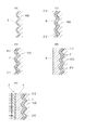
図1には本例の手袋Aを示し、この手袋Aは、手袋本体1の少なくとも掌部分の表面に滑り止め部2が形成されていると共に、手袋本体1の裏面全域にわたって短毛類層3が形成されているノンサポート型のゴム製手袋である。
【0019】
手袋本体1は、後述する天然ゴムラテックス溶液により、厚さ0.2〜0.5mm程度に製膜されている。
【0020】
滑り止め部2は、図2,図3に拡大断面で示すように、エンボス加工2−1と多数の滑り止め粒子2−2から形成されている。
【0021】
エンボス加工2−1は、手袋本体1を成形する陶磁器製又は金属製の手袋型表面の凹凸模様を転写してなる多数の凹凸からなり、隣り合わせる凹部と凸部の形成ピッチ(エンボス加工の形成ピッチ)は0.5〜1mm、凹部の深さは0.1〜0.5mmであることが好ましい。
【0022】
滑り止め粒子2−2は、手袋本体1の製膜前に手袋型の表面に形成される、天然ゴムアクリル共重合ポリマー層4により、手袋本体1の表面に一体的に固着されている。滑り止め粒子2−2としては、粒径が20〜50メッシュのゴム粒子が好ましく用いられる。
【0023】
短毛類層3は、手袋本体1の裏面に多数のパイルを付着させてなるもので、後述するパイル含有天然ゴムラテックス溶液により、厚さ0.1〜0.2mm程度に形成されている。
なお、短毛類層3は、手袋本体1の裏面に所望の滑り性を持たせて手袋Aの脱着を容易にするためのもので、例えば、手袋本体1の製膜後にその裏面を塩素化処理することでも同様の機能を得ることができる。
【0024】
天然ゴムアクリル共重合ポリマー層4は、後述する天然ゴムアクリル共重合ポリマー溶液により、厚さ0.1mm程度に形成されるもので、手袋本体1を所定の厚みに調整することにも寄与している。
【0025】
このような構成になる本例の手袋Aは、天然ゴムアクリル共重合ポリマー層4により、多数の滑り止め粒子2−2が手袋本体1の表面に強固に保持され、この天然ゴムアクリル共重合ポリマー層4が手袋本体1の製膜表面と一体化して、エンボス加工2−1が施された手袋Aの表面に多数の滑り止め粒子2−2がしっかりと固着される。
よって、手袋Aの表面には、エンボス加工2−1と多数の滑り止め粒子2−2とからなる滑り止め部2が形成され、該エンボス加工2−1と多数の滑り止め粒子2−2による滑り止め機能の相乗効果により、素手で物を掴む場合に近似した滑り止め効果を得ることができる。
【0026】
以下、本例の手袋Aの製造方法について、図4〜図6を参照しながら説明する。
・工程(1)〜(2)
まず、前記エンボス加工2−1用の凹凸模様101が手の甲部分と掌部分の表面に形成された手袋型100を、下記配合の凝固剤溶液110中に浸漬し、引き上げた後、温度90℃で5分間乾燥して、手袋型100の表面に凝固剤層5を形成した(図5,図6(a))。
【0027】
〔凝固剤溶液の配合〕
硝酸カルシウム:20重量部
ドデシルベンゼンスルホン酸ナトリウム:0.5重量部
メタノール又は水:80重量部
【0028】
・工程(3)〜(4)
次に、この手袋型100を、前記滑り止め粒子としてのゴム粒子2−2を多数含有する下記配合の天然ゴムアクリル共重合ポリマー溶液中に浸漬し、引き上げた後、温度90℃で5分間乾燥して、手袋型100の表面に、天然ゴムアクリル共重合ポリマーと凝固剤の混合層6を形成すると共にゴム粒子2−2を多数付着させた(図6(b))。
【0029】
〔滑り止め粒子含有天然ゴムアクリル共重合ポリマー溶液の配合〕
天然ゴムアクリル共重合ポリマー(ドライ):100重量部
ゴム粒子(粒径30メッシュ):10重量部
ドデシルベンゼンスルホン酸ナトリウム:0.5重量部
水:400重量部
【0030】
・工程(5)〜(6)
次いで、この手袋型100を前記した凝固剤溶液110中に再度浸漬し、引き上げた後、温度90℃で5分間乾燥して、前記混合層6に凝固剤が混合した混合層7を形成し、該混合層7により、前記ゴム粒子2−2を固着させた(図6(c))。
【0031】
・工程(7)〜(8)
さらにその手袋型100を、下記配合の天然ゴムラテックス溶液中に浸漬し、引き上げた後、温度90℃で5分間乾燥して、前記混合層7の上に、手袋本体1になる天然ゴムラテックス層8を形成した。
この時、天然ゴムラテックス層8の内面側(手袋型100側)は、前記混合層7と混合してゲル化(凝固)し、前記多数のゴム粒子2−2が、天然ゴムラテックス層8の内面側に強固に固着される状態になった(図6(d))。
【0032】
〔天然ゴムラテックス溶液の配合〕
天然ゴムラテックス(ドライ):100重量部
硫 黄:1重量部
亜 鉛 華:1重量部
シ゛フ゛チルシ゛チオカルハ゛ミン酸亜鉛(カーバメート促進剤):0.8重量部
2,6−シ゛−第三フ゛チル4−メチルフェノール(フェノール系老化防止剤):1重量部
ドデシルベンゼンスルホン酸ナトリウム:0.5重量部
水:100重量部
【0033】
・工程(9)〜(10)
さらにその手袋型100を、短毛類(パイル)を含有した下記配合の天然ゴムラテックス溶液中に浸漬し、引き上げた後、温度90℃で30分間乾燥して、多数のゴム粒子2−2を含有した天然ゴムアクリル共重合ポリマー層4を内面側に有し、多数の短毛類(パイル)を含有した短毛類層3を外面側に有する手袋本体1を製膜した(図6(e))。
【0034】
〔パイル含有天然ゴムラテックス溶液の配合〕
天然ゴムラテックス(ドライ):100重量部
硫 黄:1重量部
亜 鉛 華:1重量部
シ゛フ゛チルシ゛チオカルハ゛ミン酸亜鉛(カーバメート促進剤):0.8重量部
2,6−シ゛−第三フ゛チル4−メチルフェノール(フェノール系老化防止剤):1重量部
ドデシルベンゼンスルホン酸ナトリウム:0.5重量部
パイル:5重量部
水:300重量部
【0035】
・工程(11)〜(13)
次に、この手袋型100から手袋本体1を反転させながら離型し、洗浄により凝固剤と不純物を抽出した後、温度90℃で60分間加硫して、エンボス加工2−1と多数の滑り止め粒子2−2からなる滑り止め部2が手袋本体1表面に形成され、短毛類層3が手袋本体1裏面全域に形成されたノンサポート型作業用ゴム製手袋Aを得た。
【0036】
以上、本発明に係るノンサポート型作業用ゴム製手袋の実施形態の一例について説明したが、本発明は本例に限定されるものではなく、特許請求範囲の各請求項に記載される技術的思想の範疇において種々の変更が可能であることは言うまでもない。
【0037】
【発明の効果】
本発明に係るゴム製手袋は以上説明したように、エンボス加工される手袋本体の表面に滑り止め粒子を一体的に固着してなるので、従来のノンサポート型ゴム製手袋では得られなかった顕著な滑り止め効果、すなわち、素手で物を掴む場合に近似した充分な滑り止め効果を備え、例えば台所での水仕事において食器等を滑り落ちることのないよう掴むことができる、使用感に優れた新規なノンサポート型作業用ゴム製手袋を得ることができた。
【0038】
また、滑り止め粒子を天然ゴムアクリル共重合ポリマー層により手袋表面に強固に固着させることで、製造途中や使用中における滑り止め粒子の脱落を防止して、前記効果を確実に得ることがでる信頼性の高いノンサポート型作業用ゴム製手袋を提供することができた。
【0039】
また本発明に係るゴム製手袋の製造方法によれば、前記効果を有するノンサポート型のゴム製手袋を容易に製造することができた。
【図面の簡単な説明】
【図1】本発明に係る作業用ゴム製手袋の一例を示す正面図で、一部切欠して表す。
【図2】図1の(X)−(X)線に沿う拡大断面図。
【図3】図2の要部拡大図。
【図4】本発明に係る作業用ゴム製手袋の製造工程を示す説明図。
【図5】凝固剤溶液への浸漬工程を示す簡略図。
【図6】各工程における製膜状態を示す手袋型表面の拡大断面図。
【符号の説明】
A:ゴム製手袋
1:手袋本体
2:滑り止め部
2−1:エンボス加工
2−2:滑り止め粒子
3:短毛類層
4:天然ゴムアクリル共重合ポリマー層
5:凝固剤層
6:天然ゴムアクリル共重合ポリマーと凝固剤の混合層
7:混合層6と凝固剤の混合層
8:天然ゴムラテックス層(手袋本体)
100:手袋型
101:凹凸模様[0001]
TECHNICAL FIELD OF THE INVENTION
The present invention relates to a working rubber glove, and more particularly, to a rubber glove excellent in usability, which has a non-slip function on its surface and can grip tableware and the like without slipping off in water work in a kitchen or the like. It relates to the manufacturing method.
[0002]
[Prior art]
2. Description of the Related Art Conventionally, there are known support gloves and non-support gloves as work gloves made of vinyl chloride or natural rubber.
As described in
[0003]
On the other hand, as described in
[0004]
[Patent Document 1]
JP-A-59-163404 [Patent Document 2]
JP-A-7-26404
[Problems to be solved by the invention]
By the way, when the surface of this type of work glove has a non-slip function, in the case of a support type glove, since the outer surface side of the glove body formed on the glove type surface becomes the product surface as it is, the outer surface side of the glove body Can be subjected to various types of non-slip processing.
However, in the case of non-support type gloves, the inner surface of the glove body formed on the glove type surface is the product surface. By providing an uneven pattern and transferring the unevenness to the inner surface of the glove body to be formed into a film, the glove body surface after release has a non-slip function.
[0006]
However, the unevenness transferred to the surface of the rubber glove by the above-described method does not provide a sufficient anti-slip effect. For example, when used for water work in a kitchen or the like, there is a possibility that the caught tableware or the like may slip off. Was.
In order to solve such a problem,
[0007]
The present invention has been made in view of such a conventional situation, and an object thereof is to provide a non-support type working rubber glove having a sufficient anti-slip effect on the surface of a rubber glove body, and a glove for the same. It is to provide a manufacturing method.
[0008]
[Means for Solving the Problems]
In view of the above-mentioned conventional circumstances, the inventors of the present application have conducted intensive studies, and as a result, in the process of producing a non-support type working rubber glove, a mixed layer in which a natural rubber acrylic copolymer and non-slip particles were mixed was formed. The present invention has been found to be extremely useful for fixing a large number of non-slip particles on the surface of a glove body made of natural rubber latex, and has completed the present invention.
[0009]
That is, the non-support type working rubber glove according to the present invention is embossed by transferring an uneven pattern of the glove-type surface to the surface of the glove body made of natural rubber latex, and integrated with the glove body surface. A non-slip portion comprising a large number of non-slip particles fixed to the surface is formed.
[0010]
According to such a configuration, a non-slip function by embossing and a non-slip function by a large number of non-slip particles are provided, and by these synergistic effects, a non-slip effect similar to a feeling of grasping an object with bare hands is exerted. be able to.
[0011]
It is preferable that the non-slip particles are integrally fixed to the surface of the glove body by a natural rubber acrylic copolymer layer.
In the case of such a configuration, the natural rubber acrylic copolymer layer is integrated with the surface of the glove body made of natural rubber latex, and many anti-slip particles are firmly adhered to the surface of the natural rubber latex glove body. be able to.
[0012]
In the manufacturing process of the non-support type rubber glove, the natural rubber acrylic copolymer layer is formed on the surface of the glove mold before forming the glove body.
That is, after a natural rubber acrylic copolymer layer is formed on a glove-shaped surface, a glove body layer made of natural rubber latex is formed on the surface. When the natural rubber acrylic copolymer is formed on the inner surface of the glove body (the glove in the product). Mixed with the body surface) to gel (coagulate) the inner surface side of the glove body, whereby a large number of non-slip particles contained in the natural rubber acrylic copolymer layer are firmly adhered to the inner surface side of the glove body. It becomes fixed.
The natural rubber acrylic copolymer layer also contributes to giving the glove body a predetermined thickness.
[0013]
As the non-slip particles, it is also possible to use particles or glass particles of a synthetic resin such as acrylic or the like, and to prevent falling off during or after glove production, and to obtain the above-mentioned remarkable anti-slip effect. It is preferable to use rubber particles.
[0014]
Further, as described above, the rubber glove according to the present invention has a remarkable slip that approximates a feeling of grasping an object with bare hands due to a synergistic effect of the anti-slip function by embossing and the anti-slip function by a large number of anti-slip particles. Although an anti-slip effect can be obtained, in order to obtain such an anti-slip effect, it is preferable that the embossed pitch is 0.5 to 1 mm and the particle size of the anti-slip particles is 20 to 50 mesh. .
[0015]
Further, the rubber glove according to the present invention is a natural rubber acrylic copolymer containing a large number of non-slip particles after immersing a glove mold having an embossed concavo-convex pattern on the surface in a coagulant solution. The glove mold is immersed in a solution to adhere non-slip particles to the surface of the glove mold, and then the glove mold is immersed again in a coagulant solution to form the natural rubber acrylic copolymer containing the large number of non-slip particles. A mixed layer of a coagulant is formed, and the glove mold is further immersed in a natural rubber latex solution to form a glove body in which a non-slip portion formed of embossing and a large number of non-slip particles is formed on the inner surface, The glove body can be easily manufactured by a method characterized in that the glove body is inverted and released from the glove mold.
[0016]
Further, in the rubber glove according to the present invention, in the above method, after forming the glove body into a film, the glove mold is immersed in a natural rubber latex solution containing short hairs to form an outer surface of the glove body. By forming a short hair layer, and then including a step of turning over the glove body and releasing from the glove mold, it can be easily manufactured as a rubber glove having a short hair layer on the back surface. .
[0017]
BEST MODE FOR CARRYING OUT THE INVENTION
Hereinafter, an example of an embodiment of a working rubber glove (hereinafter, simply referred to as “glove”) according to the present invention will be described with reference to the drawings.
[0018]
FIG. 1 shows a glove A of the present embodiment. The glove A has a
[0019]
The
[0020]
The
[0021]
The embossing 2-1 is composed of a large number of irregularities formed by transferring an irregular pattern on the surface of a ceramic or metal glove mold for molding the
[0022]
The non-slip particles 2-2 are integrally fixed to the surface of the
[0023]
The
The
[0024]
The natural rubber
[0025]
In the glove A of this example having such a configuration, a large number of anti-slip particles 2-2 are firmly held on the surface of the
Therefore, on the surface of the glove A, a
[0026]
Hereinafter, a method for manufacturing the glove A of the present example will be described with reference to FIGS.
・ Steps (1) and (2)
First, the
[0027]
(Blending of coagulant solution)
Calcium nitrate: 20 parts by weight Sodium dodecylbenzenesulfonate: 0.5 parts by weight Methanol or water: 80 parts by weight
・ Steps (3) to (4)
Next, the
[0029]
(Blending of natural rubber acrylic copolymer solution containing non-slip particles)
Natural rubber acrylic copolymer (dry): 100 parts by weight Rubber particles (particle size 30 mesh): 10 parts by weight Sodium dodecylbenzenesulfonate: 0.5 parts by weight Water: 400 parts by weight
・ Steps (5) and (6)
Next, the
[0031]
・ Steps (7) to (8)
Further, the
At this time, the inner surface side (
[0032]
(Compounding of natural rubber latex solution)
Natural rubber latex (dry): 100 parts by weight Sulfur: 1 part by weight Zinc flower: 1 part by weight Zinc butyl carboxycarbamate (carbamate accelerator): 0.8 part by
・ Steps (9) to (10)
Further, the
[0034]
(Formulation of pile-containing natural rubber latex solution)
Natural rubber latex (dry): 100 parts by weight Sulfur: 1 part by weight Zinc flower: 1 part by weight Zinc butyl thiocarbamate (carbamate accelerator): 0.8 part by
・ Steps (11) to (13)
Next, the
[0036]
As described above, an example of the embodiment of the non-support type working rubber glove according to the present invention has been described, but the present invention is not limited to this example, and the technical features described in each claim of the claims are described. It goes without saying that various changes are possible within the scope of the idea.
[0037]
【The invention's effect】
As described above, the rubber glove according to the present invention is formed by integrally fixing non-slip particles to the surface of the glove body to be embossed, so that the conventional non-support type rubber glove cannot be obtained. New anti-slip effect, that is, a new anti-slip effect that has a sufficient anti-slip effect similar to that of grasping an object with bare hands, and can grip tableware etc. without slipping down in water work in the kitchen, for example. A non-support type workable rubber glove was obtained.
[0038]
Also, by firmly fixing the non-slip particles to the glove surface by the natural rubber acrylic copolymer layer, it is possible to prevent the non-slip particles from falling off during manufacturing or during use, and to reliably obtain the above effect. It is possible to provide a highly supportive non-support type work rubber glove.
[0039]
Further, according to the method for manufacturing a rubber glove according to the present invention, a non-support type rubber glove having the above-mentioned effect can be easily manufactured.
[Brief description of the drawings]
FIG. 1 is a front view showing an example of a working rubber glove according to the present invention, which is partially cut away.
FIG. 2 is an enlarged sectional view taken along line (X)-(X) in FIG.
FIG. 3 is an enlarged view of a main part of FIG. 2;
FIG. 4 is an explanatory view showing a manufacturing process of the working rubber glove according to the present invention.
FIG. 5 is a simplified diagram showing a step of immersion in a coagulant solution.
FIG. 6 is an enlarged cross-sectional view of a glove-shaped surface showing a film forming state in each step.
[Explanation of symbols]
A: Rubber glove 1: Glove body 2: Non-slip part 2-1: Embossed 2-2: Non-slip particle 3: Short hair layer 4: Natural rubber acrylic copolymer layer 5: Coagulant layer 6: Natural
100: Glove type 101: Uneven pattern
Claims (7)
Priority Applications (1)
| Application Number | Priority Date | Filing Date | Title |
|---|---|---|---|
| JP2002323844A JP2004156178A (en) | 2002-11-07 | 2002-11-07 | Working glove made of rubber and method for producing the same |
Applications Claiming Priority (1)
| Application Number | Priority Date | Filing Date | Title |
|---|---|---|---|
| JP2002323844A JP2004156178A (en) | 2002-11-07 | 2002-11-07 | Working glove made of rubber and method for producing the same |
Publications (1)
| Publication Number | Publication Date |
|---|---|
| JP2004156178A true JP2004156178A (en) | 2004-06-03 |
Family
ID=32803609
Family Applications (1)
| Application Number | Title | Priority Date | Filing Date |
|---|---|---|---|
| JP2002323844A Pending JP2004156178A (en) | 2002-11-07 | 2002-11-07 | Working glove made of rubber and method for producing the same |
Country Status (1)
| Country | Link |
|---|---|
| JP (1) | JP2004156178A (en) |
Cited By (9)
| Publication number | Priority date | Publication date | Assignee | Title |
|---|---|---|---|---|
| KR100971202B1 (en) | 2010-02-11 | 2010-07-20 | 윤철희 | Gloves forming dots on coating layer surface using polyurethane and its making method |
| JP2012014823A (en) * | 2010-06-30 | 2012-01-19 | Samsung Electro-Mechanics Co Ltd | Turntable for motor and manufacturing method of the same |
| JP2015209625A (en) * | 2014-04-30 | 2015-11-24 | オカモト株式会社 | Polyvinyl chloride glove and manufacturing method thereof |
| JP2016113733A (en) * | 2014-12-17 | 2016-06-23 | オカモト株式会社 | Polyvinyl chloride gloves and producing method thereof |
| JP6009124B2 (en) * | 2014-04-15 | 2016-10-19 | オカモト株式会社 | Polyvinyl chloride gloves and manufacturing method thereof |
| EP3662773A1 (en) | 2018-12-05 | 2020-06-10 | Showa Glove Co. | Glove |
| WO2021006719A1 (en) * | 2019-07-11 | 2021-01-14 | Top Glove International Sdn. Bhd. | Glove with enhanced grip |
| EP3766366A1 (en) | 2019-07-19 | 2021-01-20 | Showa Glove Co. | Glove |
| KR102263123B1 (en) * | 2020-08-25 | 2021-06-09 | 이기수 | Method for produce of rubber gloves having inside bump |
-
2002
- 2002-11-07 JP JP2002323844A patent/JP2004156178A/en active Pending
Cited By (12)
| Publication number | Priority date | Publication date | Assignee | Title |
|---|---|---|---|---|
| KR100971202B1 (en) | 2010-02-11 | 2010-07-20 | 윤철희 | Gloves forming dots on coating layer surface using polyurethane and its making method |
| JP2012014823A (en) * | 2010-06-30 | 2012-01-19 | Samsung Electro-Mechanics Co Ltd | Turntable for motor and manufacturing method of the same |
| US8528011B2 (en) | 2010-06-30 | 2013-09-03 | Samsung Electro-Mechanics Co., Ltd. | Turntable for motor with disk holding part having particles and method for producing the same |
| JP6009124B2 (en) * | 2014-04-15 | 2016-10-19 | オカモト株式会社 | Polyvinyl chloride gloves and manufacturing method thereof |
| JP2015209625A (en) * | 2014-04-30 | 2015-11-24 | オカモト株式会社 | Polyvinyl chloride glove and manufacturing method thereof |
| JP2016113733A (en) * | 2014-12-17 | 2016-06-23 | オカモト株式会社 | Polyvinyl chloride gloves and producing method thereof |
| EP3662773A1 (en) | 2018-12-05 | 2020-06-10 | Showa Glove Co. | Glove |
| US11825896B2 (en) | 2018-12-05 | 2023-11-28 | Showa Glove Co. | Glove with anti-slipping function |
| WO2021006719A1 (en) * | 2019-07-11 | 2021-01-14 | Top Glove International Sdn. Bhd. | Glove with enhanced grip |
| EP3766366A1 (en) | 2019-07-19 | 2021-01-20 | Showa Glove Co. | Glove |
| US11666108B2 (en) | 2019-07-19 | 2023-06-06 | Showa Glove Co. | Glove |
| KR102263123B1 (en) * | 2020-08-25 | 2021-06-09 | 이기수 | Method for produce of rubber gloves having inside bump |
Similar Documents
| Publication | Publication Date | Title |
|---|---|---|
| RU2358626C2 (en) | Latex gloves and goods with geometrically set surface structure, which allows better holding and method of straight-line production | |
| JP5161988B2 (en) | Textured surface coating for glove and manufacturing method | |
| JP3768248B2 (en) | Improved smooth gloves and method for making the same | |
| JP2004156178A (en) | Working glove made of rubber and method for producing the same | |
| JP2008534801A (en) | Gloves with improved anti-slip cuffs | |
| JP2008527196A5 (en) | ||
| EP3040189B1 (en) | Work glove and method of fabricating the same | |
| JPS606655B2 (en) | Medical gloves and their manufacturing method | |
| JP2005528493A5 (en) | ||
| AU2004319695B2 (en) | On-line making of powder-free rubber gloves | |
| US10660483B2 (en) | Soap with finger strap attached and method for fabricating same | |
| KR20170029447A (en) | Method for manufacturing reversible both-side rubber gloves and rubber gloves manufactured thereby | |
| CN112167751B (en) | Glove and method for producing the same | |
| JP2002020913A (en) | Glove and method for producing the same | |
| KR101236758B1 (en) | Method for manufacturing rubber gloves having embossing in the inside surface of the gloves | |
| JP2002249909A (en) | Glove with recessed surface structure and method for producing the same | |
| CN112203542B (en) | Mold for manufacturing gloves | |
| JP3509899B2 (en) | Non-support type glove and method of manufacturing the same | |
| JP2004131885A (en) | Ultrathin rubber working glove | |
| JP2001192915A (en) | Anti-slipping-processed glove | |
| JP4308616B2 (en) | Manufacturing method of work gloves | |
| JPH0317921B2 (en) | ||
| JP3884298B2 (en) | Golf gloves and manufacturing method | |
| JPH06238683A (en) | Manufacture of fingerstall, etc., having fine irregularity on surface | |
| KR101489121B1 (en) | Glove and manufacturing method thereof |
Legal Events
| Date | Code | Title | Description |
|---|---|---|---|
| A621 | Written request for application examination |
Free format text: JAPANESE INTERMEDIATE CODE: A621 Effective date: 20050812 |
|
| A977 | Report on retrieval |
Free format text: JAPANESE INTERMEDIATE CODE: A971007 Effective date: 20080121 |
|
| RD02 | Notification of acceptance of power of attorney |
Free format text: JAPANESE INTERMEDIATE CODE: A7422 Effective date: 20080219 |
|
| A131 | Notification of reasons for refusal |
Free format text: JAPANESE INTERMEDIATE CODE: A131 Effective date: 20080805 |
|
| A02 | Decision of refusal |
Free format text: JAPANESE INTERMEDIATE CODE: A02 Effective date: 20081202 |