JP2004155507A - Bundling tool - Google Patents
Bundling tool Download PDFInfo
- Publication number
- JP2004155507A JP2004155507A JP2004030238A JP2004030238A JP2004155507A JP 2004155507 A JP2004155507 A JP 2004155507A JP 2004030238 A JP2004030238 A JP 2004030238A JP 2004030238 A JP2004030238 A JP 2004030238A JP 2004155507 A JP2004155507 A JP 2004155507A
- Authority
- JP
- Japan
- Prior art keywords
- band
- hole
- pair
- binding
- locking claws
- Prior art date
- Legal status (The legal status is an assumption and is not a legal conclusion. Google has not performed a legal analysis and makes no representation as to the accuracy of the status listed.)
- Pending
Links
Images


Abstract
Description
本発明は、結束具、特に、結束用帯体とは別体に構成される結束具に関する。 The present invention relates to a binding device, and more particularly, to a binding device configured separately from a binding band.
図9に従来の結束具Aを示してある。この結束具Aは偏平な合成樹脂製の帯体100と共に使用されるものであり、合成樹脂製のボディ1の間隔を隔てた2箇所に上記帯体100をそれほど大きな遊び空間を持たさずに挿通できる広さの貫通孔2,2を有しており、これらの貫通孔2,2のそれぞれの孔内に先拡がりに傾斜した一対の係止爪3,3が各別に突き出ている。そして、これらの係止爪3,3は連結部4を有する金属製枠体5に設けられており、その枠体5が上記ボディ1における2箇所の貫通孔2,2の間に開設された取付孔に挿入保持されている。
FIG. 9 shows a conventional binding device A. The tying member A is used together with a flat
図9および図10〜図13を参照し、従来の結束具Aを用いてケーブルラックBに載架された電力ケーブルCを結束する場合を説明する。 With reference to FIGS. 9 and 10 to 13, a description will be given of a case where a power cable C mounted on a cable rack B is bound using a conventional binding device A.
図10のようにリールRから引き出した帯体(スプラット)100を、結束に要する長さがどれ位であるかの大体の長さの見当を感覚的につけてカットした後、図9に示した一方の貫通孔(たとえば左側の貫通孔)2に矢印aのように差し込んで図11のように挿通させる。このようにすると、左側の貫通孔2に挿通された帯体100の一端部110がその貫通孔2内で係止爪3により係止され、図9に矢印aで示した差込み方向には動くが引抜き方向には動かなくなる。帯体100の一端部110を左側の貫通孔2に差し込む前、あるいは差し込んでから、図11のようにケーブルラックBと電力ケーブルCとに帯体100を襷掛けなどの形に掛け回し、他端部120を図9の矢印bのように右側の貫通孔2に差し込んで図12のように挿通させる。このようにすると、右側の貫通孔2に挿通された帯体100の他端部120がその貫通孔2内で係止爪3により係止され、図9に矢印bで示した差込み方向には動くが引抜き方向には動かなくなる。帯体100の他端部120を引っ張って帯体100を締め付けた後、図13のようにボディAから突き出た帯体100の余剰部分130を切除する。
As shown in FIG. 9, the band (splat) 100 pulled out from the reel R as shown in FIG. 10 is cut by sensuously arranging the approximate length of the length required for bundling. It is inserted into one through hole (for example, the left through hole) 2 as shown by an arrow a and inserted as shown in FIG. Thus, one
以上説明したように、従来の結束具Aは、大体の長さの見当をつけてカットした帯体100の一端部110と他端部120とをそれぞれに対応する貫通孔2,2に別々に差し込み、それらの端部110,120を係止爪3,3で別々に順次係止させて抜け止めするという手順で使用される。
As described above, the conventional tying tool A separates the one
このため、図10のようにリールRから引き出してカットした帯体100が長すぎる場合や短すぎる場合があり、長すぎる場合には結束後に切除される余剰部分130が無駄に捨てられ、短すぎる場合には他端部120をボディ1の貫通孔2に差し込めなくなって結束が不可能になったり、差し込めたとしてもボディ1から突き出た部分に持ち代を確保できなくなってしっかりと締め付けられなくなったりする。そして、帯体100が感覚的に大体の長さの見当をつけてカットされるから、多くの場合には長すぎて余剰部分130が無駄になってしまう。
For this reason, as shown in FIG. 10, the
また、ボディ1の2つの貫通孔2,2が広すぎると係止爪3,3の抜止め作用が確実に発揮されなくなるので、それらの貫通孔2,2は帯体100をそれほど大きな遊び空間を持たさずに挿通できる広さになっていることが要求される。そのために、帯体100の一端部110や他端部120を貫通孔2,2に差し込む作業が煩わしい作業にならざるを得ないという問題もあった。
Also, if the two through
本発明は以上の事情に鑑みてなされたものであり、大体の長さの見当をつけて帯体をカットする必要を無くして結束が不可能になるといった事態を無くし、また、帯体に余剰部分を生じさせずにしっかりと確実に結束することができ、さらに、ボディの貫通孔に帯体を差し込みやすい結束具を提供することを目的とする。 The present invention has been made in view of the above circumstances, eliminates the need to cut the band with an approximate length and eliminates the situation that binding becomes impossible, An object of the present invention is to provide a binding device that can securely and securely bind without generating any portion, and that can easily insert a band into a through hole of a body.
本発明による結束具は、2重に重ね合わされた結束用帯体を挿通できる大きさの貫通孔を有するボディに、上記貫通孔の孔内に突き出しかつ弾性を備えた一対の金属製の係止爪が相対向状に設けられ、この一対の係止爪が上記孔内で先窄まり状に傾斜していると共に、一対の係止爪における上記帯体に係止可能な先端部の相互間隔が、上記帯体を1重では遊嵌挿できる広さであって、かつ2重の重なり厚さよりもやゝ狭い広さになっているというものである。 A binding device according to the present invention includes a pair of elastic metal projections that project into the through-holes and have elasticity in a body having a through-hole large enough to allow a double-stacked binding band to be inserted. Claws are provided in opposition to each other, and the pair of locking claws are tapered and inclined in the hole, and a mutual interval between tip portions of the pair of locking claws that can be locked to the band body. However, when the band is single, the width of the band is such that it can be loosely inserted, and the width is slightly smaller than the double overlapping thickness.
この構成の結束具において、ボディにその貫通孔を横切って取付孔が開設され、係止爪が上記取付孔に挿入して保持されたコ字形の金属製枠体に切起し形成されており、その枠体における係止爪の切起し跡によって形成された開口が、上記貫通孔に連通していると共にその貫通孔よりも小さくない大きさになっているという構成を具備させることができる。 In the tying device having this configuration, a mounting hole is formed across the through hole in the body, and a locking claw is formed by cutting and raising the U-shaped metal frame inserted and held in the mounting hole. The opening formed by the cut-and-raised trace of the locking claw in the frame may be configured to communicate with the through hole and have a size not smaller than the through hole. .
本発明の結束具において、一対の係止爪の先端からその基端に向く方向、すなわち一対の係止爪の末拡がり方向に沿ってボディの貫通孔にリールから引き出した結束用帯体の先端部を差し込んで遊嵌挿させた後、その帯体を貫通孔から長く引き出して電力ケーブルなどの被結束体に巻き掛け、被結束体に巻き掛けた帯体の上記先端部を、帯体が既に挿通されている上記貫通孔に一対の係止爪の先窄まり方向に差し込んで挿通させることにより、その帯体の先端部をボディから少しだけ突出させるという作業を行うと、上記貫通孔に帯体が2重に重なり合って挿通された状態になる。 In the binding device of the present invention, the distal end of the binding band pulled out from the reel into the through hole of the body along the direction from the distal end of the pair of locking claws to the base end thereof, that is, the direction in which the pair of locking claws extend toward the end. After the part is inserted and loosely inserted, the band is pulled out from the through-hole for a long time and wrapped around a tied body such as a power cable. By inserting the pair of locking claws in the direction of tapering and inserting them into the through hole that has already been inserted, the tip of the band is slightly projected from the body. The band is overlapped doubly and inserted.
帯体が2重に重なり合って貫通孔に挿通された上記の状態では、2重に重なり合っている帯体のそれぞれに一対の金属製の係止爪が各別に係止する。これらの係止爪は先窄まり状に傾斜しているので、帯体の先端部が引き抜かれる方向にはボディが動かないけれども、貫通孔への挿入始部側の帯体を引っ張って締め付ける方向へはボディをスライドして動かすことが可能である。したがって、帯体における貫通孔への挿入始部側を引っ張って帯体を締め付け、その後、その帯体をカットしてその切断端を上記先端部に揃えることにより結束が行われる。 In the above-described state in which the bands are overlapped doubly and are inserted into the through holes, a pair of metal locking claws is separately locked to each of the overlapped bands. Since these locking claws are tapered and inclined, the body does not move in the direction in which the tip of the band is pulled out, but the direction in which the band at the beginning of insertion into the through hole is pulled and tightened It is possible to slide and move the body. Accordingly, the band is tightened by pulling the insertion start side of the band into the through-hole, and thereafter, the band is cut and the cut end is aligned with the above-mentioned tip to perform binding.
このような結束作業を行う場合において、最初の段階で帯体の先端部をボディの貫通孔に挿通させる作業は、帯体の先端部を大きな貫通孔に遊嵌挿する作業であるので楽にしかも容易に行われる。また、帯体は結束が終了した時点ではじめてカットされるので、リールから引き出した帯体の長さに過不足が生じて余剰部分を捨てざるを得なくなったり結束が不可能になったりすることがない。 In performing such a binding operation, the operation of inserting the front end of the band into the through hole of the body at the first stage is a work of loosely inserting the front end of the band into the large through hole. Easy to do. Also, since the band is cut for the first time after the binding is completed, the length of the band pulled out from the reel may be too short or too long, so that the surplus part must be discarded or the binding becomes impossible. There is no.
また、ボディや係止爪やその係止爪を備えた金属製の枠体を請求項2に記載したように構成しておくと、ボディが金属製の枠体によって補強されるので大きな締付力を加えることが可能になるばかりでなく、ボディを合成樹脂で成形するときにはボディだけを成形すればよいのでその成形が容易となり、また、ボディへの金属製の枠体の組付けひいてはボディへの一対の係止爪の組付けが容易になる。
Further, when the body, the locking claw, and the metal frame provided with the locking claw are configured as described in
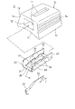
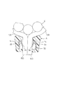
図1は本発明の実施例による結束具Aの分解斜視図、図2は同実施例による結束具Aの断面図である。この結束具Aのボディ10はナイロンやアセタール樹脂などでなる合成樹脂成形体で構成されているので、強靱でしかも耐候性に優れたものである。ボディ10は台形状に形成されていて、その表面と裏面とに亘る矩形の貫通孔11を有すると共に、左右の両側面に亘りかつ上記貫通孔11を横切る形に開設された取付孔12を有している。図2で判るように、貫通孔11は2重に重ね合わされた結束用帯体100をそれほど大きな遊び空間を持たさずに挿通できる広さになっている。また、ボディ10の傾斜した側面13,13には凹凸面14,14が具備されていて、結束作業時にこの凹凸面14,14を手で掴むようにすれば、その凹凸面14,14による滑止め作用と側面13,13の傾斜とによって手が滑りにくいようになっている。また、ボディ10の裏面は凹入面15になっており、後述する被結束体とのなじみ性が高められるようになっている。
FIG. 1 is an exploded perspective view of a binding device A according to an embodiment of the present invention, and FIG. 2 is a cross-sectional view of the binding device A according to the embodiment. Since the
ボディ10の取付孔12には金属製の枠体30が挿入されて保持される。この実施例の枠体30は発錆のおそれがきわめて少なく長期に亘って必要強度を維持し得る金属、たとえばステンレス鋼によって構成されている。この枠体30は、矩形の基板部31とこの基板部31の両端部から立ち上げられた一対の側板部32,32とによってコ字形に形成されている。そして、基板部31を切り起こすことによって弾性を備えた一対の係止爪33,33が相対向状に形成されている。一対の係止爪33,33は対称形状であって、先窄まり状に傾斜しており、また、図1に拡大して示したように、係止爪33の先端部34にはエッジ状の喰込み歯が具備されている。そして、図2で判るように、一対の係止爪33,33の先端部34,34の相互間隔Tは、結束用帯体100の2重の重なり厚さt2よりもやゝ狭い広さであり、また、一枚(1重)の帯体100の厚さt1に比べるとその2倍よりは狭いが2倍に近い広さになっている。上記基板部31における係止爪33,33の切起し跡によって形成された矩形の開口35は、その縦横が上述したボディ10の貫通孔11の縦横よりも長くなっている。
A
枠体30はボディ10の取付孔12に圧入などの手段で挿入されて保持される。図2で判るように、取付孔12に枠体30を挿入した状態では、枠体30の開口35がボディ10の貫通孔11を完全に含んでしまう。このように構成された結束具Aにおいては、一対の係止爪33,33がボディ10の貫通孔11の孔内に傾斜姿勢でかつ対称に突き出ている。
The
次に、結束作業を説明する。 Next, the binding operation will be described.
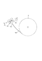
図3のようにリールRから引き出した合成樹脂製の結束用帯体100の先端部140に結束具Aを貫通孔11(図2参照)を利用して矢印dのように差し込む。言い換えると、帯体100の先端部140が、結束具Aにおける一対の係止爪33,33の先端からその基端に向く方向すなわち一対の係止爪33,33の末拡がり方向Xに沿って貫通孔11に差し込まれる。この作業は、2重に重ね合わされた結束用帯体100をそれほど大きな遊び空間を持たさずに挿通できる広さになっている貫通孔11に対して行う作業であるから、先端部140を貫通孔11に遊嵌挿するというきわめて容易な作業である。
As shown in FIG. 3, the binding tool A is inserted into the
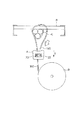
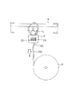
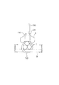
この後、帯体100を貫通孔11(図2参照)から長く引き出し、図4のように、被結束体たとえば図例の電力ケーブルCとそれが載架されているケーブルラックBに襷掛けなどの形に掛け回す。電力ケーブルCとケーブルラックBとに掛け回した帯体100の上記先端部140を、図5のように帯体100が既に挿通されている上記貫通孔11(図2参照)に臨ませ、次に、帯体100の先端部140を貫通孔11(図2参照)に一対の係止爪33,33の先窄まり方向Yに差し込んで挿通させることにより、その帯体100の先端部140をボディ10から少しだけ突出させる。このようにすると、貫通孔11(図2参照)に帯体が2重に重なり合って挿通された状態になり、2重に重なり合っている帯体100のそれぞれに一対の係止爪33,33の先端部34,34が各別に係止する。帯体100の先端部140のボディ10からの突出長さは、たとえば、帯体100に対する係止爪33の喰込み位置が喰い込んだまま少ししずれてもその先端部140が係止爪33から離脱しない程度の長さにしておけばよく、安全性を見越した長さにしておくことが望まれる。2重に重なり合っている帯体100のそれぞれに一対の係止爪33,33の先端部34,34が各別に係止した状態では、帯体100の先端部140が引き抜かれる方向、すなわち一対の係止爪33,33の先窄まり方向Y(図5参照)には結束具Aが動かないけれども、貫通孔11(図2参照)への挿入始部側の帯体100を引っ張って締め付ける方向(図6の矢印e)へは結束具Aをスライドして動かすことが可能である。したがって、ボディ10の凹凸面14,14を片手で掴み、他の片手で図6のように帯体100における貫通孔11(図2参照)への挿入始部側を矢印eのように引っ張って帯体100を締め付け、その後、図7のようにその帯体100をカットしてその切断端150を上記先端部140に揃えることにより結束が行われる。
Thereafter, the
図8は結束後における一対の係止爪33,33と帯体100との係止状態を例示している。同図のように、一対の係止爪33,33のエッジ状の先端部34,34が2重に重なり合った帯体100のそれぞれに各別に喰い込んで抜け落ちを防いでいる。
FIG. 8 illustrates a locked state between the pair of locking
この実施例において、ボディ10はアセタール樹脂で成形されているので、耐候性に優れて長期に亘ってボディ10が高強度を保ち、しかも一対の係止爪が発錆のおそれの少ないステンレス鋼で作られているので経時により錆びて抜止め作用が損なわれるという事態が生じにくい。これらのことより、この実施例の結束具によると長期に亘って安定した結束強度が持続するという作用が発揮される。
In this embodiment, since the
本発明において、一対の係止爪33,33はボディ10を成形するときにボディ10に埋設されていてもよい。また、被結束体には上記した電力ケーブルCやケーブルラックBの他に、屋内外に架設される電設ケーブルやその他の産業分野たとえば運搬や包装の分野での取扱物などがある。
In the present invention, the pair of locking
A 結束具
10 ボディ
11 貫通孔
12 取付孔
30 枠体
33 係止爪
34 係止爪の先端部
35 開口
100 帯体
T 係止爪の先端部の相互間隔
t2 帯体の2重の重なり厚さ
Reference Signs List A Attaching
Claims (1)
上記係止爪が挿入して保持される取付孔が、ボディにその貫通孔を横切って開設されていることを特徴とする結束具。
A pair of resilient metal locking claws are provided in a body having a through-hole large enough to allow a double-stacked binding band to pass therethrough and projecting into the through-hole and having elasticity. The pair of locking claws are inclined so as to be tapered in the hole, and the distance between the tips of the pair of locking claws that can be locked to the band is such that the band is one. It is a binding device that is wide enough to be loosely inserted in the weight, and is slightly smaller than the double overlapping thickness.
A tying device, wherein a mounting hole into which the locking claw is inserted and held is formed in the body across the through hole.
Priority Applications (1)
| Application Number | Priority Date | Filing Date | Title |
|---|---|---|---|
| JP2004030238A JP2004155507A (en) | 2004-02-06 | 2004-02-06 | Bundling tool |
Applications Claiming Priority (1)
| Application Number | Priority Date | Filing Date | Title |
|---|---|---|---|
| JP2004030238A JP2004155507A (en) | 2004-02-06 | 2004-02-06 | Bundling tool |
Related Parent Applications (1)
| Application Number | Title | Priority Date | Filing Date |
|---|---|---|---|
| JP11848294A Division JP3548600B2 (en) | 1994-05-31 | 1994-05-31 | Tying tool |
Publications (1)
| Publication Number | Publication Date |
|---|---|
| JP2004155507A true JP2004155507A (en) | 2004-06-03 |
Family
ID=32822063
Family Applications (1)
| Application Number | Title | Priority Date | Filing Date |
|---|---|---|---|
| JP2004030238A Pending JP2004155507A (en) | 2004-02-06 | 2004-02-06 | Bundling tool |
Country Status (1)
| Country | Link |
|---|---|
| JP (1) | JP2004155507A (en) |
Cited By (2)
| Publication number | Priority date | Publication date | Assignee | Title |
|---|---|---|---|---|
| JP2009001316A (en) * | 2007-06-22 | 2009-01-08 | Hellermann Tyton Co Ltd | Transparent and high strength fastening band, fastening band kit, head for fastening band and strap for fastening band |
| JP2016125530A (en) * | 2014-12-26 | 2016-07-11 | 未来工業株式会社 | Attachment body, attachment tool, and wiring and piping material fixation device |
-
2004
- 2004-02-06 JP JP2004030238A patent/JP2004155507A/en active Pending
Cited By (2)
| Publication number | Priority date | Publication date | Assignee | Title |
|---|---|---|---|---|
| JP2009001316A (en) * | 2007-06-22 | 2009-01-08 | Hellermann Tyton Co Ltd | Transparent and high strength fastening band, fastening band kit, head for fastening band and strap for fastening band |
| JP2016125530A (en) * | 2014-12-26 | 2016-07-11 | 未来工業株式会社 | Attachment body, attachment tool, and wiring and piping material fixation device |
Similar Documents
| Publication | Publication Date | Title |
|---|---|---|
| US8739387B1 (en) | Reusable cable tie | |
| US8474104B2 (en) | Cable tie | |
| US10604317B2 (en) | Reusable tie strap with multiple apertures | |
| JP3421261B2 (en) | Improved cable tie with locking head and separate strap | |
| US6516498B2 (en) | Clamps | |
| JP3984867B2 (en) | Cable tie for wire harness branch | |
| US10882674B2 (en) | Tie-wrap assembly and method for using the same | |
| JP2007504064A (en) | Cable ties | |
| JP6463834B2 (en) | Fasteners with reusable insert elements | |
| JP2004155507A (en) | Bundling tool | |
| JP3548600B2 (en) | Tying tool | |
| US20180187703A1 (en) | Tie-wrap assembly and method for using the same | |
| KR200483892Y1 (en) | Cable tie | |
| BR112015023243B1 (en) | CABLE BAND FIXING DEVICES AND METHODS OF USING THEM | |
| JPH0735269A (en) | Binding band | |
| JP4291920B2 (en) | Binders such as electric wires | |
| JPS5852210Y2 (en) | cable tie buckle | |
| JP4303066B2 (en) | Stopper and binding device using the same | |
| KR102432945B1 (en) | Automotive wire bundle fixture | |
| JPS623589Y2 (en) | ||
| US20240034530A1 (en) | Cable tie | |
| KR20130051034A (en) | Cable tie | |
| JPH0741037A (en) | Binding tie | |
| WO2002006714A1 (en) | Flexible locking tie | |
| KR20100005299A (en) | A cable tie |