JP2004155303A - Braking force control device for vehicle - Google Patents
Braking force control device for vehicle Download PDFInfo
- Publication number
- JP2004155303A JP2004155303A JP2002322595A JP2002322595A JP2004155303A JP 2004155303 A JP2004155303 A JP 2004155303A JP 2002322595 A JP2002322595 A JP 2002322595A JP 2002322595 A JP2002322595 A JP 2002322595A JP 2004155303 A JP2004155303 A JP 2004155303A
- Authority
- JP
- Japan
- Prior art keywords
- braking
- braking force
- steering
- collision avoidance
- collision
- Prior art date
- Legal status (The legal status is an assumption and is not a legal conclusion. Google has not performed a legal analysis and makes no representation as to the accuracy of the status listed.)
- Pending
Links
Images


Abstract
Description
【0001】
【発明の属する技術分野】
本発明は、車輌用制動力制御装置に係り、更に詳細には前方障害物との衝突の可能性に応じて制動力を制御する車輌用制動力制御装置に係る。
【0002】
【従来の技術】
前方障害物との衝突の可能性がある状況に於いて制動力を制御する自動車等の車輌の制動力制御装置の一つとして、例えば本願出願人の出願にかかる下記の特許文献1に記載されている如く、前方障害物との衝突の可能性がある場合に自動的に制動を行う制動力制御装置が従来より知られている。特に下記の特許文献1に記載された制動力制御装置に於いては、アンチスキッド制御装置が故障しているときには、自動制動を行うタイミングを早くすると共に、制動圧を通常時よりも低くするようになっている。
【特許文献1】
特開平7−69201号公報
【0003】
【発明が解決しようとする課題】
一般に、前方障害物との衝突の可能性がある状況に於いて、車輌が前方障害物との衝突を回避する方法として、操舵により前方障害物とは異なる方向へ車輌を導く方法と、制動により車輌を減速させて車輌が前方障害物まで至らないようにする方法と、これらの組合せによる方法とがある。
【0004】
また一般に、前方障害物との衝突の可能性があるか否かは前方障害物に対する自車の相対速度及び前方障害物までの距離(相対距離)により判定可能であるが、相対速度及び相対距離の関係で見た場合に於ける操舵による衝突回避が可能な領域及び制動による衝突回避が可能な領域は一致していない。即ち前方障害物との衝突の可能性がある状況に於いて、操舵による衝突回避は可能であるが制動による衝突回避は不可能である領域や、制動による衝突回避は可能であるが操舵による衝突回避は不可能である領域が存在する。
【0005】
特に制動による衝突回避が行われる場合には、車輪の制動力、即ち前後力が増大されることによって車輪の横力の余裕度が低下するので、制動による衝突回避が行われることにより操舵輪の横力(コーナリングフォース)が低下されることに起因して操舵による衝突回避を効果的に行うことができなくなる場合があり、逆に操舵による衝突回避が効果的に行われるよう制動力が制限されると、車輌を効果的に減速させることができなくなる。従って操舵及び制動による衝突回避可能性の状況に応じて車輪に付与される制動力が適正に制御される必要がある。
【0006】
しかるに上記特許文献1に記載された制動力制御装置の如き従来の制動力制御装置に於いては、操舵及び制動による衝突回避可能性の状況に応じて車輪に付与される制動力が適正に制御される必要があることについては全く考慮されていないため、衝突回避可能性の状況に応じて車輪に付与される制動力を適正に制御することができず、従って車輌の衝突回避の効果を向上させる上で改善の余地がある。
【0007】
本発明は、前方障害物との衝突の可能性がある状況に於いて制動力を制御する従来の制動力制御装置に於ける上述の如き問題に鑑みてなされたものであり、本発明の主要な課題は、操舵及び制動による衝突回避可能性の状況に応じて制動力を制御することにより、従来に比して車輌の衝突回避の効果を向上させることである。
【0008】
【課題を解決するための手段】
上述の主要な課題は、本発明によれば、請求項1の構成、即ち前方障害物との衝突の可能性に応じて制動力を制御する車輌用制動力制御装置に於いて、衝突の可能性があると判定された場合には操舵による衝突回避可能性の度合若しくは制動による衝突回避可能性の度合に応じて運転者の制動操作量又は制動力制御目標値に対する実制動力の比を変更することを特徴とする車輌用制動力制御装置によって達成される。
【0009】
また本発明によれば、上述の主要な課題を効果的に達成すべく、上記請求項1の構成に於いて、操舵による衝突回避可能性の度合が低いときにはそれが高いときに比して前記制動力の比を高く変更するよう構成される(請求項2の構成)。
【0010】
また本発明によれば、上述の主要な課題を効果的に達成すべく、上記請求項1又は2の構成に於いて、操舵による衝突回避可能性の度合及び制動による衝突回避可能性の度合が高いときには操舵による衝突回避可能性の度合若しくは制動による衝突回避可能性の度合が低いときに比して前記制動力の比を低く変更するよう構成される(請求項3の構成)。
【0011】
また本発明によれば、上述の主要な課題を効果的に達成すべく、上記請求項2の構成に於いて、アンチスキッド制御に於いて許容される制動スリップ率を高くし若しくはアンチスキッド制御が開始され難くすることにより前記制動力の比を高く変更するよう構成される(請求項4の構成)。
【0012】
また本発明によれば、上述の主要な課題を効果的に達成すべく、上記請求項2の構成に於いて、前輪に対する後輪の制動スリップ率又は運転者の制動操作量が基準値以上であるときには前輪に対する後輪の制動力の比を低下させる前後輪制動力配分制御に於いて、前記基準値を高くすることにより前記制動力の比を高く変更するよう構成される(請求項5の構成)。
【0013】
また本発明によれば、上述の主要な課題を効果的に達成すべく、上記請求項3の構成に於いて、アンチスキッド制御に於いて許容される制動スリップ率を低くし若しくはアンチスキッド制御が開始され易くすることにより前記制動力の比を低く変更するよう構成される(請求項6の構成)。
【0014】
また本発明によれば、上述の主要な課題を効果的に達成すべく、上記請求項3の構成に於いて、前輪に対する後輪の制動スリップ率又は運転者の制動操作量が基準値以上であるときには前輪に対する後輪の制動力の比を低下させる前後輪制動力配分制御に於いて、前記基準値を低くすることにより前記制動力の比を低く変更するよう構成される(請求項7の構成)。
【0015】
【発明の作用及び効果】
上記請求項1の構成によれば、衝突の可能性があると判定された場合には操舵による衝突回避可能性の度合若しくは制動による衝突回避可能性の度合に応じて運転者の制動操作量又は制動力制御目標値に対する実制動力の比が変更されるので、操舵による衝突回避可能性の度合や制動による衝突回避可能性の度合が考慮されない従来の制動力制御装置の場合に比して、衝突回避可能性の状況に応じて車輪に付与される制動力を適正に制御することができ、これにより車輌の衝突回避の効果を向上させることができる。
【0016】
また一般に、操舵による衝突回避可能性の度合が低いときには、車輪の制動力が増大されても操舵による衝突回避の効果はそれほど低下せず、車輪の制動力を増大させて車輌をできるだけ効果的に減速させた方が衝突回避の可能性が高くなり、或いは衝突の影響を低減することができる。
【0017】
上記請求項2の構成によれば、操舵による衝突回避可能性の度合が低いときにはそれが高いときに比して前記制動力の比が高く変更されるので、操舵による衝突回避の効果を大きく低下させることなく車輌をできるだけ効果的に減速させることができ、これにより衝突回避の可能性を高くし或いは衝突の影響を低減することができる。
【0018】
また上記請求項3の構成によれば、操舵による衝突回避可能性の度合及び制動による衝突回避可能性の度合が高いときには操舵による衝突回避可能性の度合若しくは制動による衝突回避可能性の度合が低いときに比して前記制動力の比が低く変更されるので、車輪の制動力が過大に増大されることに起因して操舵による衝突回避の効果が低下することを防止し、これにより操舵による衝突回避の効果を確実に確保することができる。
【0019】
また上記請求項4の構成によれば、アンチスキッド制御に於いて許容される制動スリップ率を高くし若しくはアンチスキッド制御が開始され難くすることにより前記制動力の比が高く変更されるので、アンチスキッド制御により車輌の挙動が悪化することを防止しつつ車輪の制動力を高くして車輌を効果的に減速させることができ、前記基準値が高くされない場合に比して制動による衝突回避の効果を向上させることができる。
【0020】
また上記請求項5の構成によれば、前輪に対する後輪の制動スリップ率又は運転者の制動操作量が基準値以上であるときには前輪に対する後輪の制動力の比を低下させる前後輪制動力配分制御に於いて、前記基準値を高くすることにより前記制動力の比が高く変更されるので、前後輪制動力配分制御により車輌の挙動が悪化することを防止しつつ後輪の制動力を高くして車輌を効果的に減速させることができ、前記基準値が高くされない場合に比して制動による衝突回避の効果を向上させることができる。
【0021】
また上記請求項6の構成によれば、アンチスキッド制御に於いて許容される制動スリップ率を低くし若しくはアンチスキッド制御が開始され易くすることにより前記制動力の比が低く変更されるので、アンチスキッド制御により車輌の挙動が悪化することを効果的に防止しつつ車輪の制動力が過剰になることを確実に防止することができ、前記基準値が低くされない場合に比して操舵による衝突回避の効果を向上させることができる。
【0022】
また上記請求項7の構成によれば、前輪に対する後輪の制動スリップ率又は運転者の制動操作量が基準値以上であるときには前輪に対する後輪の制動力の比を低下させる前後輪制動力配分制御に於いて、前記基準値を低くすることにより前記制動力の比が低く変更されるので、前後輪制動力配分制御により後輪の制動力が過剰になることを確実に防止し車輌の挙動が悪化することを効果的に防止することができ、前記基準値が低くされない場合に比して操舵による衝突回避の効果を向上させることができる。
【0023】
【課題解決手段の好ましい態様】
本発明の一つの好ましい態様によれば、上記請求項1乃至7の構成に於いて、前方障害物までの距離及び前方障害物に対する自車の相対速度に基づき前方障害物との衝突の可能性を判定するよう構成される(好ましい態様1)。
【0024】
本発明の他の一つの好ましい態様によれば、上記請求項1乃至7の構成に於いて、前方障害物に対する自車の相対速度に基づき操舵による衝突回避限界距離を推定し、前方障害物までの距離と操舵による衝突回避限界距離との差が大きいほど操舵による衝突回避可能性の度合が高いと判定するよう構成される(好ましい態様2)。
【0025】
本発明の他の一つの好ましい態様によれば、上記請求項1乃至7の構成に於いて、前方障害物に対する自車の相対速度に基づき制動による衝突回避限界距離を推定し、前方障害物までの距離と制動による衝突回避限界距離との差が大きいほど制動による衝突回避可能性の度合が高いと判定するよう構成される(好ましい態様3)。
【0026】
本発明の他の一つの好ましい態様によれば、上記請求項1乃至7の構成に於いて、衝突の可能性があると判定された場合に於いて運転者により操舵が行われていないときには、操舵による衝突回避可能性の度合及び制動による衝突回避可能性の度合に拘わらず前記制動力の比を高く変更するよう構成される(好ましい態様4)。
【0027】
本発明の他の一つの好ましい態様によれば、上記請求項2の構成に於いて、前方障害物に対する自車の相対速度に基づき操舵による衝突回避限界距離を推定し、前方障害物までの距離が操舵による衝突回避限界距離未満であるときには前方障害物までの距離が操舵による衝突回避限界距離以上であるときに比して前記制動力の比を高く変更するよう構成される(好ましい態様5)。
【0028】
本発明の他の一つの好ましい態様によれば、上記請求項3の構成に於いて、前方障害物に対する自車の相対速度に基づき操舵による衝突回避限界距離及び制動による衝突回避限界距離を推定し、前方障害物までの距離が操舵による衝突回避限界距離以上であり且つ制動による衝突回避限界距離以上であるときには、前方障害物までの距離が操舵による衝突回避限界距離未満若しくは制動による衝突回避限界距離未満であるときに比して、前記制動力の比を低く変更するよう構成される(好ましい態様6)。
【0029】
本発明の他の一つの好ましい態様によれば、上記請求項1の構成に於いて、操舵による衝突回避可能性の度合は高いが制動による衝突回避可能性の度合が低いときには、前記制動力の比を操舵による衝突回避可能性の度合が低いときよりも低く且つ制動による衝突回避可能性の度合が高いときよりも高く変更するよう構成される(好ましい態様7)。
【0030】
本発明の他の一つの好ましい態様によれば、上記好ましい態様7の構成に於いて、前方障害物に対する自車の相対速度に基づき操舵による衝突回避限界距離及び制動による衝突回避限界距離を推定し、前方障害物までの距離が操舵による衝突回避限界距離以上であり且つ制動による衝突回避限界距離未満であるときには、前記制動力の比を前方障害物までの距離が操舵による衝突回避限界距離未満であるときに比して低く且つ前方障害物までの距離が制動による衝突回避限界距離以上であるときに比して高く変更するよう構成される(好ましい態様8)。
【0031】
本発明の他の一つの好ましい態様によれば、上記請求項4の構成に於いて、アンチスキッド制御に於ける制動スリップ率の基準値を高くすることにより、許容される制動スリップ率を高くし若しくはアンチスキッド制御が開始され難くするよう構成される(好ましい態様9)。
【0032】
本発明の他の一つの好ましい態様によれば、上記請求項6の構成に於いて、アンチスキッド制御に於ける制動スリップ率の基準値を低くすることにより、許容される制動スリップ率を低くし若しくはアンチスキッド制御が開始され易くするよう構成される(好ましい態様10)。
【0033】
【発明の実施の形態】
以下に添付の図を参照しつつ、本発明を幾つかの好ましい実施形態(以下単に実施形態という)について詳細に説明する。
【0034】
第一の実施形態
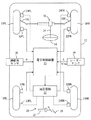
図1はアンチスキッド制御が行われる車輌に適用され衝突防止装置として構成された本発明による車輌用制動力制御装置の第一の好ましい実施形態を示す概略構成図である。
【0035】
図1に於て、10FL及び10FRはそれぞれ車輌12の左右の前輪を示し、10RL及び10RRはそれぞれ車輌の駆動輪である左右の後輪を示している。従動輪であり操舵輪でもある左右の前輪10FL及び10FRは運転者によるステアリングホイール14の転舵に応答して駆動されるラック・アンド・ピニオン式のパワーステアリング装置16によりタイロッド18L 及び18R を介して操舵される。
【0036】
各車輪の制動力は制動装置20の油圧回路22によりホイールシリンダ24FR、24FL、24RR、24RLの制動圧が制御されることによって制御されるようになっている。図には示されていないが、油圧回路22はリザーバ、オイルポンプ、種々の弁装置等を含み、各ホイールシリンダの制動圧は通常時には運転者によるブレーキペダル26の踏み込み操作に応じて駆動されるマスタシリンダ28により制御され、また必要に応じて後に詳細に説明する如く電子制御装置30により制御される。
【0037】
車輪10FR〜10RLにはそれぞれ対応する車輪の車輪速度Vwi(i=fr、fl、rr、rl)を周速度として検出する車輪速度センサ32FR〜32RLが設けられ、ステアリングコラムにはステアリングシャフト34の回転角を操舵角θとして検出する操舵角センサ36が設けられている。また車輌12には例えばレーザ光や電波を利用して前方障害物までの距離L及び前方障害物に対する自車の相対速度Vreを検出するレーダーセンサ38が設けられている。尚操舵角センサ36は車輌の右旋回方向を正として操舵角を検出する。
【0038】
図示の如く、車輪速度センサ32FR〜32RLにより検出された車輪速度Vwiを示す信号、操舵角センサ36により検出された操舵角θを示す信号、レーダーセンサ38により検出された前方障害物までの距離L及び前方障害物に対する相対速度Vreを示す信号は電子制御装置30に入力される。尚図には詳細に示されていないが、電子制御装置30は例えばCPUとROMとRAMと入出力ポート装置とを有し、これらが双方向性のコモンバスにより互いに接続された一般的な構成のマイクロコンピュータを含んでいる。
【0039】
電子制御装置30は、図2に示されたフローチャートに従い、レーダーセンサ38により検出された前方障害物までの距離L及び前方障害物に対する自車の相対速度Vreに基づき前方障害物との衝突の虞れを判定し、前方障害物との衝突の虞れがあるときには前方障害物までの距離L及び相対速度Vreに基づき操舵による衝突回避可能性及び制動による衝突回避可能性を判定し、その判定結果に応じてアンチスキッド制御(ABS制御)の開始基準値を可変制御する。
【0040】
また電子制御装置30は、図3に示されたフローチャートに従い、各車輪の車輪速度Vwiに基づき当技術分野に於いて公知の要領にて車体速度Vb及び各車輪の制動スリップ率SLi(i=fl、fr、rl、rr)を演算し、何れかの車輪の制動スリップ率SLiがアンチスキッド制御の開始基準値よりも大きくなり、アンチスキッド制御の開始条件が成立すると、アンチスキッド制御の終了条件が成立するまで、当該車輪について制動スリップ率が所定の範囲内になるようホイールシリンダ内の圧力を増減するアンチスキッド制御を行う。
【0041】
次に図2に示されたフローチャートを参照して第一の実施形態に於けるアンチスキッド制御の開始基準値変更制御ルーチンについて説明する。尚図2に示されたフローチャートによる制御は図には示されていないイグニッションスイッチの閉成により開始され、所定の時間毎に繰返し実行される。
【0042】
まずステップ10に於いては操舵角センサ36により検出された操舵角θを示す信号等の読み込みが行われ、ステップ20に於いては前方障害物との衝突の虞れがあるか否かの判別が行われ、否定判別が行われたときにはステップ60へ進み、肯定判別が行われたときにはステップ30へ進む。
【0043】
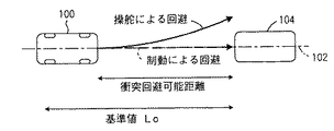
この場合、前方障害物との衝突の虞れがあるか否かの判別は当技術分野に於いて公知の任意の態様にて行われてよく、例えば図4に示されている如く、レーダーセンサ38により自車100の走行路102の前方に障害物104が検出された場合に於いて、前方障害物104に対する自車100の相対速度Vreが大きいほど小さい基準値Loが演算され、前方障害物104までの距離Lが基準値Lo以下であるときに衝突の虞れがあると判定されてよい。尚図4の実線の矢印は操舵による衝突の回避を示し、破線の矢印は制動による衝突の回避を示している。
【0044】
ステップ30に於いては例えば操舵角θの微分値θdが演算されると共に、操舵角θの大きさ及び微分値θdの大きさがそれぞれ基準値以上であるか否かの判別により運転者により操舵が行われているか否かの判別が行われ、否定判別が行われたときにはステップ80へ進み、肯定判別が行われたときにはステップ40へ進む。尚運転者により操舵が行われているか否かの判別は車輌のヨーレート若しくは横加速度又はこれらの何れかと操舵角θ若しくは微分値θdとの組合せに基づいて行われてもよい。
【0045】
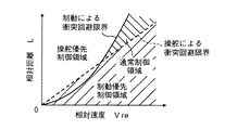
ステップ40に於いてはレーダーセンサ38により検出された前方障害物までの距離L及び相対速度Vreに基づき、操舵による衝突回避が可能であるか否かの判別が行われ、否定判別が行われたときにはステップ80へ進み、肯定判別が行われたときにはステップ50へ進む。例えば図5の実線は操舵による衝突回避可能限界を示しており、距離Lが操舵による衝突回避可能限界よりも大きい場合に操舵による衝突回避が可能であると判定される。
【0046】
ステップ50に於いてはレーダーセンサ38により検出された前方障害物までの距離L及び相対速度Vreに基づき、制動による衝突回避が可能であるか否かの判別が行われ、否定判別が行われたときにはステップ60へ進み、肯定判別が行われたときにはステップ70へ進む。例えば図5の破線は制動による衝突回避可能限界を示しており、距離Lが制動による衝突回避可能限界よりも大きい場合に制動による衝突回避が可能であると判定される。
【0047】
ステップ60に於いては基準値SLoが通常時の値SLon(正の定数)に設定され、ステップ70に於いてはアンチスキッド制御が早めに開始されると共に許容される制動スリップ率が低くなるよう、後述のアンチスキッド制御の開始判定に於ける制動スリップ率SLiの基準値SLoが通常時の値SLonよりも小さい操舵優先制御時の値SLos(正の定数)に設定され、ステップ80に於いてはアンチスキッド制御が開始され難くなるよう、基準値SLoが通常時の値SLonよりも大きい制動優先制御時の値SLob(正の定数)に設定される。
【0048】
次に図3に示されたフローチャートを参照して第一の実施形態に於けるアンチスキッド制御ルーチンについて説明する。尚図2に示されたフローチャートによる制御も図には示されていないイグニッションスイッチの閉成により開始され、例えば左前輪、右前輪、左後輪、右後輪の順に繰り返し実行される。
【0049】
まずステップ210に於いては車輪速度センサ32FR〜32RLにより検出された車輪速度Vwiを示す信号等の読み込みが行われ、ステップ220に於いては車輪速度Vwiに基づき当技術分野に於いて公知の要領にて推定車体速度Vwbが演算され、ステップ230に於いては各車輪について推定車体速度Vb及び各車輪の車輪速度Vwiに基づきこれらの偏差を推定車体速度Vwbにて除算した値として制動スリップ率SLi(i=fl、fr、rl、rr)が演算される。
【0050】
ステップ240に於いては当該車輪についてアンチスキッド制御が行われているか否かの判別が行われ、肯定判別が行われたときにはステップ260へ進み、否定判別が行われたときにはステップ250へ進む。
【0051】
ステップ250に於いては例えば推定車体速度Vbが制御開始基準値Vbs(正の定数)以上であり且つ当該車輪の制動スリップ率SLiが上述の図2に示されたフローチャートに従って設定された基準値SLo以上であるか否かの判別により、当該車輪についてアンチスキッド制御の開始条件が成立しているか否かの判別が行われ、否定判別が行われたときにはそのまま図3に示された制御ルーチンを一旦終了し、肯定判別が行われたときにはステップ270へ進む。
【0052】
ステップ260に於いては当該車輪についてアンチスキッド制御の終了条件が成立しているか否かの判別が行われ、肯定判別が行われたときにはそのまま図3に示された制御ルーチンを一旦終了し、否定判別が行われたときにはステップ270へ進む。
【0053】
ステップ270に於いては例えば車輪速度Vwiの時間微分値として演算される車輪加速度及び車輪の制動スリップ率SLiに基づき当技術分野に於いて公知の要領にて制御モードが増圧モード、保持モード、減圧モードの何れかに決定される。
【0054】
ステップ280に於いては例えば図には示されていない前後加速度センサにより検出された車輌の前後加速度Gxに基づき演算される車輌の減速度Gxb、制御モード、車輪の制動スリップ率SLiに基づき各車輪の増減圧制御弁の目標デューティ比Dti(i=fl、fr、rl、rr)が演算され、ステップ290に於いては目標デューティ比Dtiに応じて各車輪の増減圧制御弁がデューティ比制御されることにより、各車輪の制動圧が適正な値になるよう制御される。
【0055】
かくして図示の第一の実施形態によれば、ステップ20に於いて前方障害物との衝突の虞れがあると判定されると、ステップ30に於いて運転者により操舵が行われているか否かの判別が行われ、運転者により操舵が行われているときにはステップ40及び50に於いてそれぞれ操舵による衝突回避が可能であるか否かの判別及び制動による衝突回避が可能であるか否かの判別が行われる。
【0056】
運転者により操舵が行われていない場合や運転者により操舵が行われているが操舵による衝突回避が不可能である場合には、ステップ80に於いてアンチスキッド制御が開始され難くなるよう、アンチスキッド制御に於ける制動スリップ率SLiの基準値SLoが通常時の値SLonよりも大きい制動優先制御時の値SLobに設定され、運転者により操舵が行われており操舵による衝突回避が可能であるが制動による衝突回避が不可能である場合には、ステップ60に於いて基準値SLoが通常時の値SLonに設定され、運転者により操舵が行われており操舵による衝突回避及び制動による衝突回避の何れも可能である場合には、ステップ70に於いてアンチスキッド制御が早めに開始されると共に許容される制動スリップ率が低くなるよう、基準値SLoが通常時の値SLonよりも小さい操舵優先制御時の値SLosに設定される。
【0057】
従って前方障害物との衝突の虞れがある状況に於いて、操舵による衝突回避が可能であるか否か及び制動による衝突回避が可能であるか否かに応じてアンチスキッド制御を適正に実行することができ、特に操舵による衝突回避が可能である場合には、アンチスキッド制御が開始され易くして許容される制動スリップ率を低くし、できるだけ車輪の横力の低下を抑制して効果的に操舵による衝突回避効果を向上させることができ、また操舵による衝突回避が不可能である場合には、アンチスキッド制御が開始され難くして許容される制動スリップ率を高くし、できるだけ効果的に制動力を発生させて制動による衝突回避効果を向上させ、或いは衝突の影響をできるだけ低減することができる。
【0058】
特に図示の第一の実施形態によれば、ステップ30に於いて運転者により操舵が行われているか否かの判別が行われ、運転者により操舵が行われていないときには、操舵による衝突回避及び制動による衝突回避が可能であるか否かに拘わらずステップ80に於いて基準値SLoが制動優先制御時の値SLobに設定されるので、運転者により操舵が行われているか否かの判別が行われることなくステップ40以降が実行される場合に比して、運転者により操舵が行われていない状況に於ける車輌の衝突回避効果を向上させることができる。
【0059】
第一及び第二の修正例
図7及び図8はそれぞれ第一の実施形態の第一及び第二の修正例に於けるアンチスキッド制御の開始基準値変更制御ルーチンを示すフローチャートである。尚図7及び図8に於いて図2に示されたステップと同一のステップには図2に於いて付されたステップ番号と同一のステップ番号が付されている。
【0060】
図7に示された第一の修正例に於いては、上述の第一の実施形態に於けるステップ50に対応する判別は実行されず、ステップ40に於いて肯定判別が行われたときにはステップ60へ進み、制動スリップ率SLiの基準値SLoが通常時の値SLonに設定される。
【0061】
従って図示の第一の修正例によれば、制動による衝突回避が可能であるか否かの判別が行われず、運転者により操舵が行われており操舵による衝突回避が可能である場合には、基準値SLoが通常時の値SLonに設定されるので、前方障害物との衝突の虞れがある状況に於いて、操舵による衝突回避が可能であるか否かに応じてアンチスキッド制御を適正に実行することができ、また上述の第一の実施形態の場合に比して簡便にアンチスキッド制御を実行することができる。
【0062】
図8に示された第二の修正例に於いては、ステップ20〜40に於いてそれぞれ否定判別が行われた場合にもステップ60に於いて制動スリップ率SLiの基準値SLoが通常時の値SLonに設定され、運転者により操舵が行われていない場合や操舵による衝突回避が不可能である場合にも、基準値SLoは通常時の値SLonよりも大きい制動優先制御時の値SLobに設定されない。
【0063】
従って図示の第二の修正例によれば、前方障害物との衝突の虞れがある状況に於いて、操舵による衝突回避が可能であるか否か及び制動による衝突回避が可能であるか否かに応じてアンチスキッド制御を適正に実行することができ、また上述の第一の実施形態の場合に比して簡便にアンチスキッド制御を実行することができる。
【0064】
第二の実施形態
図9は前後輪制動力配分制御装置として構成された本発明による車輌用制動力制御装置の第二の実施形態に於ける前後輪制動力配分制御の基準値変更制御ルーチンを示すフローチャート、図10は第二の実施形態に於ける前後輪制動力配分制御ルーチンを示すフローチャートである。尚図9及び図10に示されたフローチャートによる制御も図には示されていないイグニッションスイッチの閉成により開始され、所定の時間毎に繰返し実行される。また図9に於いて図2に示されたステップと同一のステップには図2に於いて付されたステップ番号と同一のステップ番号が付されている。
【0065】
この実施形態に於いては、電子制御装置30は前輪に対する後輪のスリップ率SLrを演算し、該スリップ率SLrが基準値SLro未満であるときには油圧回路22を制御することによってマスタシリンダ28と各車輪のホイールシリンダ24FL〜24RRを連通接続して各車輪の制動圧をマスタシリンダ圧Pmに制御し、スリップ率SLrが基準値SLro以上であるときには左右後輪のホイールシリンダ24RL及び24RRとマスタシリンダ28との連通を遮断することにより、後輪の制動圧を保持する前後輪制動力配分制御を行う。
【0066】
またこの実施形態に於ける電子制御装置30は、図9に示されたフローチャートに従い、レーダーセンサ38により検出された前方障害物までの距離L及び前方障害物に対する自車の相対速度Vreに基づき前方障害物との衝突の虞れを判定し、前方障害物との衝突の虞れがあるときには前方障害物までの距離L及び相対速度Vreに基づき操舵による衝突回避可能性及び制動による衝突回避可能性を判定し、その判定結果に応じて前後輪制動配分制御の基準値SLfroを可変制御する。
【0067】
この実施形態の前後輪制動力配分制御の基準値変更制御ルーチンのステップ10〜50は上述の第一の実施形態に於けるステップ10〜50とそれぞれ同様に実行され、ステップ90〜110はそれぞれ上述の第一の実施形態に於けるステップ60〜80と対応して実行される。
【0068】
特にステップ90に於いては前後輪制動力配分制御の基準値SLroが通常の値SLronに設定され、ステップ100に於いては前後輪制動力配分制御が早めに開始されるよう、基準値SLroが通常時の値SLronよりも小さい安定性優先配分時の値SLros(正の定数)に設定され、ステップ110に於いては前後輪制動力配分制御が開始され難くなるよう、基準値SLroが通常時の値SLronよりも大きい制動力優先制御時の値SLrob(正の定数)に設定される。
【0069】
図10に示された前後輪制動力配分制御ルーチンのステップ310に於いては、車輪速度センサ32FR〜32RLにより検出された車輪速度Vwiを示す信号の読み込みが行われ、ステップ320に於いては左右前輪の平均車輪速度Vwfが演算され、ステップ330に於いては左右後輪の平均車輪速度Vwrが演算される。
【0070】
ステップ340に於いては平均車輪速度Vwf、Vwrに基づき前輪に対する後輪のスリップ率SLrが下記の式1に従って演算される。
SLr=(Vwf−Vwr)/Vwf ……(1)
【0071】
ステップ350に於いてはスリップ率SLrが上述の図9に示されたフローチャートに従って設定された基準値SLro以上であるか否かの判別、即ち後輪の制動圧を保持すべき状況であるか否かの判別が行われ、否定判別が行われたときにはステップ370へ進み、肯定判別が行われたときにはステップ360に於いて左右後輪の制動圧が保持される。
【0072】
ステップ370に於いては後輪の制動圧が保持されている状況であるか否かの判別が行われ、否定判別が行われたときにはそのままステップ310へ戻り、肯定判別が行われたときにはステップ380に於いて後輪の制動圧保持が解除され、これにより左右後輪のホイールシリンダ24RL及び24RRがマスタシリンダ28と連通接続される。
【0073】
かくして図示の第二の実施形態によれば、上述の第一の実施形態の場合と同様、ステップ20に於いて前方障害物との衝突の虞れがあると判定されると、ステップ30に於いて運転者により操舵が行われているか否かの判別が行われ、運転者により操舵が行われているときにはステップ40及び50に於いてそれぞれ操舵による衝突回避が可能であるか否かの判別及び制動による衝突回避が可能であるか否かの判別が行われる。
【0074】
運転者により操舵が行われていない場合や運転者により操舵が行われているが操舵による衝突回避が不可能である場合には、ステップ110に於いて前後輪制動力配分制御が開始され難くなるよう、前後輪制動力配分制御に於ける制動スリップ率SLrの基準値SLroが通常時の値SLronよりも大きい制動優先制御時の値SLrobに設定され、運転者により操舵が行われており操舵による衝突回避が可能であるが制動による衝突回避が不可能である場合には、ステップ90に於いて基準値SLroが通常時の値SLronに設定され、運転者により操舵が行われており操舵による衝突回避及び制動による衝突回避の何れも可能である場合には、ステップ100に於いて前後輪制動力配分制御が早めに開始されるよう、基準値SLroが通常時の値SLronよりも小さい安定性優先制御時の値SLrosに設定される。
【0075】
従って前方障害物との衝突の虞れがある状況に於いて、操舵による衝突回避が可能であるか否か及び制動による衝突回避が可能であるか否かに応じて前後輪制動力配分制御を適正に実行することができ、特に操舵による衝突回避が可能である場合には、前後輪制動力配分制御が開始され易くして許容される後輪の制動力を低くして操舵に伴う車輌挙動の悪化を効果的に防止することができ、また操舵による衝突回避が不可能である場合には、前後輪制動力配分制御が開始され難くして許容される後輪の制動力を高くし、できるだけ効果的に制動力を発生させて制動による衝突回避効果を向上させ、或いは衝突の影響をできるだけ低減することができる。
【0076】
特に図示の第二の実施形態によれば、ステップ30に於いて運転者により操舵が行われているか否かの判別が行われ、運転者により操舵が行われていないときには、操舵による衝突回避及び制動による衝突回避が可能であるか否かに拘わらずステップ110に於いて基準値SLroが制動優先制御時の値SLrobに設定されるので、運転者により操舵が行われているか否かの判別が行われることなくステップ40以降が実行される場合に比して、運転者により操舵が行われていない状況に於ける車輌の衝突回避効果を向上させることができる。
【0077】
以上に於いては本発明を特定の実施形態について詳細に説明したが、本発明は上述の実施形態に限定されるものではなく、本発明の範囲内にて他の種々の実施形態が可能であることは当業者にとって明らかであろう。
【0078】
例えば上述の各実施形態に於いては、前方障害物までの距離Lが操舵による衝突回避可能限界以上であるか否か及び制動による衝突回避可能限界以上であるか否かにより、アンチスキッド制御又は前後輪制動力配分制御の基準値が変更されるようになっているが、アンチスキッド制御又は前後輪制動力配分制御の基準値が操舵による衝突回避可能性の度合及び制動による衝突回避可能性の度合、即ち操舵による衝突回避可能限界及び制動による衝突回避可能限界までの余裕度に応じて変更されるよう修正されてもよい。
【0079】
また上述の第一の実施形態に於いては、前方障害物までの距離Lが操舵による衝突回避可能限界以上であるか否か及び制動による衝突回避可能限界以上であるか否かに応じてアンチスキッド制御の開始基準値が変更されるようになっているが、アンチスキッド制御開始後の許容スリップ率も開始基準値と同様に変更されるよう修正されてもよい。
【0080】
また上述の第一の実施形態に於いては、前方障害物までの距離Lが操舵による衝突回避可能限界以上であるか否か及び制動による衝突回避可能限界以上であるか否かに応じて全ての車輪についてアンチスキッド制御の開始基準値が変更されるようになっているが、操舵輪についてのみアンチスキッド制御の基準値が変更されるよう修正されてもよい。
【0081】
更に上述の第二の実施形態に於いては、左右前輪の平均車輪速度Vwf及び左右後輪の平均車輪速度Vwrが演算され、平均車輪速度Vwf、Vwrに基づき前輪に対する後輪のスリップ率SLrが演算され、スリップ率SLrに基づき左右の車輪について同時に前後輪制動力配分制御が実行されるようになっているが、左前後輪及び右前後輪について個別に前後輪制動力配分制御が実行されるよう修正されてもよい。
【図面の簡単な説明】
【図1】アンチスキッド制御が行われる車輌に適用され衝突防止装置として構成された本発明による車輌用制動力制御装置の第一の好ましい実施形態を示す概略構成図である。
【図2】第一の実施形態に於けるアンチスキッド制御の開始基準値変更制御ルーチンを示すフローチャートである。
【図3】第一の実施形態に於けるアンチスキッド制御ルーチンを示すフローチャートである。
【図4】車輌が前方障害物に衝突する虞れがある状況と共に、操舵による衝突回避及び制動による衝突回避を示す説明図である。
【図5】前方障害物に対する相対速度Vreと前方障害物までの距離Lとの間の関係として操舵による衝突回避可能限界及び制動による衝突回避可能限界を示すグラフである。
【図6】前方障害物に対する相対速度Vreと前方障害物までの距離Lとの間の関係としてアンチスキッド制御の通常制御設定領域、操舵優先制御設定領域、制動制御設定領域を示すグラフである。
【図7】第一の実施形態の第一の修正例に於けるアンチスキッド制御の開始基準値変更制御ルーチンを示すフローチャートである。
【図8】第一の実施形態の第二の修正例に於けるアンチスキッド制御の開始基準値変更制御ルーチンを示すフローチャートである。
【図9】前後輪制動力配分制御装置として構成された本発明による車輌用制動力制御装置の第二の実施形態に於ける前後輪制動力配分制御の基準値変更制御ルーチンを示すフローチャートである。
【図10】第二の実施形態に於ける前後輪制動力配分制御ルーチンを示すフローチャートである。
【図11】前輪に対する後輪のスリップ率SLrと前輪及び後輪の制動圧との間の関係を通常配分制御時(実線)、安定性優先配分制御時(一点鎖線)、制動優先配分制御時(破線)について示すグラフである。
【図12】マスタシリンダ圧力Pmと前輪及び後輪の制動圧との間の関係を示すグラフである。
【符号の説明】
14…ステアリングホイール
16…パワーステアリング装置
20…制動装置
28…マスタシリンダ
30…電子制御装置
32FR〜32RL…車輪速度センサ
36…操舵角センサ
38…レーダーセンサ[0001]
TECHNICAL FIELD OF THE INVENTION
The present invention relates to a vehicle braking force control device, and more particularly, to a vehicle braking force control device that controls a braking force according to a possibility of collision with a forward obstacle.
[0002]
[Prior art]
One of the braking force control devices for a vehicle such as an automobile that controls the braking force in a situation where there is a possibility of collision with a forward obstacle is described in, for example, the following
[Patent Document 1]
JP-A-7-69201
[0003]
[Problems to be solved by the invention]
In general, in situations where there is a possibility of collision with an obstacle ahead, there are two ways to prevent the vehicle from colliding with the obstacle ahead: steering the vehicle in a direction different from the obstacle ahead, and braking. There are a method of decelerating the vehicle so that the vehicle does not reach the obstacle ahead, and a method of combining these.
[0004]
In general, whether or not there is a possibility of collision with a forward obstacle can be determined based on the relative speed of the host vehicle to the forward obstacle and the distance to the forward obstacle (relative distance). In the above relationship, the area where collision can be avoided by steering and the area where collision can be avoided by braking do not match. That is, in a situation where there is a possibility of collision with an obstacle in front, there are areas where collision avoidance by steering is possible but collision avoidance by braking is not possible, or collision avoidance by braking is possible but collision by steering is possible. There are areas that cannot be avoided.
[0005]
In particular, when collision avoidance by braking is performed, the margin of the lateral force of the wheel is reduced by increasing the braking force of the wheel, that is, the longitudinal force, so that the collision avoidance by braking is performed, so that the steering wheel is prevented. In some cases, collision avoidance due to steering cannot be effectively performed due to a reduction in lateral force (cornering force). Conversely, braking force is limited so that collision avoidance due to steering is effectively performed. Then, the vehicle cannot be decelerated effectively. Therefore, it is necessary to appropriately control the braking force applied to the wheels according to the possibility of collision avoidance due to steering and braking.
[0006]
However, in a conventional braking force control device such as the braking force control device described in
[0007]
The present invention has been made in view of the above-described problems in a conventional braking force control device that controls a braking force in a situation where there is a possibility of collision with a forward obstacle, and the present invention A major object is to improve the effect of collision avoidance of a vehicle as compared with the related art by controlling the braking force in accordance with the situation of collision avoidance due to steering and braking.
[0008]
[Means for Solving the Problems]
SUMMARY OF THE INVENTION According to the present invention, there is provided a vehicle braking force control apparatus for controlling a braking force according to a possibility of a collision with a forward obstacle. If it is determined that there is a possibility, the driver's braking operation amount or the ratio of the actual braking force to the braking force control target value is changed according to the degree of collision avoidance by steering or the degree of collision avoidance by braking. The present invention is achieved by a vehicle braking force control device.
[0009]
Further, according to the present invention, in order to effectively achieve the above-described main problem, in the configuration of the first aspect, when the degree of collision avoidance by steering is low, the degree is smaller than when the degree of collision avoidance is high. It is configured to change the ratio of the braking force to high (the configuration of claim 2).
[0010]
Further, according to the present invention, in order to effectively achieve the above-mentioned main problem, in the above-described configuration of
[0011]
Further, according to the present invention, in order to effectively achieve the above-described main object, in the configuration of the second aspect, the braking slip rate allowed in the anti-skid control is increased or the anti-skid control is performed. It is configured such that the ratio of the braking force is changed to be high by making it difficult to start (the configuration of claim 4).
[0012]
Further, according to the present invention, in order to effectively achieve the above-mentioned main problem, in the configuration of the above-mentioned claim 2, the braking slip rate of the rear wheel with respect to the front wheel or the braking operation amount of the driver is not less than the reference value. In some cases, in the front and rear wheel braking force distribution control for reducing the ratio of the braking force of the rear wheel to the front wheel, the ratio of the braking force is changed to be high by increasing the reference value. Constitution).
[0013]
Further, according to the present invention, in order to effectively achieve the above-mentioned main problem, in the configuration of the third aspect, the braking slip rate allowed in the anti-skid control is reduced or the anti-skid control is performed. It is configured that the ratio of the braking force is changed to be low by making it easy to start (the configuration of claim 6).
[0014]
Further, according to the present invention, in order to effectively achieve the above-described main object, in the configuration of the third aspect, the braking slip rate of the rear wheel with respect to the front wheel or the braking operation amount of the driver is equal to or more than the reference value. In some cases, in the front and rear wheel braking force distribution control for reducing the ratio of the braking force of the rear wheel to the front wheel, the ratio of the braking force is changed to be low by lowering the reference value. Constitution).
[0015]
Function and effect of the present invention
According to the configuration of the first aspect, when it is determined that there is a possibility of collision, the amount of braking operation of the driver or the amount of braking operation of the driver according to the degree of collision avoidance by steering or the degree of collision avoidance by braking is determined. Since the ratio of the actual braking force to the braking force control target value is changed, compared to a conventional braking force control device in which the degree of collision avoidance by steering or the degree of collision avoidance by braking is not considered, The braking force applied to the wheels can be appropriately controlled according to the situation of the possibility of collision avoidance, thereby improving the effect of collision avoidance of the vehicle.
[0016]
In general, when the degree of possibility of collision avoidance by steering is low, even if the braking force of the wheels is increased, the effect of collision avoidance by steering does not decrease so much, and the braking force of the wheels is increased to make the vehicle as effective as possible. When the vehicle is decelerated, the possibility of collision avoidance increases, or the influence of collision can be reduced.
[0017]
According to the configuration of the second aspect, when the degree of collision avoidance by steering is low, the ratio of the braking force is changed to be higher than when the degree of collision avoidance is high, so that the effect of collision avoidance by steering is greatly reduced. The vehicle can be decelerated as effectively as possible without causing the collision to be avoided or the effect of the collision to be reduced.
[0018]
According to the configuration of the third aspect, when the degree of collision avoidance by steering and the degree of collision avoidance by braking are high, the degree of collision avoidance by steering or the degree of collision avoidance by braking is low. Since the ratio of the braking force is changed to be lower than sometimes, it is possible to prevent the effect of the collision avoidance due to the steering from being reduced due to the excessive increase in the braking force of the wheels, and thereby to reduce the effect of the steering. The effect of collision avoidance can be ensured.
[0019]
Further, according to the configuration of the fourth aspect, the ratio of the braking force is changed to a high value by increasing the braking slip rate allowed in the anti-skid control or making it difficult to start the anti-skid control. The vehicle can be decelerated effectively by increasing the braking force of the wheels while preventing the behavior of the vehicle from deteriorating due to the skid control, and the effect of avoiding collision by braking as compared with the case where the reference value is not increased. Can be improved.
[0020]
Further, according to the configuration of the fifth aspect, when the braking slip ratio of the rear wheel with respect to the front wheel or the braking operation amount of the driver is equal to or more than the reference value, the front and rear wheel braking force distribution that reduces the ratio of the braking force of the rear wheel with respect to the front wheel. In the control, since the ratio of the braking force is changed to be high by increasing the reference value, the braking force of the rear wheels is increased while preventing the behavior of the vehicle from being deteriorated by the front and rear wheel braking force distribution control. As a result, the vehicle can be decelerated effectively, and the effect of avoiding collision by braking can be improved as compared with the case where the reference value is not increased.
[0021]
Further, according to the configuration of the sixth aspect, the ratio of the braking force is changed to a low value by lowering the braking slip rate allowed in the anti-skid control or making it easier to start the anti-skid control. The skid control can effectively prevent the behavior of the vehicle from deteriorating and can reliably prevent the braking force of the wheels from becoming excessive, and can avoid collision by steering compared to the case where the reference value is not lowered. Can be improved.
[0022]
According to the configuration of the seventh aspect, when the braking slip ratio of the rear wheels with respect to the front wheels or the braking operation amount of the driver is equal to or more than the reference value, the front and rear wheel braking force distribution that reduces the ratio of the braking forces of the rear wheels with respect to the front wheels. In the control, since the ratio of the braking force is changed to a low value by lowering the reference value, the braking force distribution control for the front and rear wheels reliably prevents the braking force of the rear wheels from becoming excessive, and the behavior of the vehicle is reduced. Can be effectively prevented, and the effect of avoiding collision by steering can be improved as compared with the case where the reference value is not lowered.
[0023]
Preferred embodiments of the means for solving the problems
According to one preferred aspect of the present invention, in the configuration of
[0024]
According to another preferred aspect of the present invention, in the configuration of the above-mentioned
[0025]
According to another preferred aspect of the present invention, in the configuration of the above-mentioned
[0026]
According to another preferred aspect of the present invention, in the configuration of
[0027]
According to another preferred aspect of the present invention, in the configuration according to the second aspect, a collision avoidance limit distance by steering is estimated based on a relative speed of the own vehicle with respect to a forward obstacle, and a distance to a forward obstacle is determined. When the distance is less than the collision avoidance limit distance due to steering, the ratio of the braking force is changed to be higher than when the distance to the front obstacle is equal to or more than the collision avoidance limit distance due to steering (preferred mode 5). .
[0028]
According to another preferred aspect of the present invention, in the configuration of
[0029]
According to another preferred aspect of the present invention, in the configuration of
[0030]
According to another preferred aspect of the present invention, in the configuration of the preferred aspect 7, the collision avoidance limit distance by steering and the collision avoidance limit distance by braking are estimated based on the relative speed of the own vehicle to the obstacle in front. When the distance to the forward obstacle is greater than or equal to the collision avoidance limit distance due to steering and less than the collision avoidance limit distance due to braking, the braking force ratio is set so that the distance to the forward obstacle is less than the collision avoidance limit distance due to steering. It is configured to change lower than at a certain time and higher than when the distance to the front obstacle is equal to or more than the collision avoidance limit distance by braking (preferred mode 8).
[0031]
According to another preferred aspect of the present invention, in the configuration of claim 4, the allowable braking slip rate is increased by increasing the reference value of the braking slip rate in the anti-skid control. Alternatively, the configuration is such that the anti-skid control is less likely to be started (preferred embodiment 9).
[0032]
According to another preferred aspect of the present invention, in the configuration of
[0033]
BEST MODE FOR CARRYING OUT THE INVENTION
Hereinafter, the present invention will be described in detail for some preferred embodiments (hereinafter, simply referred to as embodiments) with reference to the accompanying drawings.
[0034]
First embodiment
FIG. 1 is a schematic configuration diagram showing a first preferred embodiment of a vehicle braking force control device according to the present invention applied to a vehicle in which anti-skid control is performed and configured as a collision prevention device.
[0035]
In FIG. 1, 10FL and 10FR denote left and right front wheels of the
[0036]
The braking force of each wheel is controlled by controlling the braking pressure of the wheel cylinders 24FR, 24FL, 24RR, 24RL by the
[0037]
Each of the wheels 10FR to 10RL is provided with a wheel speed sensor 32FR to 32RL for detecting a wheel speed Vwi (i = fr, fl, rr, rl) of the corresponding wheel as a peripheral speed. A
[0038]
As shown in the drawing, a signal indicating the wheel speed Vwi detected by the wheel speed sensors 32FR to 32RL, a signal indicating the steering angle θ detected by the
[0039]
According to the flowchart shown in FIG. 2, the
[0040]
In addition, the
[0041]
Next, a start reference value change control routine of the anti-skid control according to the first embodiment will be described with reference to a flowchart shown in FIG. The control according to the flowchart shown in FIG. 2 is started by closing an ignition switch (not shown), and is repeatedly executed at predetermined time intervals.
[0042]
First, in
[0043]
In this case, the determination as to whether or not there is a possibility of collision with a forward obstacle may be performed in any manner known in the art. For example, as shown in FIG. In a case where the
[0044]
In
[0045]
In
[0046]
In
[0047]
In
[0048]
Next, an anti-skid control routine according to the first embodiment will be described with reference to the flowchart shown in FIG. The control according to the flowchart shown in FIG. 2 is also started by closing an ignition switch (not shown), and is repeatedly executed, for example, in the order of a front left wheel, a front right wheel, a rear left wheel, and a rear right wheel.
[0049]
First, in step 210, a signal indicating the wheel speed Vwi detected by the wheel speed sensors 32FR to 32RL is read, and in
[0050]
In step 240, it is determined whether or not the anti-skid control is being performed on the wheel. If an affirmative determination is made, the process proceeds to step 260, and if a negative determination is made, the process proceeds to step 250.
[0051]
In
[0052]
In
[0053]
In step 270, the control mode is set to a pressure increasing mode, a holding mode, or the like in a manner known in the art based on the wheel acceleration calculated as a time differential value of the wheel speed Vwi and the wheel braking slip ratio SLi, for example. The mode is determined to be one of the decompression modes.
[0054]
In
[0055]
Thus, according to the first embodiment shown, if it is determined in
[0056]
When steering is not performed by the driver or when steering is performed by the driver but collision avoidance by steering is impossible, the anti-skid control is started in
[0057]
Therefore, in a situation where there is a possibility of collision with a forward obstacle, anti-skid control is appropriately performed depending on whether collision avoidance by steering and collision avoidance by braking are possible. In particular, when collision avoidance by steering is possible, the anti-skid control is easily started, the allowable braking slip ratio is reduced, and the reduction of the lateral force of the wheels is suppressed as much as possible. In the case where collision avoidance by steering can not be improved, it is difficult to start anti-skid control, and the allowable braking slip rate is increased, and By generating a braking force, it is possible to improve the collision avoidance effect by the braking, or to reduce the influence of the collision as much as possible.
[0058]
In particular, according to the illustrated first embodiment, it is determined in
[0059]
First and second modifications
FIGS. 7 and 8 are flowcharts showing a start reference value change control routine of the anti-skid control in the first and second modifications of the first embodiment, respectively. 7 and 8, the same steps as those shown in FIG. 2 are assigned the same step numbers as those given in FIG.
[0060]
In the first modification shown in FIG. 7, the determination corresponding to step 50 in the above-described first embodiment is not executed, and when the affirmative determination is made in
[0061]
Therefore, according to the first modified example shown in the drawing, it is not determined whether or not collision avoidance by braking is possible, and when steering is performed by the driver and collision avoidance by steering is possible, Since the reference value SLo is set to the normal value SLon, in a situation where there is a possibility of collision with a forward obstacle, anti-skid control is appropriately performed depending on whether or not collision can be avoided by steering. The anti-skid control can be executed more easily than in the case of the above-described first embodiment.
[0062]
In the second modification shown in FIG. 8, even if a negative determination is made in each of
[0063]
Therefore, according to the illustrated second modification, in a situation where there is a possibility of collision with a forward obstacle, it is determined whether collision avoidance by steering and collision avoidance by braking are possible. The anti-skid control can be appropriately executed according to the above, and the anti-skid control can be easily executed as compared with the case of the above-described first embodiment.
[0064]
Second embodiment
FIG. 9 is a flowchart showing a reference value change control routine of front and rear wheel braking force distribution control in the second embodiment of the vehicle braking force control device according to the present invention configured as a front and rear wheel braking force distribution control device. 9 is a flowchart showing a front and rear wheel braking force distribution control routine in a second embodiment. The control according to the flowcharts shown in FIGS. 9 and 10 is also started by closing an ignition switch (not shown) and is repeatedly executed at predetermined intervals. In FIG. 9, the same steps as those shown in FIG. 2 are assigned the same step numbers as those given in FIG.
[0065]
In this embodiment, the
[0066]
In addition, the
[0067]
[0068]
In particular, in step 90, the reference value SLro of the front and rear wheel braking force distribution control is set to the normal value SLron, and in
[0069]
In
[0070]
In
SLr = (Vwf−Vwr) / Vwf (1)
[0071]
In
[0072]
In
[0073]
Thus, according to the illustrated second embodiment, similarly to the above-described first embodiment, if it is determined in
[0074]
When steering is not performed by the driver or when steering is performed by the driver but collision avoidance by steering is impossible, it is difficult to start the front and rear wheel braking force distribution control in step 110. As described above, the reference value SLro of the braking slip ratio SLr in the front and rear wheel braking force distribution control is set to the value SLrob in the braking priority control that is larger than the normal value SLron, and the driver is performing steering. If collision avoidance is possible but collision avoidance by braking is not possible, in step 90, the reference value SLro is set to the normal value SLron, and the steering is being performed by the driver. When both of the collision avoidance and the collision avoidance are possible, in
[0075]
Therefore, in a situation where there is a possibility of collision with a front obstacle, the front and rear wheel braking force distribution control is performed according to whether or not collision avoidance by steering is possible and whether collision avoidance by braking is possible. When the vehicle can be properly executed, and particularly when collision avoidance by steering is possible, the front and rear wheel braking force distribution control is easily started, and the allowable rear wheel braking force is lowered to reduce the vehicle behavior associated with steering. Can be effectively prevented, and when it is impossible to avoid collision by steering, it is difficult to start the front and rear wheel braking force distribution control, and the allowable rear wheel braking force is increased. The braking force can be generated as effectively as possible to improve the collision avoidance effect by the braking, or the influence of the collision can be reduced as much as possible.
[0076]
In particular, according to the illustrated second embodiment, it is determined in
[0077]
In the above, the present invention has been described in detail with respect to a specific embodiment. However, the present invention is not limited to the above embodiment, and various other embodiments are possible within the scope of the present invention. Some will be apparent to those skilled in the art.
[0078]
For example, in each of the above-described embodiments, the anti-skid control or the anti-skid control is performed by determining whether or not the distance L to the forward obstacle is equal to or greater than the collision avoidable limit by steering and is equal to or greater than the collision avoidable limit by braking. Although the reference value of the front and rear wheel braking force distribution control is changed, the reference value of the anti-skid control or the front and rear wheel braking force distribution control depends on the degree of collision avoidance by steering and the possibility of collision avoidance by braking. It may be modified so as to be changed according to the degree, that is, the margin to the collision avoidable limit by steering and the collision avoidable limit by braking.
[0079]
Further, in the above-described first embodiment, it is determined whether the distance L to the forward obstacle is equal to or greater than the collision avoidable limit by steering and is equal to or greater than the collision avoidable limit by braking. Although the start reference value of the skid control is changed, the allowable slip ratio after the start of the anti-skid control may be modified to be changed in the same manner as the start reference value.
[0080]
Further, in the above-described first embodiment, it is determined whether the distance L to the forward obstacle is equal to or greater than the collision avoidable limit by steering and is equal to or greater than the collision avoidable limit by braking. Although the start reference value of the anti-skid control is changed for the wheel of the wheel, it may be modified so that the reference value of the anti-skid control is changed only for the steered wheels.
[0081]
Further, in the second embodiment described above, the average wheel speed Vwf of the left and right front wheels and the average wheel speed Vwr of the left and right rear wheels are calculated, and the slip ratio SLr of the rear wheels with respect to the front wheels is calculated based on the average wheel speeds Vwf and Vwr. The calculated front and rear wheel braking force distribution control is performed on the left and right wheels at the same time based on the slip ratio SLr, but the front and rear wheel braking force distribution control is separately performed on the left and right front and right front and rear wheels. It may be modified as follows.
[Brief description of the drawings]
FIG. 1 is a schematic configuration diagram showing a first preferred embodiment of a vehicle braking force control device according to the present invention applied to a vehicle in which anti-skid control is performed and configured as a collision prevention device.
FIG. 2 is a flowchart illustrating a start reference value change control routine of the anti-skid control according to the first embodiment.
FIG. 3 is a flowchart illustrating an anti-skid control routine according to the first embodiment.
FIG. 4 is an explanatory diagram showing a situation in which a vehicle may collide with an obstacle ahead, a collision avoidance by steering and a collision avoidance by braking.
FIG. 5 is a graph showing a collision avoidable limit by steering and a collision avoidable limit by braking as a relationship between a relative speed Vre with respect to a front obstacle and a distance L to the front obstacle.
FIG. 6 is a graph showing a normal control setting area, a steering priority control setting area, and a braking control setting area of anti-skid control as a relationship between a relative speed Vre with respect to a front obstacle and a distance L to the front obstacle.
FIG. 7 is a flowchart illustrating a start reference value change control routine of anti-skid control in a first modification of the first embodiment.
FIG. 8 is a flowchart showing a start reference value change control routine of anti-skid control in a second modification of the first embodiment.
FIG. 9 is a flowchart illustrating a reference value change control routine of front and rear wheel braking force distribution control in a second embodiment of the vehicle braking force control device according to the present invention configured as a front and rear wheel braking force distribution control device. .
FIG. 10 is a flowchart illustrating a front and rear wheel braking force distribution control routine according to a second embodiment.
FIG. 11 shows the relationship between the slip ratio SLr of the rear wheels with respect to the front wheels and the braking pressures of the front wheels and the rear wheels during normal distribution control (solid line), stability priority distribution control (dashed-dotted line), and braking priority distribution control. It is a graph shown about (broken line).
FIG. 12 is a graph showing a relationship between a master cylinder pressure Pm and front and rear wheel braking pressures.
[Explanation of symbols]
14. Steering wheel
16 Power steering device
20 ... Brake device
28 ... Master cylinder
30 Electronic control unit
32FR-32RL ... wheel speed sensor
36 ... Steering angle sensor
38 ... Radar sensor
Claims (7)
Priority Applications (1)
| Application Number | Priority Date | Filing Date | Title |
|---|---|---|---|
| JP2002322595A JP2004155303A (en) | 2002-11-06 | 2002-11-06 | Braking force control device for vehicle |
Applications Claiming Priority (1)
| Application Number | Priority Date | Filing Date | Title |
|---|---|---|---|
| JP2002322595A JP2004155303A (en) | 2002-11-06 | 2002-11-06 | Braking force control device for vehicle |
Publications (1)
| Publication Number | Publication Date |
|---|---|
| JP2004155303A true JP2004155303A (en) | 2004-06-03 |
Family
ID=32802738
Family Applications (1)
| Application Number | Title | Priority Date | Filing Date |
|---|---|---|---|
| JP2002322595A Pending JP2004155303A (en) | 2002-11-06 | 2002-11-06 | Braking force control device for vehicle |
Country Status (1)
| Country | Link |
|---|---|
| JP (1) | JP2004155303A (en) |
Cited By (8)
| Publication number | Priority date | Publication date | Assignee | Title |
|---|---|---|---|---|
| JP2010036857A (en) * | 2008-08-08 | 2010-02-18 | Nissan Motor Co Ltd | Traveling assistant device for vehicle and traveling assistant method for vehicle |
| JP2010179843A (en) * | 2009-02-06 | 2010-08-19 | Nissan Motor Co Ltd | Device and method for supporting driving operation |
| DE112010005601T5 (en) | 2010-05-27 | 2013-03-28 | Toyota Jidosha K.K. | Bremskraftsteuerungsvorrrichtung for a vehicle |
| WO2013088581A1 (en) * | 2011-12-16 | 2013-06-20 | トヨタ自動車株式会社 | Vehicle brake apparatus |
| JP2017027292A (en) * | 2015-07-21 | 2017-02-02 | トヨタ自動車株式会社 | Vehicle control device |
| KR20180004916A (en) * | 2016-07-05 | 2018-01-15 | 현대자동차주식회사 | Vehicle and controlling method for the same |
| KR20180006003A (en) * | 2016-07-07 | 2018-01-17 | 주식회사 만도 | Lateral control apparatus and lateral control method |
| WO2022168786A1 (en) * | 2021-02-04 | 2022-08-11 | 株式会社J-QuAD DYNAMICS | Driving assistance apparatus, driving assistance method, and driving assistance program |
-
2002
- 2002-11-06 JP JP2002322595A patent/JP2004155303A/en active Pending
Cited By (14)
| Publication number | Priority date | Publication date | Assignee | Title |
|---|---|---|---|---|
| JP2010036857A (en) * | 2008-08-08 | 2010-02-18 | Nissan Motor Co Ltd | Traveling assistant device for vehicle and traveling assistant method for vehicle |
| JP2010179843A (en) * | 2009-02-06 | 2010-08-19 | Nissan Motor Co Ltd | Device and method for supporting driving operation |
| US9126573B2 (en) | 2010-05-27 | 2015-09-08 | Toyota Jidosha Kabushiki Kaisha | Braking force control apparatus for a vehicle |
| DE112010005601T5 (en) | 2010-05-27 | 2013-03-28 | Toyota Jidosha K.K. | Bremskraftsteuerungsvorrrichtung for a vehicle |
| DE112010005601B4 (en) * | 2010-05-27 | 2016-03-24 | Toyota Jidosha Kabushiki Kaisha | Brake force control device for a vehicle |
| WO2013088581A1 (en) * | 2011-12-16 | 2013-06-20 | トヨタ自動車株式会社 | Vehicle brake apparatus |
| JPWO2013088581A1 (en) * | 2011-12-16 | 2015-04-27 | トヨタ自動車株式会社 | Braking device for vehicle |
| US9493144B2 (en) | 2011-12-16 | 2016-11-15 | Toyota Jidosha Kabushika Kaisha | Vehicle braking apparatus |
| JP2017027292A (en) * | 2015-07-21 | 2017-02-02 | トヨタ自動車株式会社 | Vehicle control device |
| KR20180004916A (en) * | 2016-07-05 | 2018-01-15 | 현대자동차주식회사 | Vehicle and controlling method for the same |
| KR102559404B1 (en) | 2016-07-05 | 2023-07-26 | 현대자동차주식회사 | Vehicle and controlling method for the same |
| KR20180006003A (en) * | 2016-07-07 | 2018-01-17 | 주식회사 만도 | Lateral control apparatus and lateral control method |
| KR102510592B1 (en) | 2016-07-07 | 2023-03-16 | 주식회사 에이치엘클레무브 | Lateral control apparatus and lateral control method |
| WO2022168786A1 (en) * | 2021-02-04 | 2022-08-11 | 株式会社J-QuAD DYNAMICS | Driving assistance apparatus, driving assistance method, and driving assistance program |
Similar Documents
| Publication | Publication Date | Title |
|---|---|---|
| JP4267294B2 (en) | Brake control device for vehicle | |
| JP4636062B2 (en) | Vehicle behavior control device | |
| US9014921B2 (en) | Method and system for regulating driving stability | |
| JP4862516B2 (en) | Vehicle deceleration control device | |
| US20040158377A1 (en) | Vehicle dynamics control apparatus | |
| JP3317205B2 (en) | Vehicle behavior control device | |
| JP2000168526A (en) | Motion control device of vehicle | |
| JP2005239125A (en) | Deceleration control device for vehicle | |
| JP2004155303A (en) | Braking force control device for vehicle | |
| JP3551132B2 (en) | Vehicle braking force control type behavior control device | |
| JP2004209998A (en) | Integrated control device of vehicle | |
| JP5333245B2 (en) | Vehicle behavior control device | |
| JP4114065B2 (en) | Four-wheel drive vehicle behavior control device | |
| JP2004210046A (en) | Vehicular anti-skid controller | |
| JP2002213958A (en) | Vehicle controller | |
| JP4178948B2 (en) | Vehicle behavior control device | |
| JP2005193847A (en) | Behavior control device for vehicle | |
| JP4406214B2 (en) | Brake control device for vehicle | |
| JP4411836B2 (en) | Brake control device for vehicle | |
| JP2005059655A (en) | Conjoint control device for vehicle | |
| JP2002160623A (en) | Vehicular antiskid control device | |
| JP2003095080A (en) | Vehicle control device | |
| JP2006160051A (en) | Vehicular braking force control device | |
| JP2005199886A (en) | Deceleration control device for vehicle | |
| JP2006021589A (en) | Steering controller for wheel |
Legal Events
| Date | Code | Title | Description |
|---|---|---|---|
| A621 | Written request for application examination |
Free format text: JAPANESE INTERMEDIATE CODE: A621 Effective date: 20050207 |
|
| RD02 | Notification of acceptance of power of attorney |
Free format text: JAPANESE INTERMEDIATE CODE: A7422 Effective date: 20051226 |
|
| RD04 | Notification of resignation of power of attorney |
Free format text: JAPANESE INTERMEDIATE CODE: A7424 Effective date: 20051227 |
|
| RD02 | Notification of acceptance of power of attorney |
Free format text: JAPANESE INTERMEDIATE CODE: A7422 Effective date: 20060328 |
|
| A521 | Written amendment |
Free format text: JAPANESE INTERMEDIATE CODE: A821 Effective date: 20060329 |
|
| A977 | Report on retrieval |
Free format text: JAPANESE INTERMEDIATE CODE: A971007 Effective date: 20070518 |
|
| A131 | Notification of reasons for refusal |
Free format text: JAPANESE INTERMEDIATE CODE: A131 Effective date: 20070522 |
|
| A521 | Written amendment |
Free format text: JAPANESE INTERMEDIATE CODE: A523 Effective date: 20070717 |
|
| A131 | Notification of reasons for refusal |
Free format text: JAPANESE INTERMEDIATE CODE: A131 Effective date: 20080212 |
|
| A521 | Written amendment |
Free format text: JAPANESE INTERMEDIATE CODE: A523 Effective date: 20080411 |
|
| A02 | Decision of refusal |
Free format text: JAPANESE INTERMEDIATE CODE: A02 Effective date: 20080902 |