JP2004152196A - Functional object representation device - Google Patents
Functional object representation device Download PDFInfo
- Publication number
- JP2004152196A JP2004152196A JP2002319158A JP2002319158A JP2004152196A JP 2004152196 A JP2004152196 A JP 2004152196A JP 2002319158 A JP2002319158 A JP 2002319158A JP 2002319158 A JP2002319158 A JP 2002319158A JP 2004152196 A JP2004152196 A JP 2004152196A
- Authority
- JP
- Japan
- Prior art keywords
- functional
- function
- data
- unit
- control data
- Prior art date
- Legal status (The legal status is an assumption and is not a legal conclusion. Google has not performed a legal analysis and makes no representation as to the accuracy of the status listed.)
- Pending
Links
Images


Abstract
Description
【0001】
【発明の属する技術分野】
本発明は、所定の機能を発揮する複数の機能資源を用いて、要求される物品やサービス等の仕様を満たすシステムにおいて、その複数の機能資源を組み合わせた場合の評価等を仮想空間内で好適に行うための機能オブジェクト表象装置に関するものである。
【0002】
【従来の技術】
従来、複数の組み合わせにより種々の機能を発揮するような機能資源について、組み合わせによる種々の作用や効果を説明するために、各機能資源の標準的なデータリストを提示したり、組み合わせた場合の動作の一例をビデオ等で示したりすることが行われている(例えば、特許文献1参照。)。
【0003】
また近時、パーソナルコンピュータ等のように、予め定められたパーツやオプション品の中からユーザが選択し、そのユーザ独自のカスタマイズされた製品を購入できるようにしたCTO(Customize To Order)と称されるシステムも知られてきている。
【0004】
ところが、このCTOのように多数の機能資源の組み合わせにより実現され、かつ各機能資源の選択が可能な製品は、ユーザの多様化する需要にきめ細やかに対応できる反面、その多様性によって逆に需要者にその製品の特徴機能を把握させることが難しくなる。すなわち、たとえ上述したような各機能資源の標準的なデータリスト等を提示されたとしても、顧客にとってそれら機能資源の組み合わせによる種々の効果や作用を明確かつ直感的に把握することは非常に難しい。
【0005】
かといって、多数に上る各機能資源の組み合わせについて、それらをコンピュータ上で単純にシミュレーションしようとしても、組み合わせごとにシミュレーションプログラムを開発しなければならず、その手間が膨大なものとなるうえ、即応性や発展性にもかけるものとなる。
【0006】
【特許文献1】
特開2001−195438号公報(第3−7頁、第1図)
【0007】
【発明が解決しようとする課題】
そこで本発明は、機能資源を仮想空間上に機能オブジェクトとして表示するシステムにおいて、各機能オブジェクトに、所定の組み合わせ関係になった他の機能オブジェクトを制御する制御データを埋め込む構成として、独立に定義開発した機能オブジェクトのみを用意しておけば、ユーザの選択した複数の機能オブジェクトを組み合わせるだけで、その作用を動的に発生させることができるようにし、従来事前に把握するために多大な手間と労力を必要としたこの種の機能資源の組み合わせによる作用を、仮想空間上で迅速かつ動的に生成して明確に把握できるようにしてCTO等のシステムをより好適なものにすべく図ったものである。
【0008】
【課題を解決するための手段】
すなわち、本発明にかかる機能オブジェクト表象装置は、機能資源を仮想空間内で機能オブジェクトとして表象するための表象データ及び所定の組み合わせ関係にある他の機能オブジェクトの機能又は形態変化を直接的又は間接的に惹起し又は生成するための制御データを有する構造のオブジェクトデータが格納してあるオブジェクトデータ格納部と、
ユーザによる複数の前記機能オブジェクトの選択入力を受け付ける入力受付部と、
前記入力受付部で受け付けた複数の機能オブジェクトのうち、組み合わせが不可能なものを抽出するとともに、抽出した機能オブジェクトに代替する機能オブジェクトを設定し、又はその形態を変化させる編集を行う自動編集部と、
前記入力受付部及び自動編集部で定められた各機能オブジェクトの制御データを解釈実行し、それら機能オブジェクトを組み合わせた場合の機能を前記仮想空間で発揮させる制御部とを備えていることを特徴とする。
【0009】
ここで「仮想空間」とはディスプレイ上で機能オブジェクトを表象するために設定された領域のことであり、3次元に限られず2次元態様のものも含む。「機能」とは、ある物事に備わっている働きや役割のことであり、「形態」とは形状、色彩、模様又はそれらの組み合わせをいう。機能や形態変化は現実では起こり得ない形態変化として表象されるものも含むものである。「機能資源」とは、前記機能を備えた物のことを示し、現実に存在するものの他、空想上の物も含む。例えば機械や人間は機能資源である。
【0010】
このようなものであれば、CTOのように多数の機能資源の組み合わせにより実現され、かつ各機能資源の選択が可能な製品における特徴、すなわち、ユーザの多様化する需要にきめ細やかに対応できる一方、それらの組み合わせによる作用を仮想空間で実現できるので、ユーザにその製品の特徴機能を把握させることが容易にできる。しかも、各機能オブジェクトに、所定の組み合わせ関係になった他の機能オブジェクトを制御する制御データを埋め込む構成としているので、独立に定義開発した機能オブジェクトのみを用意しておけば、仮想空間内で各機能オブジェクトが自律的かつインタラクティブに動作するため、従来のように組み合わせ毎にいちいちプログラムを作成する必要もなく、また、新製品や機能変更等にも柔軟に対応できる。さらに、ユーザの不適切な選択にも自動的に対応できる。
【0011】
たとえば自動編集部の設定した機能オブジェクトを変更したり、入力ミスを変更したりすることができるようにするには、前記入力受付部が、ユーザによる機能オブジェクトの修正選択入力を受け付けるものであることが好ましい。
【0012】
機能オブジェクトの選択決定により即座に受注手配ができるようにするには、前記入力受付部が、ユーザによる機能オブジェクトの選択決定入力を受け付けるものであり、その選択決定入力により受け付けられた機能オブジェクトに対応する機能資源の受注手配出力を行う受注手配部を更に備えたものが望ましい。
【0013】
具体的態様としては、機能オブジェクト間の前記オブジェクトデータが、その機能オブジェクトに割り付けられた名称識別子と、制御対象となる機能オブジェクトの第2の名称識別子とをさらに備え、前記制御部が、一の機能オブジェクトに対し所定の組み合わせ関係にある機能オブジェクトを抽出し、その抽出した機能オブジェクトに係る名称識別子と前記一の機能オブジェクトに係る第2の名称識別子とが所定条件を満たす場合には当該一の機能オブジェクトの制御データを解釈し、その解釈に基づいて前記抽出した機能オブジェクトを直接的又は間接的に制御してその機能を発揮させるものを挙げることができる。
【0014】
ここで「名称」とは、機能オブジェクトに割り付けられた役割を示すものであり、名称識別子としては、その機能を上位概念で表したもの、例えばキャスタであれば単に「転動要素」としてもよいし、より具体化して構造的に表したものでもよい。例えば「車輪and車輪回転軸and取付板」としてもよい。
【0015】
もちろんその機能オブジェクトが複数の役割を有しているものならば、1つのオブジェクトデータに並列する複数の名称識別子を含めても構わないし。上位概念から下位概念までを包含させるべく階層構造をなす複数の名称識別子を含めるようにしても構わない。
【0016】
また前記「所定条件を満たす」とは、名称識別子同士が一致する場合、名称識別子同士が上位概念と下位概念の関係にある場合、複数の名称識別子が存在する場合にはそれらのいずれかが一致する場合等のことである。
【0017】
さらに前記「所定組み合わせ関係」とは、前記機能オブジェクト同士の空間的な位置関係、前記機能オブジェクト同士の構造関係、前記機能オブジェクト同士の役割関係又はこれらの組み合わせ等のことである。例えば位置関係とは、一の機能オブジェクトに対し他の機能オブジェクトが所定の空間的位置にある関係や、ある空間位置範囲内にある関係のことである。また、構造関係とは位置関係に左右されない構造的な関係のことで、例えばコンセントと電灯との関係である。これらは位置関係に左右されないが、電気ケーブルで接続されるという構造関係になって電灯はコンセントから電力供給されて発光する。役割関係とは、機能オブジェクトの有する役割同士の関係である。例えば日本語で指示をする指示用スピーカと人間とが仮想空間内に存在する場合、日本語を解するという役割を有した人間のみが、その指示用スピーカの指示に従って反応する。このように、「日本語発生」と「日本語理解」というような役割の関係のことをいう。
【0018】
そしてその場合、前記自動編集部が、前記名称識別子及び第2の名称識別子を比較することにより、入力受付部で受け付けた複数の機能オブジェクトのうち、組み合わせが不可能なものを抽出し、抽出した機能オブジェクトに代替する機能オブジェクトを設定するようにすることが好ましい。
【0019】
具体的には、名称識別子同士が一致する場合、名称識別子同士が上位概念と下位概念の関係にある場合、複数の名称識別子が存在する場合にはそれらのいずれかが一致する等の場合には組み合わせを可能と判断し、それ以外の場合には組み合わせ不可能と判断させればよい。
【0020】
前記自動編集部の他の具体的態様としては、前記入力受付部で選択された複数の機能オブジェクトのうち、一の機能オブジェクトの制御データに基づいて他の機能オブジェクトの形態を変化させ、前記他の機能オブジェクトに代替する機能オブジェクトを設定するものを挙げることができる。
【0021】
前記機能オブジェクトに属する前記制御データ及び前記表象データが互いに独立して追加、削除又は変更可能なものであれば、表象データと機能制御データとが互いに独立するため、その開発等が容易になるうえ、機能制御データ又は表象データを独立して機能オブジェクト表象装置間で送受信し、通信に大きな負荷をかけることなくオブジェクトデータの動的な変更等を行うことができる。
【0022】
さらに前記機能制御データが、独立して追加、削除又は変更可能な複数の単位制御データからなる構造のものであれば、機能制御データが量子化された単位制御データの組み合わせで実現できるため、例えば設計の迅速化等を促進できる。このとき前記制御データ、表象データ又は単位制御データの変更、削除、追加を指定するデータ操作用データを送受信し、制御部にこれを解釈、実行させるようにすることが望ましい。
【0023】
開発の上で好ましい実施態様としては、前記機能制御データがテキスト形式のものを挙げることができる。
【0024】
ところで、ユーザの挙動を抽出しその特徴等を評価するためには、機能資源を仮想空間内で機能オブジェクトとして表象するために当該装置を操作した操作履歴及び仮想空間内で実行された現象を記録する記録部を備えていることが望ましい。
【0025】
また、このようなユーザの挙動を、例えば、必要とする機能や、興味を喚起するオプションや機能を抽出するための指標、又、運用プロバイダ等がウォッチしてマーケティングに応用し得るようにするためには、前記記録部が記録するデータを、外部に送信する記録データ送信部を備えているようにすることが望ましく、そして、機能資源を仮想空間内で機能オブジェクトとして表象するために当該装置を操作した操作履歴及び仮想空間内で実行された現象に基づき、当該装置を操作するユーザの効率を図る指標を算出する指標データ算出部を備えるようにすればよい。また、工場の生産ラインのレイアウトや、オフィスの人員、オフィス機器のレイアウト構成を最適なものとするために、制御データを持ち、自律動作するロボットや搬送機、又、人員やオフィス機器を機能オブジェクトとして配置し、それらが組み合わされて自律的に連係動作した現象の履歴に基づき、構成されたシステムの効率性を評価するための指標を算出するように前記指標データ算出部を構成してもよい。また、前記指標を、一定期間内の利用頻度や利用合計時間等、当該装置の利用に関するデータに基づき算出されるように構成すれば、その効果を顕著とすることができる。
【0026】
ここで、「指標」とは、全体システムの機能理解及び製品の特徴理解を円滑に行い得る検討をつけるための目印、又、製品にとって必要な機能や、市場が興味を持つオプションや機能を判断するための目印、さらに又、全体システムの構成設計に係る運用効率を判断するための目印となるものである。すなわち、ユーザビリティ、ユーザビヘイビア(ユーザの挙動)、システム効率を評価し得る「指標」により、人あるいは当該装置が、全体システム又は製品の定量的定性的な評価を好適に行うことができる。
【0027】
さらに、仮想空間内における機能オブジェクト同士の連結を好適に行うようにするためには、前記機能オブジェクトが、前記仮想空間内における相対的若しくは絶対的な位置を示し得るデータによって記述されるジョイントを備えるものであって、仮想空間内における複数の機能オブジェクトの結合が、それぞれの機能オブジェクトに備えたジョイントの結合により行われるように構成し、特に、前記自動編集部が、仮想空間内における複数の機能オブジェクトが所定関係にあると判断した際に、その所定関係にある複数の機能オブジェクトを前記ジョイントを利用して結合させることが好ましい。
【0028】
【発明の実施の形態】
以下、本発明の実施の形態について説明する。
【0029】
【発明の実施の形態】
以下、本発明の実施の形態について説明する。
【0030】
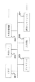
図1は、この実施の形態におけるCTOシステムを示した機器構成図である。このCTOシステムは、ユーザが自ら複数の機能資源を選択してそのユーザ独自にカスタマイズされた製品やサービスの提供を受けられるようにするためのものであって、機能資源を仮想空間内で機能オブジェクトとして表象する複数のオブジェクト表象装置P1と、センタコンピュータP2とを互いにインターネット等の通信網を介して双方向通信可能に接続してなるものである。
【0031】
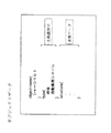
前記オブジェクト表象装置P1は、ユーザが用いるものであり、例えばブラウズ機能を有した汎用コンピュータである。このものは図2に示すように、CPU101、内部メモリ102、HDD等の外部記憶装置103、通信ネットワークに接続するためのモデム等の通信インタフェース104、ディスプレイ105、マウスやキーボードといった入力手段106等を具備する。
【0032】
前記センタコンピュータP2は、例えばサーバ機能を有した汎用コンピュータであり、図3に示すように、CPU201、内部メモリ202、HDD等の外部記憶装置203、通信ネットワークに接続するためのモデム等の通信インタフェース204、ディスプレイ205、マウスやキーボードといった入力手段206等を有する。
【0033】
しかして本実施形態では、図4に示すように、前記オブジェクト表象装置P1のブラウザに例えばプラグインという形で所定のプログラムをインストールし、そのプログラムに基づいてCPU101や周辺機器を共働させることにより、このオブジェクト表象装置P1が、オブジェクトデータ格納部D11、入力受付部11、オブジェクトデータ送受信部12、自動編集部13、制御部14、記録部15、記録データ格納部16、記録データ送信部17、受注手配部18として機能するようにしている。
【0034】
一方、前記センタコンピュータP2には、所定のプログラムをインストールし、そのプログラムに基づいてCPU201や周辺機器を共働させることにより、このセンタコンピュータP2が、オブジェクトデータ送受信部21、オブジェクトデータ格納部D21、記録データ受信部22、指標データ算出部23等としての機能を発揮するように構成している。
【0035】
各部を詳述する。
【0036】
前記オブジェクト表象装置P1において、オブジェクトデータ格納部D11は、複数のオブジェクトデータを格納しているものである。このオブジェクトデータは、図5に示すように、当該機能オブジェクトを識別するためのオブジェクト識別子と、機能資源を仮想空間内で機能オブジェクトとして表象するための表象データと、当該機能オブジェクトの役割等を示す名称識別子と、制御対象となる自己又は他の機能オブジェクトの機能を所定イベントの発生を契機として惹起し又は生成するための1又は複数の制御データと、前記各制御データに内的又は外的に関連付けられた第2の名称識別子(制御対象名称識別子)及びイベント識別子とを備えたものである。なお、機能オブジェクトには、例えば図9に示すように、前記表象データと名称識別子のみを有し、自らはなんら働きかけを行わない種類のものもある。また、後述する全ての機能オブジェクトは3次元立体形状をなすものであるが、平面的なものであってもよいのはもちろんである。
【0037】
前記表象データは、例えば機能オブジェクトたる図6に示すサスペンションオブジェクト30においては、各パーツオブジェクト31、32、33…の外形データや、各パーツオブジェクト31、32、33、34…を動き可能とする構造体を示す構造データ、あるいは必要に応じて模様、色彩等を示す表面データ等からなるもので、さらにその構造データ等に応じて予め分類されたサスペンションオブジェクト30に割り付けられた役割を示す名称識別子を内的又は外的に関連付けてある。なお、この表象データは3次元計測器や3次元形状を作成可能なCG、CAD等を利用して得ることができる。すなわち、前記構造データは、各パーツオブジェクト31、32、33、34…をジョイントを介してリンクした構造を示すようにしたものである。ジョイントは、図16に模式的に示すように、前記仮想空間内における相対的若しくは絶対的な位置を示し得るよう基点座標、主軸方向ベクトル成分、ハンドル方向ベクトル成分のセットとして記述されるもので、基本的に主軸ベクトル、ハンドルベクトルの「有/無」とその属性定義により、種々の自由度で記述できるようにしてある。そしてこのジョイントを介して、各パーツオブジェクト31、32、33、34…は互いに自由度を定義されて連結されている。例えば前記サスペンションオブジェクト30において、ロッドパールオブジェクト34は、シリンダパーツオブジェクト32に一方向にスライド移動可能な自由度を有するように、その間のジョイント(図示しない)により連結されている。ところで、各オブジェクト群の連結は、マウスを利用したドラッグ&ドロップで指定したり、マウスでピックしたオブジェクト群として指定する、又、リストから選択する等の方法を採ることができる。そして、本実施形態では、仮想空間内において連結し得る複数のジョイントをそれぞれに設けた一の機能オブジェクトと他の機能オブジェクトとを仮想空間内で連結させる際に、そのオブジェクト内にジョイントが複数ある場合には、一の機能オブジェクトのジョイントと最も近い結合指示された複数のオブジェクト群の相対空間的指定結合条件において、他の機能オブジェクトのジョイントと連結するように構成している。また、このような場合における連結方法は、上述のような条件に限らず、優先度の高いジョイントを利用するなど、他の条件によって連結されるようにしても構わない。一方、前記外形データは、前記構造体を規定する3次元ローカル座標系の所要位置に設定した曲線や曲面を示すポリゴンデータ等であり、前記表面データはその面にテクスチャーマッピング等で貼り付けられる模様や色彩を示すものである。なお、このオブジェクトデータの構成は上述のものに限られるものではなく、他に種々の構成が可能である。
【0038】
名称識別子は、前記機能オブジェクトに割り付けられた役割の上位概念の機能を示すものである。前記サスペンションオブジェクト30に関して言えば、図8に示すように、このものは名称識別子を複数(4つ)有し、それらは上位概念と下位概念との関係にあって階層構造をなす。その他、名称識別子が単独でも構わないし、例えば当該機能オブジェクトが複数の機能を奏し得るようなものであれば機能オブジェクトに並列的に名称識別子が複数定めてあってもよい。
【0039】
制御データは、前記表象データからは独立して追加、削除又は変更可能なものであり、所定イベント特定データの受付を契機として制御対象となる自己又は他の機能オブジェクトの機能を惹起し又は生成するためのものである。具体的には、図9に示すように、上位階層に属する上位単位制御データに対し下位階層に属する下位単位制御データを1又は複数関連付けて階層構造化した複数の単位制御データの組み合わせからなる構造をなす。なお、以下この制御データの説明と同時に、前記第2の名称識別子(制御対象名称識別子)、イベント識別子をも説明する。
【0040】
本実施形態では前記階層は3階層であり最上位階層であるコントロール階層には、前記オブジェクトの動きプロセス、例えば工程を示す上位単位制御データであるコントロールブレードを、各オブジェクトを識別するためのオブジェクト識別子に関連付けて1又は複数属させている。
【0041】
中間階層であるビヘイビア階層には、前記オブジェクトの動きプロセスをさらに詳細に分割した動き規範に関する中位単位制御データであるビヘイビアブレードを各コントロールブレードに関連付けて1又は複数属させている。
【0042】
最下位階層であるアクション階層には、前記オブジェクトの動き規範に関し、より具体的かつ物理的な動きを示す下位単位制御データであるアクションブレードを前記各ビヘイビアブレードに関連付けて1又は複数属させてある。
【0043】
第2の名称識別子は、この制御データの制御対象となる機能オブジェクトに関する役割の上位概念の機能を示すもので、本実施形態では当該制御データに内的に付帯させてある。しかしてその内容に関しては前記名称識別子と同様であるので省略する。
【0044】
イベント識別子は、この制御データが駆動されるイベント条件を示すもので、本実施形態では当該制御データに内的に付帯させてある。
【0045】
一例を挙げて説明する。サスペンションオブジェクト30における前記コントロールブレードは、例えば図8に示すように、ブレード名と、関連付けられるべきビヘイビアブレードのインデックス(パス指定、URL指定等を含む場合もある)と、前記イベント識別子と、このコントロールブレードによる制御対象オブジェクトの名称識別子とを遂にして記述できるようにしたものである。この例におけるイベント識別子は”クリック”であり、ビヘイビアインデックスは、”振動”である。そしてかかるビヘイビアブレードインデックス(下位単位制御データインデックス)がコントロールブレード(上位単位制御インデックス)の内容となる。なお、ビヘイビアインデックスを複数組み合わせて記述することもできるし、イベント識別子とビヘイビアインデックスとの対を複数記載することもできる。
【0046】
また”振動”インデックスを有するビヘイビアブレードには、例えば同図に示すように、関連付けられるべきアクションブレードのインデックス(パス指定、URL指定等を含む場合もある)が示してある。この例におけるアクションインデックスは、”上動”、”下動”の2つであるが3以上でもよいし、1つでも構わない。そしてこれら複数のアクションブレードインデックスの組合せが当該ビヘイビアブレードの内容を示すものとなる。
【0047】
アクションブレードは、例えばオブジェクトの動き内容や形態変化内容を示すものである。ここで動きとは、オブジェクトを構成する各パーツオブジェクトあるいはそれらの集合の位置変化及び姿勢変化を言い、形態変化とは、各パーツオブジェクトの外形データやテクスチャーの変化、すなわち形状や色彩あるいは模様の変化であって前記動きを含まないものを言う。なお本実施形態においては、動き内容と形態変化内容とを区別して記載しているが、これらを区別しないようにしてもよい。より具体的に説明すると、例えば、図10に示すように、動きであることを示す識別子(例えばMOVE)に続けて、必要に応じて動かすべき対象たるオブジェクトの動き内容を示す動きインデックスと、その動きをするための時間を示す時間データとを対にして記述することとしている。これらは複数あっても構わない。動きインデックスには、前記制御対象オブジェクトの姿勢変化や位置変化等を記載する。具体的な記載方法は適宣定めればよく、所定地点への移動や回転を指定できるようにしてもよいし、方向と移動距離を指定したり、方向と回転角度を指定したりできるようにしてもよい。その他に、例えば各種方程式で定義される曲線とその曲線に沿った移動距離とを指定できるようにしたり、また変数や上述した各指定方法を組み合わせたりすることができるようにしてもよい。さらに時間データには、開始時刻と終了時刻を記載するようにしてもよい。
【0048】
なお、同図中、各単位制御データ(ブレード)をこのオブジェクトデータに一体に含める必要はなく、例えばインデックス、URL、パス名等を指定するなどして、別体に存在するようにしても構わない。また、これら各ブレードのインデックスは、前記各パーツオブジェクトの動き又は形態変化を理解可能にテキスト形式で記述してなるものである。
【0049】
さらに、本実施形態ではこれら各ブレードにコンピュータに並行処理と順次処理とのいずれを行うかを認識させるための処理手順識別情報を含ませ得るようにしてある。例えば前述した各ブレードインデックスを、PARARELLEという処理手順識別情報で括ることにより、同時に処理が行われるようにしている。また順次処理を指定する場合は、SEQUENCEという処理手順識別情報で括るか又は単に併記することにより、その記述順に処理が行われるようにしている。なお、処理手順識別情報は、PARARELLE やSEQUENCEに限られず、繰り返しを意味するREPEATやランダム処理を意味するRANDOM等の他、待ち時間を指定するWAIT等、種々のものを単独であるいは組み合わせて使用できるようにもしている。
【0050】
オブジェクトデータ送受信部12は、前記オブジェクトデータを他の機能オブジェクト表象装置P1又はセンタコンピュータP2との間で送受信するものである。送受信される対象は、オブジェクトデータ全体又はその一部、例えば制御データのみ、単位制御データのみ、表象データのみの他、制御データや表象データをそれぞれ独立に変更、削除、追加するための後述するデータ操作用データを含む。
【0051】
入力受付部11は、ユーザによる複数の前記機能オブジェクトの選択入力を受け付けるものである。具体的には、図示しないがプルダウンメニュ等から選択してもよいし、仮想空間内に機能オブジェクトを複数表示し、これらのうちから所望のものをマウスでクリックするなどして選択できるようにしても構わない。またこの入力受付部11は、ユーザによる機能オブジェクトの修正選択入力を受け付ける他、ユーザによる機能オブジェクトの選択決定入力をも受け付けるものである。
【0052】
自動編集部13は、前記入力受付部11で受け付けた複数の機能オブジェクトのうち、組み合わせが不可能なものを抽出し、抽出した機能オブジェクトに代替する機能オブジェクトを設定するものである。具体的に本実施形態では、前記名称識別子及び第2の名称識別子を比較することにより、入力受付部11で受け付けた複数の機能オブジェクトのうち、組み合わせが不可能なものを抽出し、抽出した機能オブジェクトに代替する機能オブジェクトを設定するようにしている。また、本実施形態において、この自動編集部13に、仮想空間内における複数の機能オブジェクトが所定関係にあると判断した際に、その所定関係にある複数の機能オブジェクトを前記ジョイントを利用して結合させる機能を有するように構成している。具体的には、マウスを利用したドラッグ&ドロップで指定したり、マウスでピックしたオブジェクト群として指定する、又、リストから選択する等の方法により、ある仮想空間内で一の機能オブジェクトを選択した際に、その一の機能オブジェクトのジョイントと結合し得るジョイントを有する他の機能オブジェクトがその仮想空間内に複数個あった場合、複数の他の機能オブジェクトのうち、最も一の機能オブジェクトのジョイントに近いジョイントを有する他の機能オブジェクトと、一の機能オブジェクトとが連結されるように構成している。もちろん、その他に例えば、各機能オブジェクトに含まれる前記ジョイントを検索し、互いに結合しあうジョイントがない場合に組み合わせが不可能と判断するようにしてもよい。
【0053】
制御部14は、前記入力受付部11及び自動編集部13で定められた各機能オブジェクトの制御データを解釈実行し、それら機能オブジェクトを組み合わせた場合の機能を前記仮想空間で発揮させるものであり、本実施形態では、一の機能オブジェクトに対し所定の組み合わせ関係にある機能オブジェクトを抽出し、その抽出した機能オブジェクトに係る名称識別子と前記一の機能オブジェクトに係る第2の名称識別子とが所定条件を満たす場合には当該一の機能オブジェクトの制御データを解釈し、その解釈に基づいて前記抽出した機能オブジェクトを直接的又は間接的に制御してその機能を発揮させるものである。
【0054】
ここで前記「所定条件を満たす」とは、本実施形態では複数の名称識別子のうちのいずれかが一致する場合のことである。また前記「所定組み合わせ関係」とは、本実施形態では、前記機能オブジェクト同士の空間的な位置関係のことをいう。
【0055】
具体的にこの制御部14は、図11に示すように、取得した制御データに含まれる処理手順識別情報から、最下層のブレード(本実施形態では下位単位制御データたるアクションブレード)を並行処理すべきものと順次処理すべきものとに解釈分類し、並行処理すべきものは別々の命令キューに、また順次処理すべきものはその処理順にしたがって同一の命令キューに蓄積するリアクタインタプリタとしての役割を担う。命令キューとは、前記内部メモリ102、外部記憶装置103等の所定領域に一時的に又は静的に設定されるものである。
【0056】
その後、前記命令キューに格納されたブレードをローダを介して取り込むリアクタとしての役割をも担う。このリアクタは、同じ命令キューに格納されている単位制御データに関しては先頭順に取り込んで、その時間情報に基づいた動き又は形状変化を生成し、異なった命令キューに格納されているブレードはそれぞれ独立して取り込むものである。
【0057】
このリアクタは、例えば0.1秒などの単位時間毎に1回の処理を行うものであり、取り込んだブレードに含まれる時間情報(時間データ)に基づいて、そのブレードを単位時間での動き又は形状変化を惹起しあるいは生成する時分割変化制御データに分割する。例えば2秒の時間情報を有しているブレードであれば20の時分割変化制御データに分割し、3秒の時間情報を有しているブレードであれば30の時分割変化制御データに分割する。そして、各ブレードに含まれる対象インデックスに基づいて、前記オブジェクトデータから動かすべき又は形状を変化させるべき対象を特定し、前記時分割変化制御データを順次実行することにより、オブジェクトの動き又は形状変化を惹起しあるいは生成する。なお、動き又は形状変化の生成は、最初の時分割変化制御データに単位量を順次足し合わせていくようにしてもよいし、最初の位置を常に基準にして徐々に大きな動き又は形状変化量を与えるようにしてもよい。またそのためにオブジェクトデータに図示しないが現在の状態(位置、姿勢等)を示す現在状態データを生成するようにしている。
【0058】
このとき、互いに異なった命令キューに格納されている複数の単位制御データから生成された時分割変化制御データが存在する場合には、それらを前記単位時間毎の処理で同時に並行して実行し、複数の動き又は形状変化を並行して惹起しあるいは生成する。例えば、図12に示すように、複数のブレードA〜Dが並列に存在する場合に、WAIT等の識別子から決定される処理開始時間の違いや、各ブレードの所要時間の違いから、一部においては複数の動き又は形状変化処理が並行して営まれるとともに、一部においては単独の動き又は形状変化処理が営まれることとなる。
【0059】
さらに本実施形態では、この制御部14が、オブジェクトデータに含まれる制御データの追加、変更又は削除を、前記表象データから独立して行うとともに、前記各ブレードの追加、変更又は削除を他のブレードから独立して行うようにしてある。すなわち、図13に示すように、制御データと形式上同様のものであるが、ビヘイビアブレード等を含まないデータ操作用データ(ブレード操作用データ)が設けてある。このブレード操作用データは、オブジェクト識別子に関連付けられてなるもので、イベント識別子と各ブレード毎の追加、変更又は削除処理を示すデータとを対にして含む。しかして検出されたイベントに合致するイベント識別子を有したものがこのブレード操作用データである場合には、その内容にしたがって前記制御部18が、該当する制御データにおけるブレードの追加、変更又は削除処理を行うようにしている。具体的には、例えばADDが付記されている場合には指定されたブレードの追加が行われ、DELが付記されている場合には、指定されたブレードの削除が行われるようにしてある。また変更の場合は、ADDとDELとを組み合わせて対応するようにしている。そして、この構成により、制御データ及び各ブレードを互いにかつ前記表象データから独立して追加、変更又は削除処理可能にしている。
【0060】
記録部15は、前記入力受付部11で受け付けるユーザによる機能オブジェクトの選択入力等の操作履歴、前記自動編集部13で設定される機能オブジェクトの履歴及び前記制御部14により前記仮想空間内において機能オブジェクトの機能が発揮されることにより生じた現象を、前記内部メモリ202や前記外部記憶装置203の所定領域に形成した記録データ格納部16に記録するものである。
【0061】
記録データ送信部17は、前記記録データ格納部16に格納している記録データを前記センタコンピュータP2に送信するものであって、前記通信インタフェース104等を利用して形成している。
【0062】
受注手配部18は、前記入力受付部11で受け付けた選択決定入力により受け付けられた機能オブジェクトに対応する機能資源の受注手配出力を、前記センタコンピュータP2に行うものであって、前記通信インタフェース104等を利用して形成している。なお、通信インタフェース104を利用せず図示しないプリンタに出力し、しかるのち、機能資源の受注手配を行うといった実施態様であってもよい。また、受注手配先は、前記センタコンピュータP2に限らず、然るべき手配先であってもよい。
【0063】
一方、前記センタコンピュータP2におけるオブジェクトデータ送受信部21は、オブジェクトデータ等を各機能オブジェクト表象装置P1との間で送受信するものある。
【0064】
オブジェクトデータ格納部D21は、前記オブジェクトデータを格納するものである。
【0065】
記録データ受信部22は、前記各機能オブジェクト表象装置P1から送信される記録データを受信するものであって、前記通信インタフェース204等を利用して形成している。
【0066】
指標データ算出部23は、前記記録データ受信部22で受信する記録データに基づき、当該装置を操作するユーザの効率を図る指標を算出するものである。より具体的には、例えば、前記記録データが示す内容が、クリアボタンが押されるといった操作が頻繁に生じていることを示すものであれば、その前の操作が、ユーザにとって「めんどくさい」、「躊躇している」、「難しい」若しくは「間違えている」といった確率が高いことが予想される。このような操作履歴が有する潜在的なパターン等をデータマイニング等により求めることにより、該指標データ算出部23が、装置の使い易さやわかり易さ等を示す指標たるユーザビリティを算出するように構成している。なお、このユーザビリティは、例えば、10段階に設定し、ユーザビリティが最も高ければ10、最も低ければ1を出力するように構成するなど、実施態様に応じて適宜設定することができる。また、算出する指標は、ユーザビリティに限らず、例えば、前記記録データが、一定期間内の利用頻度や利用合計時間等、当該装置の利用に関するデータであれば、マーケティングに応用可能な指標を算出することもできる。
【0067】
このようにして指標データ算出部23は、前記記録データ受信部22で受信する記録データに基づき、全体システムの機能理解及び製品の特徴理解を円滑に行い得る検討をつけるための目印となり、人あるいは当該装置が、全体システム又は製品の評価を好適に行うことができる指標を算出する。
【0068】
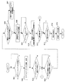
このような構成の本CTOシステムの動作例を、図14を参照しつつ以下に詳述する。
【0069】
この例においては、ユーザによる自動車のカスタマイズ、特にサスペンションのカスタマイズの一例を挙げる。
【0070】
まずユーザが自動車を購買すべく、自動車会社の運営するサイト(センタコンピュータP2)にアクセスしたとする。この結果、ユーザの用いる機能オブジェクト表象装置P1に、仮想空間を表示するための仮想空間データ及び自動車の各パーツオブジェクト(機能オブジェクト)がセンタコンピュータP2のオブジェクトデータ送受信部21等から送信される。これをオブジェクト表象装置P1側のオブジェクトデータ送受信部12が受信し(ステップS01)、オブジェクトデータ格納部D11に格納する。このことにより、例えば図7に示すように、シャーシオブジェクト50と複数のサスペンションオブジェクト30が表示される(ステップS02)。
【0071】
ユーザは、複数のサスペンションオブジェクト30のうちから好みのサスペンションオブジェクト30を選択すべくマウス等によるピッキング操作を行うと、入力受付部11は、当該サスペンションオブジェクト(例えば硬いサスペンションA)が選択されたと判断し、これを受け付ける(ステップS03)。
【0072】
その後、ユーザがドラッグ操作等によりサスペンションオブジェクト30をシャーシオブジェクト50の所定位置に移動させると(ステップS04)、まず自動編集部が、サスペンションオブジェクト30に係る第2の名称識別子とシャーシオブジェクト50の名称識別子とを比較し、選択されたサスペンションオブジェクト30がシャーシオブジェクト50に組み合わせ可能なものか否かを判断する(ステップS05)。組み合わせ可能と判断した場合には、各機能オブジェクトのジョイント同士を連結し(ステップS06)、そうでない場合には、その旨を表示するとともに取り付け可能な別のサスペンションオブジェクト30を自動選定し(ステップS07)、各機能オブジェクトのジョイント同士を連結する(ステップS06)。
【0073】
次にこのようにユーザの選択した、又はそれに代替するサスペンションオブジェクト30が仮決定されると、次にユーザのクリック動作(イベント)の発生を待って(ステップS08)、制御部14がサスペンションオブジェクト30の制御データを解釈し、その制御対象たるシャーシオブジェクト50を制御する(ステップS09)。
【0074】
この場合であればシャーシオブジェクト50は、図7に示すように、上下に振動しサスペンションオブジェクトによる振動効果をユーザは視覚的に確認できることとなる。また、別のサスペンションオブジェクトを取り付けることにより、そのサスペンションオブジェクトによる振動効果も直ちに確認できる。
【0075】
なお、振動させる際にはサスペンションオブジェクト30の変形も必要である。そのためにこのサスペンションオブジェクト30は、図示しないが自身を変形させてその機能を発揮させるための、自身を制御対象に指定してなる機能制御データをさらに有している。
【0076】
一方、ユーザが前記各機能オブジェクトの選択をやり直すべく、修正選択操作を行うと、入力受付部11がこれを受け付け(ステップS10)、前記同様の手順を経て、選択された機能オブジェクトの組み合わせによる作用効果が惹起される。
【0077】
この後、ユーザが機能オブジェクトの選択決定入力を、画面に適宣表示させた入力欄あるいは所定の操作により行うと、入力受付部11がその決定入力を受け付ける(ステップS11)。そして、受注手配部18がその選択決定入力により受け付けられた機能オブジェクトに対応する機能資源の受注手配出力(ステップS12)を行う。
【0078】
また、本実施形態では、ステップS12を終えた際に、上述のステップS03〜ステップS12における操作履歴を記録した記録データをセンタコンピュータP2に送信する(ステップS13)ように構成している。
【0079】
次に、センタコンピュータP2における動作を、図15に示すフロー図を用いて説明する。
【0080】
まず、ユーザが自動車を購買すべく、本サイト(該センタコンピュータP2)にアクセスがあれば(ステップT01)、オブジェクトデータ送受信部21が、オブジェクト格納部D21に格納しているオブジェクトデータをオブジェクト表象装置P1に送信する(ステップT02)。また、前記オブジェクト表象装置P1から記録データを受信すると(ステップT03)、この記録データに基づき、指標データ算出部23が、全体システムの機能理解及び製品の特徴理解を円滑に行うことができるような指標を算出する(ステップT04)。
【0081】
このように、本実施形態によれば、CTOにおける特徴、すなわち、ユーザの多様化する需要にきめ細やかに対応できる特徴に加え、それらの組み合わせによる作用を仮想空間でリアルタイムで実現できるので、従来ユーザにとって把握しにくかった製品の特徴機能が容易にしかも直感的に理解できることとなる。また、自動編集部13による自動編集機能により、ユーザの不適切な選択にも自動的に対応できる。
【0082】
一方、CTOの運営者側にとってみれば、各機能オブジェクトに所定の組み合わせ関係になった他の機能オブジェクトを制御する制御データを埋め込む構成としているので、独立に定義開発した機能オブジェクトのみを用意しておけば、仮想空間内で各機能オブジェクトが自律的かつインタラクティブに動作するため、従来のように組み合わせ毎にいちいちプログラムを作成する必要もなく、新製品や機能変更等にも柔軟に対応できる。特に本実施形態では、機能オブジェクトに含まれる制御データ、単位制御データ、表象データをそれぞれ互いに独立して追加、削除、変更することができるので、その効果が顕著なものとなる。
【0083】
なお、本発明は前記実施形態に限られず、種々の変更が可能である。
【0084】
例えば、前記実施形態において自動編集部は、組み合わせ不可能な機能オブジェクトを抽出しその機能オブジェクトを他のものに変更していたが、前記入力受付部で選択された複数の機能オブジェクトのうち、一の機能オブジェクトの制御データに基づいて他の機能オブジェクトの形態を変化させ、前記他の機能オブジェクトに代替する機能オブジェクトを設定するようにしても構わない。
【0085】
具体的に、アームクレーンにおいてアーム先端部に取り付けているアタッチメントを交換した場合を例にとって説明する。現実にはクラッシャを取り付けるには強度上の問題からアームをも太いものに変えなければならない。しかしてこのことを仮想空間上で行う場合、バケットオブジェクトBK、クラッシャオブジェクトCRの機能制御データに、取り付けられる相手側のアームオブジェクトAMの形態を制御させるようにしておけばよい。すなわち、図17に示すように、当初バケットオブジェクトBKをアームオブジェクトAMに取り付けている場合には、そのバケットオブジェクトBKの機能制御データによってアームオブジェクトAMの形態が規定され、クラッシャオブジェクトCRに取り替えた場合には、図18に示すように、その機能制御データによってアームオブジェクトAMが太くなるように構成することができる。
【0086】
また、選択されたどの機能オブジェクトを優先的に残すかによって、組み合わせ不可能な機能オブジェクトは変動する。これに対応するには、優先する機能オブジェクトの設定を受け付ける優先機能オブジェクト設定部を設けることが好ましい。優先する機能オブジェクトの設定は、ユーザの入力を受け付けるようにしてもよいし、必須の機能オブジェクトが定まっているものであれば、その必須オブジェクトを始点として自動的に設定するようにしてもよい。
【0087】
さらに、このオブジェクト表象装置は、通信網に接続されず、単独に存在するものでも構わない。
【0088】
また、本実施形態では、自動編集部13が、結合する関係にある機能オブジェクト同士を連結させるように構成していたが、例えば、ある仮想空間内で一の機能オブジェクトが選択された際に、その一の機能オブジェクトが、その仮想空間内にある他の全ての機能オブジェクトに対してその一の機能オブジェクト自身が有する制御対象名称識別子を送信し、この制御対象名称識別子によって駆動される他の機能オブジェクトが、そのコントロールブレード等に記述される制御データに基づき、自身若しくは一の機能オブジェクトを動作させ連結を行わせるといった実施態様も考えられる。
【0089】
なお、本実施形態では、記録データ受信部22及び指標データ算出部23をセンタコンピュータP2に設け、このセンタコンピュータP2において、記録データ受信部22で受信した記録データに基づき、指標データ算出部23が装置を操作するユーザの効率を図る指標を算出するように構成していたが、指標データ算出部23を機能オブジェクト表象装置P1に設け、前記指標を算出した後にセンタコンピュータP2に送信するといった実施態様も考えられる。
【0090】
その他、本発明は請求項1に記載された要件が最低必要なものであって、これに加えられる機能等は、その趣旨を逸脱しない範囲において種々変更が可能である。
【0091】
【発明の効果】
以上に詳述したように本発明によれば、CTOのように多数の機能資源の組み合わせにより実現され、かつ各機能資源の選択が可能な製品における特徴、すなわち、ユーザの多様化する需要にきめ細やかに対応できる一方、それらの組み合わせによる作用を仮想空間で実現できるので、ユーザにその製品の特徴機能を把握させることが容易にできる。しかも、各機能オブジェクトに、所定の組み合わせ関係になった他の機能オブジェクトを制御する制御データを埋め込む構成としているので、独立に定義開発した機能オブジェクトのみを用意しておけば、仮想空間内で各機能オブジェクトが自律的かつインタラクティブに動作するため、従来のように組み合わせ毎にいちいちプログラムを作成する必要もなく、また、新製品や機能変更等にも柔軟に対応できる。さらに、ユーザの不適切な選択にも自動的に対応できる。
【0092】
また、機能資源を仮想空間内で機能オブジェクトとして表象するために当該装置を操作した操作履歴及び仮想空間内で実行された現象を記録した記録データに基づき、当該装置を操作するユーザの効率を図る指標を算出すれば、全体システムの機能理解及び製品の特徴理解を円滑に行うことができる。例えば、全体システムを運用して、これを容易に評価することができる。また、ユーザの興味や嗜好等を好適に評価することができるとともに、使い易さやわかり易さ等を示すユーザビリティによって、機能設計に問題があるか否かも評価可能となる。
【図面の簡単な説明】
【図1】本発明の実施形態における全体機器構成図。
【図2】同実施形態における機能オブジェクト表象装置の内部機器構成図。
【図3】同実施形態におけるセンタコンピュータの内部機器構成図。
【図4】同実施形態におけるシステムの全体機能構成を示す機能ブロック図。
【図5】同実施形態におけるオブジェクトデータ構造を示すデータ構造図。
【図6】同実施形態における機能オブジェクトを示すオブジェクト図。
【図7】同実施形態における機能オブジェクトを示すオブジェクト図。
【図8】同実施形態におけるオブジェクトデータの一例を示すデータ説明図。
【図9】同実施形態におけるオブジェクトデータの他の例を示すデータ説明図。
【図10】同実施形態における制御データの構造を示すデータ構造図。
【図11】同実施形態における動き等の惹起あるいは生成に係る処理を説明する説明図。
【図12】同実施形態における動き等の惹起あるいは生成の流れを説明する説明図。
【図13】同実施形態におけるブレード操作データの記載例を示すデータ説明図。
【図14】同実施形態における機能オブジェクト表象装置の動作を示すフローチャート。
【図15】同実施形態におけるセンタコンピュータの動作を示すフローチャート。
【図16】同実施形態におけるジョイントを説明するためのジョイント説明図。
【図17】本発明の他の実施形態における機能オブジェクトを示すオブジェクト図。
【図18】同実施形態における機能オブジェクトを示すオブジェクト図。
【符号の説明】
P1・・・機能オブジェクト表象装置
P2・・・センタコンピュータ
D11・・・オブジェクトデータ格納部
11・・・入力受付部
12・・・オブジェクトデータ送受信部
13・・・自動編集部
14・・・制御部
15・・・記録部
17・・・記録データ送信部
18・・・受注手配部
23・・・指標データ算出部[0001]
TECHNICAL FIELD OF THE INVENTION
According to the present invention, in a system that satisfies the specifications of required goods and services using a plurality of functional resources exhibiting a predetermined function, it is preferable to evaluate, for example, a combination of the plurality of functional resources in a virtual space. The present invention relates to a functional object representation device for performing the following.
[0002]
[Prior art]
Conventionally, in order to explain various functions and effects of functional resources that exert various functions by a plurality of combinations, a standard data list of each functional resource is presented or the operation when combined Is shown in a video or the like (for example, see Patent Document 1).
[0003]
Also, recently, it is called a CTO (Customize To Order) which allows a user to select from predetermined parts and optional items, such as a personal computer, and to purchase a customized product unique to the user. Systems are also known.
[0004]
However, a product such as the CTO, which is realized by a combination of a large number of functional resources and in which each functional resource can be selected, can respond to the diversifying demands of users in a detailed manner. It is difficult for the user to understand the characteristic function of the product. That is, even if a standard data list or the like of each functional resource as described above is presented, it is very difficult for the customer to clearly and intuitively grasp various effects and actions due to the combination of the functional resources. .
[0005]
On the other hand, a simple simulation of a large number of combinations of functional resources on a computer would require the development of a simulation program for each combination, which would be enormous and time-consuming. It also depends on sex and development.
[0006]
[Patent Document 1]
JP 2001-195438 A (Page 3-7, FIG. 1)
[0007]
[Problems to be solved by the invention]
Accordingly, the present invention provides a system in which function resources are displayed as function objects in a virtual space. In the system, control data for controlling other function objects having a predetermined combination relationship is embedded in each function object. By preparing only the function objects that have been selected, the function can be dynamically generated simply by combining a plurality of function objects selected by the user, and a great deal of labor and labor is required to grasp them in advance. In order to make the system such as CTO more suitable by making it possible to quickly and dynamically generate and clearly grasp the effect of this kind of combination of functional resources that required is there.
[0008]
[Means for Solving the Problems]
That is, the functional object representation device according to the present invention directly or indirectly changes the function or form of the representation data for representing the functional resources as the functional objects in the virtual space and the other functional objects in a predetermined combination relationship. An object data storage unit in which object data having a structure having control data for causing or generating the object data is stored;
An input receiving unit that receives a selection input of a plurality of the functional objects by a user,
An automatic editing unit for extracting a function object that cannot be combined from among the plurality of function objects received by the input receiving unit, and setting a function object to be substituted for the extracted function object, or performing editing for changing the form thereof. When,
A control unit that interprets and executes control data of each functional object determined by the input receiving unit and the automatic editing unit, and exerts a function when the functional objects are combined in the virtual space. I do.
[0009]
Here, the “virtual space” is an area set to represent a functional object on a display, and is not limited to three-dimensional but includes two-dimensional ones. The “function” is a function or role provided in a certain thing, and the “form” is a shape, a color, a pattern, or a combination thereof. The functions and form changes include those that are represented as form changes that cannot occur in reality. The “functional resource” indicates an object having the above-described function, and includes an imaginary object in addition to an actual object. For example, machines and humans are functional resources.
[0010]
Such a product is realized by a combination of a large number of functional resources such as a CTO, and is capable of selectively responding to diversifying demands of users, that is, a feature of a product in which each functional resource can be selected. Since the effects of these combinations can be realized in a virtual space, it is easy for the user to understand the characteristic functions of the product. In addition, since control data for controlling other function objects having a predetermined combination relationship is embedded in each function object, if only independently defined and developed function objects are prepared, each function object can be created in the virtual space. Since the functional objects operate autonomously and interactively, there is no need to create a program for each combination as in the related art, and it is possible to flexibly cope with a new product, a function change, and the like. Furthermore, it is possible to automatically respond to inappropriate selection by the user.
[0011]
For example, in order to be able to change the function object set by the automatic editing unit or change an input error, the input receiving unit must accept a user's correction selection input of the functional object. Is preferred.
[0012]
In order to be able to make an order immediately upon selection of a functional object, the input receiving unit receives a user's input for selecting a functional object, and corresponds to the functional object received by the selection input. It is desirable that the system further includes an order arranging unit for arranging and outputting the functional resources to be ordered.
[0013]
As a specific mode, the object data between the functional objects further includes a name identifier assigned to the functional object, and a second name identifier of the functional object to be controlled, and the control unit includes: A function object having a predetermined combination relationship with the function object is extracted, and when the name identifier of the extracted function object and the second name identifier of the one function object satisfy a predetermined condition, the one The control data of the functional object is interpreted, and the extracted functional object is directly or indirectly controlled based on the interpretation to exert the function.
[0014]
Here, the “name” indicates the role assigned to the function object, and the name identifier may be simply a “rolling element” if the function is represented by a higher concept, such as a caster. However, it may be more concretely and structurally represented. For example, a “wheel and wheel rotation shaft and mounting plate” may be used.
[0015]
Of course, if the function object has a plurality of roles, a plurality of name identifiers may be included in one object data in parallel. A plurality of name identifiers having a hierarchical structure may be included so as to include from the upper concept to the lower concept.
[0016]
The above “satisfies the predetermined conditions” means that the name identifiers match each other, the name identifiers have a relationship between a superordinate concept and a subordinate concept, and if there are a plurality of name identifiers, any one of them matches. This is the case.
[0017]
Further, the "predetermined combination relationship" refers to a spatial positional relationship between the functional objects, a structural relationship between the functional objects, a role relationship between the functional objects, or a combination thereof. For example, the positional relationship is a relationship in which another functional object is located at a predetermined spatial position with respect to one functional object, or within a certain spatial position range. The structural relationship is a structural relationship that is not affected by the positional relationship, such as the relationship between an outlet and an electric light. Although they do not depend on the positional relationship, they have a structural relationship of being connected by an electric cable, and the electric lamp emits light by being supplied with power from an outlet. The role relationship is a relationship between roles of the function object. For example, when an instruction speaker for giving an instruction in Japanese and a human exist in a virtual space, only a person who has a role of understanding Japanese responds according to the instruction of the instruction speaker. In this way, it refers to the relationship of roles such as "Japanese generation" and "Japanese understanding".
[0018]
In this case, the automatic editing unit compares the name identifier with the second name identifier to extract and extract a plurality of functional objects that cannot be combined from the plurality of functional objects received by the input receiving unit. It is preferable to set a function object to substitute for the function object.
[0019]
Specifically, if the name identifiers match, if the name identifiers are in the relationship between the superordinate concept and the subordinate concept, if there are multiple name identifiers, and if any of them match, etc. It may be determined that the combination is possible, and otherwise, it may be determined that the combination is not possible.
[0020]
As another specific mode of the automatic editing unit, among the plurality of functional objects selected by the input receiving unit, the form of another functional object is changed based on control data of one functional object, and the other A function object that sets a function object to be substituted for the above function object can be cited.
[0021]
If the control data and the representation data belonging to the function object can be added, deleted, or changed independently of each other, the representation data and the function control data are independent of each other, so that the development and the like become easy. In addition, the function control data or the representation data can be independently transmitted and received between the functional object representation devices, and the dynamic change of the object data can be performed without imposing a large load on the communication.
[0022]
Furthermore, if the function control data has a structure including a plurality of unit control data that can be independently added, deleted, or changed, the function control data can be realized by a combination of quantized unit control data. Speeding up of design can be promoted. At this time, it is desirable to transmit and receive data for designating change, deletion, and addition of the control data, the representation data, or the unit control data, and to cause the control unit to interpret and execute the data.
[0023]
As a preferred embodiment from the viewpoint of development, the function control data may be in a text format.
[0024]
By the way, in order to extract a user's behavior and evaluate its characteristics, etc., an operation history of operating the device and a phenomenon executed in the virtual space are recorded in order to represent a functional resource as a functional object in the virtual space. It is desirable to have a recording unit that performs the recording.
[0025]
In addition, such a behavior of the user is, for example, an index for extracting a required function, an option or a function that arouses interest, and an index for an operation provider to watch and apply to marketing. Preferably, the apparatus further includes a recording data transmitting unit that transmits data recorded by the recording unit to the outside, and the device is used to represent functional resources as functional objects in a virtual space. An index data calculation unit that calculates an index for improving the efficiency of the user who operates the device based on the operation history of the operation and the phenomenon executed in the virtual space may be provided. In addition, in order to optimize the layout of the production line in the factory, the layout of office personnel and office equipment, robots and transfer machines that have control data and operate autonomously, and the personnel and office equipment are function objects And the index data calculation unit may be configured to calculate an index for evaluating the efficiency of the configured system based on a history of phenomena in which they are autonomously linked and operated in combination. . Further, if the index is configured to be calculated based on data on the use of the device, such as the frequency of use or the total use time within a certain period, the effect can be remarkable.
[0026]
Here, the "index" is a landmark for making a study that facilitates understanding of the function of the overall system and understanding of the features of the product, as well as the functions required for the product and the options and functions that the market is interested in. And a mark for judging the operational efficiency related to the configuration design of the whole system. In other words, a person or the device can appropriately perform a quantitative and qualitative evaluation of the entire system or the product by using an “index” that can evaluate usability, user behavior (user behavior), and system efficiency.
[0027]
Further, in order to preferably connect the functional objects in the virtual space, the functional object includes a joint described by data that can indicate a relative or absolute position in the virtual space. Wherein the plurality of functional objects in the virtual space are combined by combining joints provided in the respective functional objects, and in particular, the automatic editing unit is configured to perform the plurality of functions in the virtual space. When it is determined that the objects have a predetermined relationship, it is preferable that a plurality of functional objects having the predetermined relationship be combined using the joint.
[0028]
BEST MODE FOR CARRYING OUT THE INVENTION
Hereinafter, embodiments of the present invention will be described.
[0029]
BEST MODE FOR CARRYING OUT THE INVENTION
Hereinafter, embodiments of the present invention will be described.
[0030]
FIG. 1 is a device configuration diagram showing a CTO system in this embodiment. This CTO system is intended to allow a user to select a plurality of functional resources and receive the provision of a product or service customized for the user, and to store the functional resources in a functional object in a virtual space. A plurality of object representation devices P1 and a center computer P2 are connected to each other via a communication network such as the Internet so as to be capable of two-way communication.
[0031]
The object representation device P1 is used by a user, and is, for example, a general-purpose computer having a browse function. As shown in FIG. 2, this includes a
[0032]
The center computer P2 is, for example, a general-purpose computer having a server function, and as shown in FIG. 3, a
[0033]
In the present embodiment, as shown in FIG. 4, a predetermined program is installed in the browser of the object representation device P1 in the form of, for example, a plug-in, and the
[0034]
On the other hand, a predetermined program is installed in the center computer P2, and the
[0035]
Each part will be described in detail.
[0036]
In the object representation device P1, the object data storage section D11 stores a plurality of object data. This object data, as shown in FIG. 5, indicates an object identifier for identifying the function object, representation data for representing the function resource as a function object in the virtual space, a role of the function object, and the like. A name identifier, one or more control data for initiating or generating a function of the self or another function object to be controlled upon occurrence of a predetermined event, and an internal or external It is provided with an associated second name identifier (control target name identifier) and an event identifier. As shown in FIG. 9, for example, some functional objects have only the representative data and the name identifier, and do not act on themselves. In addition, all the functional objects described below have a three-dimensional three-dimensional shape, but may of course be planar.
[0037]
For example, in the case of the
[0038]
The name identifier indicates a function of a higher concept of the role assigned to the function object. As for the
[0039]
The control data can be added, deleted, or changed independently of the representation data, and triggers or generates a function of the self or another functional object to be controlled upon reception of the predetermined event specifying data. It is for. Specifically, as shown in FIG. 9, a structure composed of a combination of a plurality of unit control data hierarchically structured by associating one or more lower unit control data belonging to a lower hierarchy with the upper unit control data belonging to an upper hierarchy. Make The second name identifier (control target name identifier) and the event identifier will be described together with the description of the control data.
[0040]
In this embodiment, the hierarchy is three layers, and the control hierarchy, which is the highest hierarchy, includes a control blade, which is higher unit control data indicating a movement process of the object, for example, a process, an object identifier for identifying each object. And one or more of them.
[0041]
In the behavior hierarchy, which is an intermediate hierarchy, one or a plurality of behavior blades, which are intermediate unit control data relating to a motion rule obtained by further dividing the motion process of the object, are associated with each control blade.
[0042]
In the action hierarchy, which is the lowest hierarchy, one or more action blades, which are lower unit control data indicating more specific and physical movements with respect to the motion norms of the object, are associated with the respective behavior blades. .
[0043]
The second name identifier indicates a function of a higher concept of a role related to a function object to be controlled by the control data, and is internally attached to the control data in the present embodiment. Since the contents are the same as those of the name identifier, the description is omitted.
[0044]
The event identifier indicates an event condition under which the control data is driven. In the present embodiment, the event identifier is internally attached to the control data.
[0045]
An example will be described. As shown in FIG. 8, for example, the control blade in the
[0046]
In the behavior blade having the “vibration” index, for example, as shown in the figure, the index of the action blade to be associated (which may include path designation, URL designation, etc.) is shown. The action index in this example is two of “upward movement” and “downward movement”, but may be three or more, or may be one. Then, the combination of the plurality of action blade indexes indicates the content of the behavior blade.
[0047]
The action blade indicates, for example, the content of movement or the form change of the object. Here, movement refers to a change in the position and orientation of each part object or a set of those constituting the object, and a morphological change refers to a change in external data or texture of each part object, that is, a change in shape, color, or pattern. And does not include the movement. In the present embodiment, the motion content and the form change content are described separately, but these may not be distinguished. More specifically, for example, as shown in FIG. 10, following an identifier (for example, MOVE) indicating a motion, a motion index indicating a motion content of an object to be moved as necessary, The time data indicating the time for the movement is described as a pair. These may be plural. In the motion index, a posture change, a position change, and the like of the control target object are described. The specific description method may be appropriately specified, and it may be possible to specify movement or rotation to a predetermined point, or to specify the direction and movement distance, or the direction and rotation angle. You may. In addition, for example, a curve defined by various equations and a moving distance along the curve may be specified, or a combination of variables and the above-described specifying methods may be used. Furthermore, the start time and the end time may be described in the time data.
[0048]
In the figure, it is not necessary to integrally include each unit control data (blade) in this object data, and the unit control data (blade) may exist separately by designating, for example, an index, a URL, a path name and the like. Absent. The index of each blade is described in a text format so that the movement or change in form of each part object can be understood.
[0049]
Further, in this embodiment, each blade can include processing procedure identification information for causing the computer to recognize whether to perform parallel processing or sequential processing. For example, the above-described blade indexes are grouped by processing procedure identification information called PARALLELE so that the processing is performed simultaneously. In the case where sequential processing is designated, the processing is performed in the order of the description by enclosing it with processing procedure identification information called SEQUENCE or simply adding it together. Note that the processing procedure identification information is not limited to PARARELE or SEQUENCE, and various types of information such as REPEAT for repetition, RANDOM for random processing, and WAIT for specifying a waiting time can be used alone or in combination. I also do.
[0050]
The object data transmitting / receiving
[0051]
The
[0052]
The
[0053]
The control unit 14 interprets and executes control data of each function object determined by the
[0054]
Here, “satisfies the predetermined condition” means that in the present embodiment, any one of the plurality of name identifiers matches. In the present embodiment, the “predetermined combination relationship” refers to a spatial positional relationship between the functional objects.
[0055]
Specifically, as shown in FIG. 11, the control unit 14 should perform the parallel processing of the lowermost blade (the action blade which is the lower unit control data in the present embodiment) from the processing procedure identification information included in the acquired control data. They are interpreted and classified as kimono and those to be processed sequentially, and those to be processed in parallel serve as a reactor interpreter that accumulates in a separate instruction queue and those to be processed sequentially in the same instruction queue according to their processing order. The instruction queue is temporarily or statically set in a predetermined area such as the
[0056]
Thereafter, it also serves as a reactor for taking in the blade stored in the instruction queue via a loader. This reactor fetches the unit control data stored in the same instruction queue in the leading order, generates a motion or shape change based on the time information, and independently stores the blades stored in different instruction queues. It is something to take in.
[0057]
This reactor performs processing once per unit time, for example, 0.1 second. Based on time information (time data) included in the taken-in blade, the reactor moves or moves in a unit time. It is divided into time-division change control data that causes or generates a shape change. For example, a blade having time information of 2 seconds is divided into 20 time-division change control data, and a blade having time information of 3 seconds is divided into 30 time-division change control data. . Then, based on the target index included in each blade, a target to be moved or a shape to be changed is specified from the object data, and the time-division change control data is sequentially executed to determine the movement or the shape change of the object. Trigger or generate. In addition, the generation of the movement or the shape change may be such that the unit amount is sequentially added to the first time-division change control data, or a gradually large movement or the shape change amount is always based on the first position. You may give it. To this end, current state data (not shown) indicating the current state (position, posture, etc.) is generated in the object data.
[0058]
At this time, if there is time-division change control data generated from a plurality of unit control data stored in mutually different instruction queues, these are executed simultaneously in parallel in the processing for each unit time, Initiate or generate multiple movements or shape changes in parallel. For example, as shown in FIG. 12, when a plurality of blades A to D are present in parallel, some of the blades A to D may have a difference in processing start time determined from an identifier such as WAIT or a difference in required time of each blade. In this case, a plurality of motion or shape change processes are performed in parallel, and in some cases, a single motion or shape change process is performed.
[0059]
Further, in the present embodiment, the control unit 14 performs addition, change, or deletion of control data included in object data independently of the representation data, and performs addition, change, or deletion of each blade with another blade. It is done independently from. That is, as shown in FIG. 13, data operation data (blade operation data) which is similar in form to the control data but does not include a behavior blade or the like is provided. The blade operation data is associated with an object identifier, and includes a pair of an event identifier and data indicating addition, change, or deletion processing for each blade. If the data having the event identifier matching the detected event is the blade operation data, the
[0060]
The
[0061]
The recording
[0062]
The
[0063]
On the other hand, the object data transmitting / receiving
[0064]
The object data storage D21 stores the object data.
[0065]
The recording
[0066]
The index
[0067]
In this way, the index
[0068]
An operation example of the present CTO system having such a configuration will be described in detail below with reference to FIG.
[0069]
In this example, an example of customizing a car by a user, particularly customizing a suspension, will be described.
[0070]
First, it is assumed that the user accesses a site (center computer P2) operated by an automobile company to purchase an automobile. As a result, the virtual space data for displaying the virtual space and each part object (functional object) of the vehicle are transmitted from the object data transmitting / receiving
[0071]
When the user performs a picking operation with a mouse or the like to select a
[0072]
Thereafter, when the user moves the
[0073]
Next, when the
[0074]
In this case, the
[0075]
Note that the
[0076]
On the other hand, when the user performs a correction selection operation in order to redo the selection of each of the functional objects, the
[0077]
Thereafter, when the user performs a selection decision input of a functional object by an input field appropriately displayed on the screen or a predetermined operation, the
[0078]
Further, in the present embodiment, when step S12 is completed, the recording data in which the operation history in steps S03 to S12 is recorded is transmitted to the center computer P2 (step S13).
[0079]
Next, the operation of the center computer P2 will be described with reference to the flowchart shown in FIG.
[0080]
First, if the user has access to this site (the center computer P2) to purchase a car (step T01), the object data transmitting / receiving
[0081]
As described above, according to the present embodiment, in addition to the features of the CTO, that is, features that can finely respond to the diversifying demands of users, the effects of the combination thereof can be realized in real time in a virtual space. The user can easily and intuitively understand the characteristic functions of the product that are difficult to grasp. Further, the automatic editing function of the
[0082]
On the other hand, from the point of view of the operator of the CTO, control data for controlling other functional objects having a predetermined combinational relationship is embedded in each functional object, so that only independently defined and developed functional objects are prepared. In this case, since each functional object operates autonomously and interactively in the virtual space, it is not necessary to create a program for each combination as in the related art, and it is possible to flexibly cope with a new product, a function change, and the like. In particular, in the present embodiment, the control data, unit control data, and representation data included in the functional object can be added, deleted, and changed independently of each other, so that the effect is remarkable.
[0083]
Note that the present invention is not limited to the above embodiment, and various modifications are possible.
[0084]
For example, in the above-described embodiment, the automatic editing unit extracts a function object that cannot be combined and changes the function object to another one. However, among the plurality of function objects selected by the input receiving unit, The form of another function object may be changed based on the control data of the function object, and a function object to be substituted for the other function object may be set.
[0085]
Specifically, a case in which the attachment attached to the arm tip in the arm crane is replaced will be described as an example. In reality, in order to install a crusher, it is necessary to change the arm to a thick one due to strength problems. When this is performed in a virtual space, the function control data of the bucket object BK and the crusher object CR may control the form of the attached arm object AM. That is, as shown in FIG. 17, when the bucket object BK is initially attached to the arm object AM, the form of the arm object AM is defined by the function control data of the bucket object BK, and the bucket object BK is replaced with the crusher object CR. In this case, as shown in FIG. 18, the arm object AM can be made thicker by the function control data.
[0086]
The functional objects that cannot be combined change depending on which of the selected functional objects is to be preferentially left. To cope with this, it is preferable to provide a priority function object setting unit that receives a setting of a priority function object. The setting of the function object to be prioritized may be performed by accepting a user's input, or may be automatically set with the essential object as a starting point if the essential function object is determined.
[0087]
Further, the object representation device may be a single device that is not connected to a communication network.
[0088]
Further, in the present embodiment, the
[0089]
In the present embodiment, the recording
[0090]
In addition, the present invention requires at least the requirements described in
[0091]
【The invention's effect】
As described in detail above, according to the present invention, a feature of a product realized by a combination of a large number of functional resources such as a CTO and in which each functional resource can be selected, that is, a demand for diversifying users. While it is possible to respond finely, it is possible to realize the function of the combination in a virtual space, so that it is easy for the user to understand the characteristic function of the product. In addition, since control data for controlling other function objects having a predetermined combination relationship is embedded in each function object, if only independently defined and developed function objects are prepared, each function object can be created in the virtual space. Since the functional objects operate autonomously and interactively, there is no need to create a program for each combination as in the related art, and it is possible to flexibly cope with a new product, a function change, and the like. Furthermore, it is possible to automatically respond to inappropriate selection by the user.
[0092]
Further, the efficiency of the user who operates the device is improved based on the operation history of operating the device and the recorded data that records the phenomenon executed in the virtual space in order to represent the functional resource as a functional object in the virtual space. By calculating the index, it is possible to smoothly understand the functions of the entire system and the features of the product. For example, the entire system can be operated and evaluated easily. In addition, it is possible to appropriately evaluate the user's interests, preferences, and the like, and it is also possible to evaluate whether or not there is a problem in the function design by usability indicating ease of use and understandability.
[Brief description of the drawings]
FIG. 1 is an overall device configuration diagram according to an embodiment of the present invention.
FIG. 2 is an internal device configuration diagram of the functional object representation device according to the embodiment;
FIG. 3 is an internal device configuration diagram of a center computer in the embodiment.
FIG. 4 is a functional block diagram showing the overall functional configuration of the system according to the embodiment;
FIG. 5 is a data structure diagram showing an object data structure in the embodiment.
FIG. 6 is an object diagram showing functional objects in the embodiment.
FIG. 7 is an object diagram showing functional objects in the embodiment.
FIG. 8 is a data explanatory view showing an example of object data in the embodiment.
FIG. 9 is a data explanatory diagram showing another example of the object data in the embodiment.
FIG. 10 is a data structure diagram showing a structure of control data in the embodiment.
FIG. 11 is an explanatory diagram illustrating a process related to inducing or generating a motion or the like in the embodiment.
FIG. 12 is an explanatory diagram illustrating a flow of inducing or generating a motion or the like in the embodiment.
FIG. 13 is a data explanatory diagram showing a description example of blade operation data in the embodiment.
FIG. 14 is an exemplary flowchart showing the operation of the functional object representation device according to the embodiment;
FIG. 15 is an exemplary flowchart showing the operation of the center computer in the embodiment.
FIG. 16 is a joint explanatory diagram for explaining the joint according to the embodiment;
FIG. 17 is an object diagram showing a functional object according to another embodiment of the present invention.
FIG. 18 is an object diagram showing functional objects in the embodiment.
[Explanation of symbols]
P1 ... Functional object representation device
P2: Center computer
D11: Object data storage unit
11 ・ ・ ・ Input reception unit
12 ... object data transmission / reception unit
13: Automatic editing unit
14 ... Control unit
15 Recording unit
17 ・ ・ ・ Recording data transmitting unit
18 ・ ・ ・ Order Arrangement Department
23: Index data calculation unit
Claims (18)
ユーザによる複数の前記機能オブジェクトの選択入力を受け付ける入力受付部と、
前記入力受付部で受け付けた複数の機能オブジェクトのうち、組み合わせが不可能なものがある場合には、その機能オブジェクトに代替する機能オブジェクトを設定し、又はその形態を変化させる自動編集部と、
前記入力受付部及び自動編集部で定められた各機能オブジェクトの制御データを解釈実行し、それら機能オブジェクトを組み合わせた場合の機能を前記仮想空間で発揮させる制御部とを備えている機能オブジェクト表象装置。It has representation data for representing a functional resource as a functional object in a virtual space, and control data for directly or indirectly inducing or generating a function or form change of another functional object in a predetermined combination relationship. An object data storage unit in which object data of the structure is stored;
An input receiving unit that receives a selection input of a plurality of the functional objects by a user,
If a plurality of functional objects received by the input receiving unit are not possible to be combined, an automatic editing unit that sets a functional object to substitute for the functional object or changes its form,
A control unit for interpreting and executing control data of each function object determined by the input receiving unit and the automatic editing unit, and exerting a function when the function objects are combined in the virtual space; .
前記制御部が、一の機能オブジェクトに対し所定の組み合わせ関係にある機能オブジェクトを抽出し、その抽出した機能オブジェクトに係る名称識別子と前記一の機能オブジェクトに係る第2の名称識別子とが所定条件を満たす場合には当該一の機能オブジェクトの制御データを解釈し、その解釈に基づいて前記抽出した機能オブジェクトを直接的又は間接的に制御するものである請求項1乃至3いずれか記載の機能オブジェクト表象装置。The object data further includes a name identifier assigned to the function object, and a second name identifier of the function object to be controlled,
The control unit extracts a function object having a predetermined combination relationship with one function object, and a name identifier of the extracted function object and a second name identifier of the one function object satisfy a predetermined condition. 4. The functional object representation according to claim 1, wherein when satisfied, the control data of the one functional object is interpreted, and the extracted functional object is directly or indirectly controlled based on the interpretation. apparatus.
Priority Applications (1)
| Application Number | Priority Date | Filing Date | Title |
|---|---|---|---|
| JP2002319158A JP2004152196A (en) | 2002-10-31 | 2002-10-31 | Functional object representation device |
Applications Claiming Priority (1)
| Application Number | Priority Date | Filing Date | Title |
|---|---|---|---|
| JP2002319158A JP2004152196A (en) | 2002-10-31 | 2002-10-31 | Functional object representation device |
Publications (1)
| Publication Number | Publication Date |
|---|---|
| JP2004152196A true JP2004152196A (en) | 2004-05-27 |
Family
ID=32462077
Family Applications (1)
| Application Number | Title | Priority Date | Filing Date |
|---|---|---|---|
| JP2002319158A Pending JP2004152196A (en) | 2002-10-31 | 2002-10-31 | Functional object representation device |
Country Status (1)
| Country | Link |
|---|---|
| JP (1) | JP2004152196A (en) |
Cited By (1)
| Publication number | Priority date | Publication date | Assignee | Title |
|---|---|---|---|---|
| US8726126B2 (en) | 2010-03-23 | 2014-05-13 | Apple Inc. | Non-regular parity distribution detection via metadata tag |
-
2002
- 2002-10-31 JP JP2002319158A patent/JP2004152196A/en active Pending
Cited By (2)
| Publication number | Priority date | Publication date | Assignee | Title |
|---|---|---|---|---|
| US8726126B2 (en) | 2010-03-23 | 2014-05-13 | Apple Inc. | Non-regular parity distribution detection via metadata tag |
| US9274887B2 (en) | 2010-03-23 | 2016-03-01 | Apple Inc. | Non-regular parity distribution detection via metadata tag |
Similar Documents
| Publication | Publication Date | Title |
|---|---|---|
| Yew et al. | Towards a griddable distributed manufacturing system with augmented reality interfaces | |
| US8175419B2 (en) | Image search apparatus, image search method, and storage medium storing a program for causing a search apparatus to execute a search method | |
| US8949321B2 (en) | Method for creating image and or text-based projects through an electronic interface from a mobile application | |
| US20130283141A1 (en) | Client Agnostic Spatial Workflow Form Definition and Rendering | |
| US10192022B2 (en) | Geometric modeling system with intelligent behaviors of design components | |
| US20060106682A1 (en) | Web based configuration tool | |
| JP5889009B2 (en) | Document management server, document management method, program | |
| US20130073969A1 (en) | Systems and methods for web based application modeling and generation | |
| Cui et al. | 3D printing in the context of cloud manufacturing | |
| US20220215457A1 (en) | Manufacturing ordering assistance apparatus, method and storage medium | |
| JP4238012B2 (en) | Functional object data, functional object representation system, object data transmission side device, object data reception side device and management device in functional object representation system | |
| Keller et al. | Multiple views to support engineering change management for complex products | |
| JP2009163424A (en) | Information processor, control method, and program | |
| CN114730435A (en) | Management server and product search method | |
| JP2004152196A (en) | Functional object representation device | |
| JP4804263B2 (en) | Product information providing system, product information providing method, and server system | |
| CN104796570B (en) | Communication control method and image formation system in image formation system | |
| JP4633492B2 (en) | Design information management apparatus and design information management method | |
| JP5084702B2 (en) | Analysis data input device, CAE device, analysis data input method, and program | |
| JP2002133264A (en) | Method and device for providing information on commodities | |
| CA2774894A1 (en) | Client agnostic spatial workflow form definition and rendering | |
| KR101575446B1 (en) | Method, system and computer-readable recording medium for enabliing interactions regarding fashion designs | |
| JP5674170B2 (en) | Information processing system, information processing apparatus, information processing method, and program | |
| JP2002259469A (en) | Computer-readable recording medium with cad data managing program recorded thereon and the program | |
| KR101150992B1 (en) | Business Process Management And Management Method Thereof Using multi-touch user interfaces |