JP2004150082A - Retaining stage of roof unit - Google Patents
Retaining stage of roof unit Download PDFInfo
- Publication number
- JP2004150082A JP2004150082A JP2002314943A JP2002314943A JP2004150082A JP 2004150082 A JP2004150082 A JP 2004150082A JP 2002314943 A JP2002314943 A JP 2002314943A JP 2002314943 A JP2002314943 A JP 2002314943A JP 2004150082 A JP2004150082 A JP 2004150082A
- Authority
- JP
- Japan
- Prior art keywords
- roof unit
- roof
- base plate
- holding
- ridge
- Prior art date
- Legal status (The legal status is an assumption and is not a legal conclusion. Google has not performed a legal analysis and makes no representation as to the accuracy of the status listed.)
- Withdrawn
Links
Images


Landscapes
- Conveying And Assembling Of Building Elements In Situ (AREA)
Abstract
Description
【0001】
【発明の属する技術分野】
この発明は、棟を有する屋根ユニットにおいて、その棟と平行な垂直端面を底面として直立保持し、またはその保持状態で屋根ユニットを運搬するための屋根ユニット保持用架台に関する。
【0002】
【従来の技術】
従来から、ユニット住宅等のユニット建物においては、あらかじめ製造工場内で屋根梁・野地板・小屋根パネル等が組み付けられて屋根ユニットとされたものが建築現場に運送され、建築現場において建物上部にその屋根ユニットが組み付けられている。また、外観部材としての屋根パネルも、工場で製造された後に建築現場に運送され、建築現場において屋根ユニットの野地板への組み付けが行われている。
【0003】
例えば、工場でユニット化した屋根をトラックの荷台上に垂直に立てて現場に運び、その荷台から屋根を吊り下げて所望の姿勢まで反転させる方法が考案されている(例えば、特許文献1)。この方法によれば、屋根を寝かせることなく直立させて運搬することができるので、トラックの荷台から屋根がはみ出すこともなく安全に効率よく運搬することができるものとなっている。
【0004】
【特許文献1】
特開昭59−42152号公報
【0005】
【発明が解決しようとする課題】
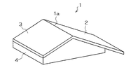
しかしながら、この特許文献1に記載の方法によれば、屋根を直立させた場合にその底面に当たる面が広い面積を有して自立するような場合にはトラックの荷台に載せて建築現場に運ぶことができるが、例えば図12に示すように棟1aから野地板2,3が互いに傾斜して延びるような屋根ユニット1においては、直立させた場合にその底面となる棟と平行な垂直端面(以下、垂直端面と略す。)4の面積が小さいために自立することができず、この垂直端面4を底面として直立させて荷台に載せることができないという問題がある。
【0006】
例え何らかの支持手段によってこの屋根ユニット1を支持したとしても、底面としての垂直端面4の面積が小さいので直立させた場合に不安定となってしまい、トラックの荷台に載せて運搬するような場合は、揺れて転倒することも考えられる。
【0007】
本発明は上記の事情に鑑みて為されたもので、棟と平行な垂直端面の面積が小さい屋根ユニットであっても、転倒することなく確実にその垂直端面を底面として屋根ユニットを直立させて保持することができる屋根ユニット保持用架台を提供することを課題とする。
【0008】
【課題を解決するための手段】
上記の課題を解決するために、本発明の請求項1に記載の屋根ユニット保持用架台は、棟とその棟から互いに傾斜して延びる野地板とを有する屋根ユニットの棟と平行な垂直端面を底面として屋根ユニットを直立保持するための屋根ユニット保持用架台であって、棟と平行な垂直端面に係合する係合部と、野地板の傾斜に沿ってその野地板を支持するための野地板支持枠とを有することを特徴とする。
【0009】
請求項2に記載の屋根ユニット保持用架台は、請求項1に記載の屋根ユニット保持用架台において、係合部が棟と平行な垂直端面に形成された係合孔に係合する係合ピンであることを特徴とする。
【0010】
請求項3に記載の屋根ユニット保持用架台は、請求項1又は請求項2のうちいずれかに記載の屋根ユニット保持用架台において、平板状の屋根パネルの板面が屋根ユニットの野地板の板面と平行となるように屋根パネルを支持可能であることを特徴とする。
【0011】
請求項4に記載の屋根ユニット保持用架台は、請求項1から請求項3のうちいずれか1項に記載の屋根ユニット保持用架台において、屋根ユニットの野地板に固定されて野地板を支持する支持部材が野地板支持枠に収納可能に設けられていることを特徴とする。
【0012】
請求項5に記載の屋根ユニット保持用架台は、請求項4に記載の屋根ユニット保持用架台において、支持部材の一端部が野地板支持枠に枢着され、回動可能に収納可能であることを特徴とする。
【0013】
【発明の実施の形態】
以下、本発明の実施の形態を図面に基づいて説明する。
【0014】
図1(a)〜図1(c)は、本発明の実施の形態に係る屋根ユニット保持用架台5の3面図であり、図2はその外観斜視図である。この実施の形態においては、屋根ユニット保持用架台5は、鉄・アルミ等の金属を材料とする断面四角形の柱状部材が骨組みされて構成されている。
【0015】
もちろん屋根ユニット保持用架台を構成する柱状部材としては、金属材料に限られず、木材等であってもよい。また、柱状部材の断面も四角形に限る必要はなく、円断面・楕円断面の柱状部材を用いてもよい。柱状部材を用いるものでなく、板状パネルを用いて屋根ユニット保持用架台を構成してももちろんよい。
【0016】
この屋根ユニット保持用架台5は、底面部6、野地板支持枠7、補助枠8a,8b、係合部としての係合ピン9a,9bで大略構成されている。
【0017】
底面部6は、屋根ユニット11(図4参照)や屋根パネル15(図7参照)を載置するためのもので、その上面には野地板支持枠7、補助枠8a,8b、係合ピン9a,9bが固定されている。また、後述するように、この屋根ユニット保持用架台5を運送用トラックの荷台に吊り下げて載せる際に用いるワイヤロープを連結するためのフック10が周囲に設けられている。さらに、運送用トラックに荷台に積み上げた際、その荷台に設けられた複数のピンと係合する位置に図示しない係合孔が形成されている。
【0018】
野地板支持枠7は、底面部6の中央部で図1(b)中やや右寄りに固定されている。屋根ユニット11の野地板12を支持するための傾斜部7aと,屋根パネル15を支持するための傾斜部7bとを有して、側方から見た場合に略三角形状を呈している。
【0019】
傾斜部7bの上部には図1(a)中左右2カ所に支持部材16が設けられている。この支持部材16は、傾斜部7aで支持されない方の野地板13を支持するためのもので、一端部16aで野地板支持枠7の傾斜部7bに枢着されている。屋根ユニット11の野地板13の支持のために使用するときには、図1(b)に示すように傾斜部7bから突出するようにして屋根ユニット11の野地板13に固定され、使用しないときには一端部16aを軸として反対向きに回転させ、野地板支持枠7の傾斜部7bに沿うように収納可能とされている。
【0020】
補助枠8a,8bは、屋根ユニット11、屋根パネル15がずれないように補助的に支持するための枠で、底面部6の上面に衝立状に突出して固定されている。
【0021】
係合部としての係合ピン9aは、屋根ユニット11の棟と平行な垂直端面(以下、垂直端面と略す。)14に形成された係合孔14a(図5参照)に挿通されて屋根ユニット11を確実に支持するためのものである。係合ピン9bは、屋根パネル15の軒先部15aに形成された係合孔15b(図8参照)に挿通されて屋根パネル15を確実に支持するためのものである。
【0022】
次に、屋根ユニット11と屋根パネル15とを屋根ユニット保持用架台5上に載置し、その後この屋根ユニット保持用架台5を運送用トラックの荷台に積み上げて建築現場に運送し、建築現場にて屋根ユニット保持用架台5から屋根ユニット11と屋根パネル15とを積み降ろす一連の手順を図3に示すフローチャートに基づきつつ説明する。
【0023】
まず、工場内で屋根ユニット11を組み立てる(S.1)。この屋根ユニット11は、棟11aを有し、その棟11aから互いに傾斜して延びる野地板12,13も有している。野地板12は、棟11aから垂直端面14に至るように設けられており、その垂直端面14には鋼製梁14bが備えられている。野地板13は棟11aから垂直端面14とは反対の方向に向かって軒先部13bまで延びている。屋根ユニット11には小屋根パネル17等も取り付けられている。
【0024】
野地板12,13にはそれぞれ2箇所ずつフック12a,13aが取り付けられている(図6も参照)。このフック12a,13aは屋根ユニット11を屋根ユニット保持用架台5に載置する際、また、屋根ユニット保持用架台5から屋根ユニット11を積み降ろす際にワイヤロープ18を連結して図示しないクレーンで吊り下げるためのものである。
【0025】
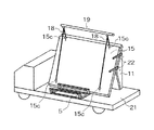
野地板13の2箇所のフック13aにワイヤロープ18をそれぞれ連結し、屋根ユニット11を吊り上げる。ワイヤロープ18はクレーンに連結された横材19にそれぞれフック13aの間隔に相当する間隔で固定されている。屋根ユニット11は垂直端面14を下にして、垂直端面14、軒先部13aを横材19と平行な状態としつつクレーンにより徐々に吊り上げられる。
【0026】
次に、屋根ユニット11を屋根ユニット保持用架台5上まで移動し、図4に示すようにクレーンを徐々に下げつつ垂直端面14を底面としつつ屋根ユニット保持用架台5上に載置する(S.2)。この際、屋根ユニット11が補助枠8aと野地板支持枠7の傾斜部7aとの間になるように降ろしていく。
【0027】
図5に示すように、垂直端面14に備えられた鋼製梁14bには係合ピン9aに対応する位置に係合孔14aが形成されている。この係合ピン9aが係合孔14aに挿通されるように係合ピン9aと係合孔14aとを係合しつつ、野地板12が傾斜部7aに沿って支持されるように屋根ユニット11を載置する。これにより、屋根ユニット11は、垂直端面14を底面として屋根ユニット保持用架台5上に直立保持される。
【0028】
屋根ユニット11を屋根ユニット保持用架台5に載置した後、支持部材16で屋根ユニット11の野地板13を固定する(S.3)。支持部材16は、野地板支持枠7の傾斜部7bに沿うようにして図6(a)中左右2箇所に収納されている。その一端部16aを中心として反対向きに回転させ、図6(a)に示すように支持部材16が傾斜部7bから突出するように位置させることにより、支持部材16によって屋根ユニット11の野地板13を支持する。
【0029】
図6(b)に図6(a)中A部の詳細を示すように、支持部材16の他端部16b近傍には固定ボルトを挿通するための孔16cが形成されている。この孔16cが野地板13の裏面に配された垂木20上になるように位置決めしつつ野地板13にドリルによる孔あけを行い、図示しない固定ボルトとナットにより支持部材16と野地板13とを固定する。屋根ユニット11をクレーンで吊り下げたままの状態で、この支持部材16による野地板13の固定を左右2箇所について行う。
【0030】
支持部材16による野地板13の固定が完了したら、野地板13のフック13aからワイヤロープ18をはずし、ワイヤロープ18を屋根パネル15に設けられた4箇所のフック15cのうち2箇所にそれぞれ連結し、クレーンで吊り上げる。屋根パネル15は軒先部15aを下にして、その軒先部15aを横材19と平行な状態としつつクレーンにより徐々に吊り上げられる。
【0031】
屋根パネル15を屋根ユニット保持用架台5上まで移動し、クレーンを徐々に下げながら軒先部15aを底面としつつ屋根ユニット保持用架台5上に載置する(S.4)。この際、屋根パネル15が補助枠8bと野地板支持枠7の傾斜部7bとの間になるように降ろしていく(図7(a)参照)。
【0032】
軒先部15aには係合ピン9bに対応する位置に係合孔15bが形成されている。この係合ピン9bが係合孔15bに挿通されるように係合ピン9bと係合孔15bとを係合しつつ、屋根パネル15が傾斜部7aに沿って支持されるように屋根パネル15を載置する。屋根パネル15は平板状であり、屋根パネル15の板面は屋根ユニット11の野地板13の板面と平行となるように立てかけられて支持されることとなる。
【0033】
図7(b)に示すように、2枚目の屋根パネル15についてもクレーンで吊り上げて屋根ユニット保持用架台5上に載置するが、その手順は上記1枚目の屋根パネル15の場合と同様であるので説明を省略する。2枚の屋根パネル15が屋根ユニット保持用架台5上に載置された後、屋根ユニット11の側面と屋根パネル15の側面とを、固定金具22(図9参照)で固定する。
【0034】
次に、屋根ユニット11及び2枚の屋根パネル15がその上に載置された屋根ユニット保持用架台5を図8に示すように運送用トラックの荷台21上に積み上げる(S.5)。屋根ユニット保持用架台5には、その底面部6の四隅近傍に4箇所のフック10が設けられている。4本のワイヤロープ18をそれぞれこのフック10に連結し、図示しないクレーンで底面部6の水平を保ちつつ屋根ユニット保持用架台5を荷台21上に積み上げる。屋根ユニット保持用架台5の荷台21への積み上げが完了したら、運送用トラックで屋根ユニット保持用架台5を建築現場まで運送する(S.6)。
【0035】
荷台21には複数の図示しない係合ピンが配置されていて、屋根ユニット保持用架台5を積み上げた際にその底面部6に形成された係合孔と係合するようになっている。この係合ピンと係合孔とが係合することにより、荷台21上の所定の位置に屋根ユニット保持用架台5を載せることができ、運送の際にも屋根ユニット保持用架台5がずれたり不安定になることはない。さらに、屋根ユニット保持用架台5をワイヤロープ等で荷台21にしっかりと固定する。
【0036】
建築現場への運送が完了すると、荷台21から屋根ユニット保持用架台5を降ろすことなく、そのまま屋根パネル15の積み降ろしを行う(S.7)。具体的には以下の手順にて行う。
【0037】
まず、屋根パネル15から固定金具22を外し、屋根パネル15の4箇所のフック15cにそれぞれワイヤロープ18を連結する。このとき、図9に示すように、屋根ユニット保持用架台5に載置された状態での屋根パネル15の片側上下のフック15cに1本のワイヤロープ18を連結し、そのワイヤロープ18を横材19に引っかけるようにする。反対側の上下のフック15cにも同様に1本のワイヤロープ18を連結し、そのワイヤロープ18を横材19に引っかけるようにする。
【0038】
図示しないクレーンで屋根パネル15を吊り上げ、所望の位置まで移動させて降ろす。この際、両側に各1本のワイヤロープ18が横材19に引っかけられてそれぞれ片側上下のフック15cに連結された、いわゆるつるべ式の吊り上げ方式となっているので、吊り上げた状態で、屋根パネル15の姿勢を直立させた状態から横に寝かせた状態へと自由に変更することができる。
【0039】
図10に示すように、2枚目の屋根パネル15についても固定金具22を外し、 図示しないクレーンで吊り上げて所望の位置まで移動させて降ろすが、その手順は1枚目の屋根パネル15の場合と同様であるので詳細は省略する。
【0040】
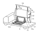
2枚の屋根パネル15の積み降ろしが終了すると、続いて屋根ユニット11の積み降ろしを行う(S.8)。屋根ユニット11の場合も、まず固定金具22を外し、屋根ユニット11の4箇所のフック12a,13aにそれぞれワイヤロープ18を連結する。図11に示すように、屋根ユニット保持用架台5に載置された状態での屋根ユニット11の片側上下のフック13a,12aに1本のワイヤロープ18を連結し、そのワイヤロープ18を横材19に引っかけるようにする。反対側の上下のフック13a,12aにも同様に1本のワイヤロープ18を連結し、そのワイヤロープ18を横材19に引っかけるようにする。
【0041】
図示しないクレーンで屋根ユニット11を吊り上げ、所望の位置まで移動させて降ろす。この際、上述のいわゆるつるべ式の吊り上げ方式となっているので、吊り上げた状態で、屋根ユニット11の姿勢を直立させた状態から横に寝かせた状態へと自由に変更することができる。
【0042】
【発明の効果】
以上説明したように、本願の請求項1に係る発明によれば、棟と平行な垂直端面に係合する係合部と、野地板の傾斜に沿ってその野地板を支持するための野地板支持枠とを有しているので、その垂直端面の面積が小さい屋根ユニットであっても、転倒することなく確実に垂直端面を底面として屋根ユニットを直立させて保持することができる。また、その直立保持の状態のまま、運送用トラックの荷台に積み上げたり、建築現場にまで運送したりすることもできる。
【0043】
請求項2に係る発明によれば、係合部が棟と平行な垂直端面に形成された係合孔に係合する係合ピンであるので、屋根ユニット保持用架台と屋根ユニットとの係合がより確実となり、さらに安定して屋根ユニットの直立保持が可能となる。また、その直立保持状態での運送等もより安定して行うことができる。
【0044】
請求項3に係る発明によれば、平板状の屋根パネルの板面が屋根ユニットの野地板の板面と平行となるように屋根パネルを支持可能であるので、屋根ユニットのみならず屋根パネルをも安定して保持することができる。屋根パネルは屋根ユニットの野地板に立てるように保持することが可能であるので、トラックの荷台からはみ出すことなく運送等を行うこともできる。
【0045】
請求項4に係る発明によれば、屋根ユニットの野地板に固定されて野地板を支持する支持部材が野地板支持枠に収納可能に設けられているので、支持部材によりさらに確実に屋根ユニットを支持できる上に、その支持部材を使用しない場合は収納することができるので邪魔になることもない。
【0046】
請求項5に係る発明によれば、支持部材の一端部が野地板支持枠に枢着され、回動可能に収納可能であるので、請求項4に係る発明が奏する効果に加え、簡単な構造で、容易に収納可能とすることができる。
【図面の簡単な説明】
【図1】本発明の実施の形態に係る屋根ユニット保持用架台の3面図であって、(a)は側方から見た側方図であり、(b)は正面から見た正面図であり、(c)は底面から見た底面図である。
【図2】図1に示す屋根ユニット保持用架台の外観斜視図である。
【図3】屋根ユニットと屋根パネルとを屋根ユニット保持用架台上に載置し、その後この屋根ユニット保持用架台を運送用トラックの荷台に積み上げて建築現場に運送し、建築現場にて屋根ユニット保持用架台から屋根ユニットと屋根パネルとを積み降ろす一連の手順を説明するフローチャートである。
【図4】屋根ユニット保持用架台上に屋根ユニットを載置する様子を示す図である。
【図5】屋根ユニットの棟と平行な垂直端面の係合孔に屋根ユニット保持用架台の係合ピンを係合する様子を示す図である。
【図6】支持部材によって屋根ユニットの野地板を固定する様子を説明する図であって、(a)は収納された支持部材を回転させて野地板を支持する様子を示す図であり、(b)は野地板にドリルによる孔あけを行い、固定ボルトで支持部材と野地板とを固定する様子を示す(a)中A部詳細図である。
【図7】屋根ユニット保持用架台上に屋根パネルを載置する様子を示す図であって、(a)は1枚目の屋根パネルを載置する様子を示す図であり、(b)は2枚目の屋根パネルを載置する様子を示す図である。
【図8】屋根ユニットと屋根パネルとが載置された屋根ユニット保持用架台を運送用トラックの荷台に積み上げる様子を示す図である。
【図9】荷台上の屋根ユニット保持用架台から1枚目の屋根パネルを積み降ろす様子を示す図である。
【図10】荷台上の屋根ユニット保持用架台から2枚目の屋根パネルを積み降ろす様子を示す図である。
【図11】荷台上の屋根ユニット保持用架台から屋根ユニットを積み降ろす様子を示す図である。
【図12】棟を有してその棟から野地板が互いに傾斜して延びる屋根ユニットを示す外観斜視図である。
【符号の説明】
5…屋根ユニット保持用架台
7…野地板支持枠
9a…係合ピン(係合部)
11…屋根ユニット
11a…棟
12,13…野地板
14…棟と平行な垂直端面
14a…係合孔
15…屋根パネル
16…支持部材
16a…一端部[0001]
TECHNICAL FIELD OF THE INVENTION
BACKGROUND OF THE INVENTION 1. Field of the Invention The present invention relates to a roof unit holding rack for holding a vertical upright surface parallel to the ridge as a bottom surface, or transporting the roof unit in the held state.
[0002]
[Prior art]
Conventionally, in a unit building such as a unit house, a roof unit in which a roof beam, a base plate, a small roof panel, etc. are assembled in advance in a manufacturing plant and transported to the building site is transported to the building site. The roof unit is assembled. Also, a roof panel as an exterior member is transported to a construction site after being manufactured at a factory, and the roof unit is assembled to a field board at the construction site.
[0003]
For example, a method has been devised in which a roof unitized in a factory is set up vertically on a truck bed and carried to the site, and the roof is hung from the bed and turned over to a desired posture (for example, Patent Document 1). According to this method, since the roof can be transported upright without lying down, the roof can be transported safely and efficiently without the roof protruding from the bed of the truck.
[0004]
[Patent Document 1]
JP-A-59-42152 [0005]
[Problems to be solved by the invention]
However, according to the method described in Patent Literature 1, when the roof is upright and the surface corresponding to the bottom surface has a large area and is self-supporting, the roof is placed on a truck bed and transported to a construction site. However, for example, as shown in FIG. 12, in the roof unit 1 in which the
[0006]
Even if the roof unit 1 is supported by some kind of support means, the vertical end surface 4 as the bottom surface is small, so that it becomes unstable when it is erected and is transported on a truck bed. It is conceivable to shake and fall.
[0007]
The present invention has been made in view of the above circumstances, and even if the roof unit has a small vertical end surface area parallel to the ridge, the roof unit is erected upright with the vertical end surface as the bottom surface without falling down. An object of the present invention is to provide a roof unit holding frame that can be held.
[0008]
[Means for Solving the Problems]
In order to solve the above problems, a roof unit holding frame according to claim 1 of the present invention has a vertical end surface parallel to a ridge of a roof unit having a ridge and a base plate extending obliquely from the ridge. A roof unit holding base for holding a roof unit upright as a bottom surface, comprising: an engaging portion engaging with a vertical end surface parallel to a ridge; and a field for supporting the field plate along an inclination of the field plate. And a base plate support frame.
[0009]
According to a second aspect of the present invention, there is provided the roof unit holding platform according to the first aspect, wherein the engaging portion engages with an engaging hole formed in a vertical end surface parallel to the ridge. It is characterized by being.
[0010]
According to a third aspect of the present invention, there is provided the roof unit holding frame according to any one of the first and second aspects, wherein the flat surface of the roof panel is a flat plate of the roof unit. The roof panel can be supported so as to be parallel to the surface.
[0011]
The roof unit holding stand according to claim 4 is the roof unit holding stand according to any one of claims 1 to 3, and is fixed to a roof base plate of the roof unit to support the base plate. The support member is provided so as to be accommodated in the base plate support frame.
[0012]
According to a fifth aspect of the present invention, there is provided a roof unit holding base according to the fourth aspect, wherein one end of the support member is pivotally attached to the field board support frame and can be rotatably stored. It is characterized by.
[0013]
BEST MODE FOR CARRYING OUT THE INVENTION
Hereinafter, embodiments of the present invention will be described with reference to the drawings.
[0014]
FIGS. 1A to 1C are three views of a roof
[0015]
Of course, the columnar members constituting the roof unit holding frame are not limited to metal materials, but may be wood or the like. Also, the cross section of the columnar member does not need to be limited to a square, and a columnar member having a circular cross section or an elliptical cross section may be used. Instead of using the columnar member, the pedestal for holding the roof unit may be configured using a plate-like panel.
[0016]
The
[0017]
The
[0018]
The base plate supporting frame 7 is fixed at the center of the
[0019]
[0020]
The
[0021]
The
[0022]
Next, the
[0023]
First, the
[0024]
Two
[0025]
The
[0026]
Next, the
[0027]
As shown in FIG. 5, an
[0028]
After placing the
[0029]
As shown in FIG. 6 (b) in detail in a portion A in FIG. 6 (a), a
[0030]
When the fixing of the
[0031]
The
[0032]
An engagement hole 15b is formed in the
[0033]
As shown in FIG. 7B, the
[0034]
Next, the roof
[0035]
A plurality of engaging pins (not shown) are arranged on the
[0036]
When the transportation to the construction site is completed, the
[0037]
First, the fixing
[0038]
The
[0039]
As shown in FIG. 10, the fixing
[0040]
When the unloading of the two
[0041]
The
[0042]
【The invention's effect】
As described above, according to the invention of claim 1 of the present application, the engaging portion that engages with the vertical end surface parallel to the ridge, and the base plate for supporting the base plate along the slope of the base plate With the support frame, even if the roof unit has a small vertical end surface area, the roof unit can be securely held upright with the vertical end surface as the bottom surface without falling down. In addition, it can be stacked on a carrier of a transport truck or transported to a construction site while being held upright.
[0043]
According to the invention according to
[0044]
According to the invention according to
[0045]
According to the invention according to claim 4, since the support member fixed to the base plate of the roof unit and supporting the base plate is provided so as to be housed in the base plate support frame, the roof member can be more securely held by the support member. In addition to being supportable, when the support member is not used, the support member can be stored, so that there is no hindrance.
[0046]
According to the invention according to
[Brief description of the drawings]
FIG. 1 is a three-sided view of a roof unit holding base according to an embodiment of the present invention, where (a) is a side view as viewed from a side and (b) is a front view as viewed from the front. (C) is a bottom view seen from the bottom.
FIG. 2 is an external perspective view of the rack for holding a roof unit shown in FIG. 1;
[FIG. 3] A roof unit and a roof panel are placed on a roof unit holding frame, and then the roof unit holding frame is stacked on a carrier of a transport truck and transported to a construction site. It is a flowchart explaining a series of procedures of loading and unloading a roof unit and a roof panel from a holding stand.
FIG. 4 is a diagram showing a state in which a roof unit is placed on a roof unit holding stand.
FIG. 5 is a view showing a state in which an engagement pin of a roof unit holding base is engaged with an engagement hole on a vertical end surface parallel to a ridge of a roof unit.
6A and 6B are diagrams illustrating a manner in which a base plate of a roof unit is fixed by a support member, and FIG. 6A is a diagram illustrating a state in which a stored base member is rotated to support a base plate. (b) is a detailed view of part (a) in (a) showing a state in which a hole is drilled in the base plate and the support member and the base plate are fixed with fixing bolts.
FIGS. 7A and 7B are diagrams illustrating a state in which a roof panel is placed on a roof unit holding frame, in which FIG. 7A is a diagram illustrating a state in which a first roof panel is placed, and FIG. It is a figure which shows a mode that a 2nd roof panel is mounted.
FIG. 8 is a diagram showing a manner in which a roof unit holding frame on which a roof unit and a roof panel are placed is stacked on a carrier of a transport truck.
FIG. 9 is a view showing a state in which a first roof panel is unloaded from a roof unit holding base on a loading bed.
FIG. 10 is a diagram showing a state in which a second roof panel is unloaded from a roof unit holding gantry on a cargo bed.
FIG. 11 is a diagram showing a manner in which a roof unit is unloaded from a roof unit holding stand on a cargo bed.
FIG. 12 is an external perspective view showing a roof unit having a building and a base plate extending from the building so as to be inclined with respect to each other.
[Explanation of symbols]
5: Roof unit holding frame 7: Field
11
Claims (5)
前記棟と平行な垂直端面に係合する係合部と、
前記野地板の傾斜に沿ってその野地板を支持するための野地板支持枠とを有することを特徴とする屋根ユニット保持用架台。A roof unit holding frame for holding the roof unit upright with a vertical end surface parallel to the ridge of the roof unit having a ridge and a base plate extending obliquely from the ridge,
An engagement portion that engages with a vertical end surface parallel to the ridge;
A base plate supporting frame for supporting the base plate along the inclination of the base plate; and a gantry for holding a roof unit.
Priority Applications (1)
| Application Number | Priority Date | Filing Date | Title |
|---|---|---|---|
| JP2002314943A JP2004150082A (en) | 2002-10-29 | 2002-10-29 | Retaining stage of roof unit |
Applications Claiming Priority (1)
| Application Number | Priority Date | Filing Date | Title |
|---|---|---|---|
| JP2002314943A JP2004150082A (en) | 2002-10-29 | 2002-10-29 | Retaining stage of roof unit |
Publications (1)
| Publication Number | Publication Date |
|---|---|
| JP2004150082A true JP2004150082A (en) | 2004-05-27 |
Family
ID=32459117
Family Applications (1)
| Application Number | Title | Priority Date | Filing Date |
|---|---|---|---|
| JP2002314943A Withdrawn JP2004150082A (en) | 2002-10-29 | 2002-10-29 | Retaining stage of roof unit |
Country Status (1)
| Country | Link |
|---|---|
| JP (1) | JP2004150082A (en) |
-
2002
- 2002-10-29 JP JP2002314943A patent/JP2004150082A/en not_active Withdrawn
Similar Documents
| Publication | Publication Date | Title |
|---|---|---|
| JP2004150082A (en) | Retaining stage of roof unit | |
| JP2005068650A (en) | Safety handrail | |
| JP3029852U (en) | Hanging video display | |
| JP2000203684A (en) | Transporting stand for panel member with solar cell | |
| JP6046337B2 (en) | Lifting method of outer wall panel | |
| JP2002347829A (en) | Loading base | |
| JPH09235817A (en) | Roof panel and loading structure thereof | |
| JPH0430226Y2 (en) | ||
| JPH11129808A (en) | Building unit loading device | |
| JPH0317350A (en) | Scaffold for building structure | |
| JP2003166345A (en) | Rack for building panel and method for taking out building panel | |
| JPH0451152Y2 (en) | ||
| JP3179246B2 (en) | Overhang unit hanging jig | |
| JP2001262762A (en) | Construction method for roof truss | |
| JPS6340449Y2 (en) | ||
| JPH0547173Y2 (en) | ||
| JP2505380B2 (en) | Lifting mechanism for mobile homes | |
| JP2002347824A (en) | Load mount | |
| JPH09221858A (en) | Fitting method and device for curtain wall | |
| JPH0597244A (en) | Piling up method for roof unit and jig thereof | |
| JPH0825104B2 (en) | Housing unit manufacturing method | |
| JPH09137543A (en) | Manufacture, handling method and manufacturing jig for roof unit | |
| JP2000142857A (en) | Roof panel carrying jig and roof panel carrying method | |
| JPH08119354A (en) | Method and device for storing triangular structural member for building into rack | |
| JP3221782B2 (en) | Fireproof structure and fireproof panel unit of prefabricated building |
Legal Events
| Date | Code | Title | Description |
|---|---|---|---|
| A621 | Written request for application examination |
Effective date: 20050711 Free format text: JAPANESE INTERMEDIATE CODE: A621 |
|
| A761 | Written withdrawal of application |
Free format text: JAPANESE INTERMEDIATE CODE: A761 Effective date: 20060825 |