JP2004149968A - Method for producing three-dimensional fiber structure and apparatus for arranging fiber bundle in circumferential direction of laminated fiber group - Google Patents
Method for producing three-dimensional fiber structure and apparatus for arranging fiber bundle in circumferential direction of laminated fiber group Download PDFInfo
- Publication number
- JP2004149968A JP2004149968A JP2002317302A JP2002317302A JP2004149968A JP 2004149968 A JP2004149968 A JP 2004149968A JP 2002317302 A JP2002317302 A JP 2002317302A JP 2002317302 A JP2002317302 A JP 2002317302A JP 2004149968 A JP2004149968 A JP 2004149968A
- Authority
- JP
- Japan
- Prior art keywords
- fiber
- fiber bundle
- pressing
- dimensional
- laminated
- Prior art date
- Legal status (The legal status is an assumption and is not a legal conclusion. Google has not performed a legal analysis and makes no representation as to the accuracy of the status listed.)
- Pending
Links
Images


Abstract
Description
【0001】
【発明の属する技術分野】
本発明は複数の繊維束層を積層して形成された少なくとも2軸配向となる積層繊維群を、前記繊維束層と直交する方向に配列される厚さ方向糸で結合した、底部と側壁とから成る有底筒状の三次元繊維構造体の製造方法及び積層繊維群の周方向繊維束配列装置に関する。
【0002】
【従来の技術】
繊維強化複合材は軽量の構造材料として広く使用されている。繊維強化複合材のうち、三次元織物(三次元繊維構造体)を強化材として使用したものは強度が非常に高く、航空機等の構造材等に使用が考えられ、一部使用されている。前記三次元繊維構造体の製法として、糸(繊維束)が折り返し状に配列された複数の糸層を積層して少なくとも2軸配向となる積層糸群(積層繊維群)を形成し、その積層糸群を各糸層と直交する方向に配列される厚さ方向糸で結合する製造方法がある(例えば、特許文献1及び特許文献2参照。)。
【0003】
前記特許文献1には、複数の板状部が湾曲部を介して連続する形状、例えばL字状、U字状、コ字状等の異形断面の三次元織物及びその製造方法が開示されている。そして、積層糸群が配列された後、積層糸群を厚さ方向の両側からプレッシャーバーで圧縮して厚さを調整した状態で、積層糸群を構成する各糸層を厚さ方向糸で結合することが開示されている。また、前記プレッシャーバーによる圧縮操作は配列糸の完了後ではなく、糸の配列段階の途中で小刻みに行う方が好ましいと記載されている。
【0004】
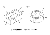
また、特許文献2には、三次元繊維構造体として本願明細書の図9(a),(b)に示す四角箱体、円形箱体のような、底部Fbと側壁Fsとから成る有底筒状の三次元繊維構造体Fも繊維束を積層配列して形成された積層糸群の各糸層を厚さ方向糸で結合することにより製造できる旨が記載されている。
【0005】
【特許文献1】
特開平5−59634号公報(段落番号[0012]〜[0019]、図1〜図5)
【特許文献2】
特開平9−137336号公報(段落番号[0036]〜[0037],[0071]、図19)
【0006】
【発明が解決しようとする課題】
前記の積層糸群を作成した後、厚さ方向糸で各糸層を結合して三次元繊維構造体を製造する方法では、単純に糸(繊維束)を積層した状態では、積層糸群の厚さは製造すべき三次元繊維構造体の厚さの2倍程度の厚さとなる。そして、厚さ方向糸の挿入時に厚さ方向糸に張力をかけることで、積層糸群の各糸層を締め込み、積層糸群を所定の厚さまで薄くして結合するようにしている。
【0007】
三次元繊維構造体がL字状やコ字状の場合は、積層糸群を厚さ方向糸で締め付ける際に、糸の弛みは三次元繊維構造体の端部へと移動するため支障はない。しかし、有底筒状形状(例えば、四角箱状)の場合は、図10に示すように、積層糸群Fcのコーナー部に弛みLが集中して、繊維が蛇行する部分が生じる。繊維の蛇行部が存在する状態で樹脂を含浸させて複合材を製造した場合は、複合材の物性が低下する。特許文献2には有底筒状の三次元繊維構造体も製造できる旨記載されているが、前記弛みに伴う繊維の蛇行を解消する方法に付いては何ら開示されていない。
【0008】
本発明の第1の目的は、積層繊維群を構成する繊維束の配列が完了した状態での積層繊維群の厚さと、厚さ方向糸により各繊維束層を結合した後の厚さとの差を小さくでき、繊維束の蛇行を抑制することができる有底筒状の三次元繊維構造体の製造方法を提供することにある。また、第2の目的は前記有底筒状の三次元繊維構造体を製造する際に好適な積層繊維群の周方向繊維束配列装置を提供することにある。
【0009】
【課題を解決するための手段】
前記第1の目的を達成するため請求項1に記載の発明は、複数の繊維束層を積層して形成された少なくとも2軸配向となる積層繊維群を、前記繊維束層と直交する方向に配列される厚さ方向糸で結合した、底部と側壁とから成る有底筒状の三次元繊維構造体の製造方法である。前記積層繊維群の形成の際に、三次元繊維構造体の外形形状に対応し、かつ少なくとも前記三次元繊維構造体の開口部周縁に対応する位置に沿って規制部材が所定ピッチで設けられた枠体を使用して繊維束の配列を行う。前記繊維束層として前記開口部周縁に設けられた規制部材で折り返して三次元繊維構造体の前記側壁から前記底部に跨るように配列される第1の繊維束層と、前記側壁の周方向に配列される第2の繊維束層とを複数層ずつ形成する。前記第2の繊維束層を形成する際には、三次元繊維構造体の底部を構成するそれまでに積層された繊維束層を押圧部材により押圧して繊維束の弛みを前記側壁側に移動させる。そして、その移動された弛みを三次元繊維構造体の開口部側へ移動させるように当該第2の繊維束層を形成する周方向繊維束を底部側から前記開口部側に向かって順に配列させて前記積層繊維群を形成する。
【0010】
この発明では、三次元繊維構造体の外形形状に対応し、かつ少なくとも前記三次元繊維構造体の開口部周縁に対応する位置に沿って規制部材が所定ピッチで設けられた枠体を使用して、積層繊維群を構成する繊維束の配列が行われる。第1の繊維束層を形成する繊維束は、前記開口部周縁に設けられた規制部材で折り返して三次元繊維構造体の側壁から底部に跨るように配列される。第2の繊維束層を形成する周方向繊維束は、側壁の周方向に配列される。第2の繊維束層を形成する繊維束を配列する際には、三次元繊維構造体の底部を構成するそれまでに積層された第1の繊維束層が押圧部材により押圧されて、繊維束の弛みが、底部の周縁である前記側壁側に移動される。そして、側壁側に移動された弛みを三次元繊維構造体の開口部側へ移動させるように、当該第2の繊維束層を形成する周方向繊維束が底部側から開口側へと順に配列される。その結果、第1の繊維束層を形成する繊維束の弛みが除去される。以下、同様に第2の繊維束層を形成する際に、それまでに積層された第1の繊維束層の繊維束の弛みが除去されるように、周方向繊維束の配列が行われる。その結果、積層繊維群を構成する繊維束の配列が完了した状態での積層繊維群の厚さと、厚さ方向糸により各繊維束層を結合した後の厚さとの差を小さくでき、繊維束の蛇行を抑制することができる。
【0011】
請求項2に記載の発明は、請求項1に記載の発明において、前記第1の繊維束層は繊維束が前記周方向繊維束と直交する方向に配列された層と、繊維束が前記周方向繊維束と傾斜するように配列された層とを備えている。前記枠体は前記三次元繊維構造体の開口部周縁と、底部周縁とに前記規制部材が設けられている。
【0012】
この発明では、底部及び側壁を構成する積層繊維群が面内4軸配列となる。各繊維束層を構成する繊維束は、開口部周縁に設けられた規制部材に巻き掛けられて折り返すように配列されるとともに、底部周縁に設けられた規制部材で配列位置が規制されるため、周方向繊維束と傾斜するように配列される際も、所定の位置に良好に配列される。
【0013】
請求項3に記載の発明は、請求項1又は請求項2に記載の発明において、前記第2の繊維束層を形成する周方向繊維束を配列する際、周方向繊維束の配列前に前記側壁と対応する位置に配列された第1の繊維束層を押圧体で押圧しつつ該押圧体を第1の繊維束層を構成する繊維束の配列方向に沿って移動させる。この発明では、押圧体が第1の繊維束層を構成する繊維束の配列方向に沿って移動されるため、繊維束の弛みを開口部側に効率良く移動させることができる。
【0014】
第2の目的を達成するため請求項4に記載の発明は、複数の繊維束層を積層して形成された少なくとも2軸配向となる積層繊維群を、前記繊維束層と直交する方向に配列される厚さ方向糸で結合した、底部と側壁とから成る有底筒状の三次元繊維構造体を形成するための積層繊維群の周方向繊維束配列装置である。周方向繊維束配列装置は、保持装置と、第1の押圧機構と、第2の押圧機構と、繊維束供給部とを備えている。保持装置は、前記三次元繊維構造体の外形形状に対応し、かつ少なくとも前記三次元繊維構造体の開口部周縁に対応する位置に沿って規制部材が所定ピッチで設けられた枠体を保持するとともに駆動手段により回転駆動可能となっている。第1の押圧機構は、前記保持装置に保持された枠体上に配列された繊維束層の前記三次元繊維構造体の底部に対応する箇所を押圧する押圧位置と、前記押圧位置から退避した待機位置とに配置される押圧部材を備えている。第2の押圧機構は、前記保持装置に保持された枠体上に配列された繊維束層の前記三次元繊維構造体の側壁に対応する箇所を押圧しつつ移動する作用位置と、前記作用位置から退避した待機位置とに配置される押圧体を備えている。繊維束供給部は、前記枠体上の前記三次元繊維構造体の側壁に対応する位置に配列される繊維束を供給する。
【0015】
この発明の周方向繊維束配列装置では、規制部材が所定ピッチで設けられた枠体が保持装置に保持される。枠体上の三次元繊維構造体の底部に対応する箇所に配列された繊維束層は、第1の押圧機構の押圧部材により押圧され、繊維束の弛みが底部周縁である前記側壁側に移動される。前記側壁側に移動された弛みは、第2の押圧機構の押圧体により押圧されて開口側へ移動される。また、繊維束供給部から供給される繊維束は、前記保持装置が回転駆動されることにより、前記枠体上の前記三次元繊維構造体の側壁に対応する位置に周方向に延びるように配列される。従って、この周方向繊維束配列装置を使用することにより、底部と側壁とから成る有底筒状の三次元繊維構造体を形成する積層繊維群の周方向繊維束の配列を、周方向繊維束と交差するように配列された繊維束の弛みを開口側に移動させる(逃がす)ように円滑に行うことができる。
【0016】
【発明の実施の形態】
(第1の実施の形態)
以下、本発明を有底四角筒状(四角箱状)の三次元繊維構造体を製造する場合に具体化した第1の実施の形態を図1〜図7及び図9(a)に従って説明する。
【0017】
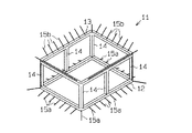
先ず三次元繊維構造体の製造に使用する枠体の構成を説明する。図2は枠体の模式斜視図である。この枠体は三次元繊維構造体の形状に対応した積層繊維群の形成と、形成された積層繊維群への厚さ方向糸の挿入時における積層繊維群の保持とに使用される。
【0018】
図2に示すように、枠体11は、互いに平行に配置された長方形状の一組の枠部12,13を複数本(この実施の形態では6本)の連結部14で連結して直方体形状に形成されている。即ち、枠体11は、有底四角筒状の三次元繊維構造体の外形形状に対応して形成されている。この実施の形態では図2における、下側の枠部12が三次元繊維構造体の開口部周縁に対応し、上側の枠部13が三次元繊維構造体の底部周縁に対応する。枠部12には多数の規制部材15aが所定ピッチで取り外し可能に設けられ、枠部13には多数の規制部材15bが所定ピッチで取り外し可能に設けられている。規制部材15a,15bは、例えばピンで形成されている。
【0019】
枠部12に設けられた規制部材15aは、枠部12を含む平面とほぼ平行又は枠部13と反対側へ多少傾斜する状態(図2では多少下降傾斜する状態)で外側に突出するように設けられている。枠部13に設けられた規制部材15bは、枠部12を含む平面と、枠部13の一辺、当該一辺と対向する枠部12の一辺及び両辺を連結する連結部14を含む平面に対してほぼ45°の角度を成して外側に突出するように設けられている。
【0020】
枠部12に設けられた規制部材15aは、三次元繊維構造体の底部及び側壁に跨るように配列される繊維束の折り返し位置と、配列位置とを規制する役割を果たす。枠部13に設けられた規制部材15bは、三次元繊維構造体の底部及び側壁に跨るように配列される繊維束の配列位置を規制する役割を果たす。
【0021】
次に前記枠体11上に有底筒状の三次元繊維構造体を形成するための積層繊維群の周方向繊維束を配列する周方向繊維束配列装置について説明する。図1に示すように、周方向繊維束配列装置16は保持装置17と、第1の押圧機構18と、第2の押圧機構19と、繊維束供給部20とを備えている。
【0022】
保持装置17は、枠体11を保持する回転テーブル21と、駆動手段としてのモータ22とを備えている。回転テーブル21は、枠体11の底面、即ち図1における枠部12の下面を支承する部分21aと、枠体11の内側に挿入されて枠体11の内面に当接する部分21bとを備えている。モータ22は回転テーブル21を回転させる。即ち、回転テーブル21は、枠体11を保持した状態で駆動手段により回転駆動可能となっている。
【0023】
第1の押圧機構18は、保持装置17に保持された枠体11上に配列された繊維束層の三次元繊維構造体の底部に対応する箇所を押圧する押圧位置と、前記押圧位置から退避した待機位置(図1に示す位置)とに配置される押圧部材23を備えている。この実施の形態では、第1の押圧機構18は回転テーブル21の上方に配設されている。押圧部材23はエアシリンダ24のピストンロッド24aに固定され、エアシリンダ24の作動によって前記押圧位置と待機位置とに配置されるようになっている。
【0024】
押圧部材23は、枠部13に設けられた規制部材15bで囲まれる範囲をほぼ覆う大きさの長方形状の金属製の支持板23aと、支持板23aの片面(図1では下面)に固着された押圧部23bとから構成されている。押圧部23bは発泡樹脂製で、支持板23aに対向する面と反対側の面(押圧面)が押圧位置に配置されて支持板23aから押圧力を受けた場合に、前記押圧面が中央部から外側へ向かって拡がるように変形可能に形成されている。例えば、図1に示すように、押圧部23bの押圧面側に多数の切り込み25が形成されている。
【0025】
第2の押圧機構19は、保持装置17に保持された枠体11上に配列された繊維束層の三次元繊維構造体の側壁に対応する箇所を押圧しつつ移動する作用位置と、前記作用位置から退避した待機位置とに配置される押圧体26を備えている。図1,3に示すように、押圧体26は水平に配設されたエアシリンダ27のピストンロッド27aにスライド機構28を介して取り付けられ、エアシリンダ27の作動によって前記作用位置と待機位置とに配置されるようになっている。
【0026】
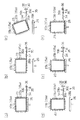
図1,3に示すように、スライド機構28は、ピストンロッド27aに固定された基板29に対して相対回動可能かつ図示しないボルトで所定位置に固定された支持部材30と、支持部材30に摺動可能に連結支持されたスライド部材31とを備えている。支持部材30は円柱の一端を斜めに(この実施の形態では軸線と45度の角度を成すように)切断した形状に形成され、先端面には図4(b),(c)に示すように、中心を通り直線状に延びるガイド溝30aが形成されている。また、支持部材30には、軸心と直交する状態で一端がガイド溝30aと対応する位置に開口し、他端が周面に開口する孔30bが形成されている。
【0027】
スライド部材31も円柱の一端を斜めに(この実施の形態では軸線と45度の角度を成すように)切断した形状に形成され、図4(a)に示すように、支持部材30の先端面と対向する端面にガイド溝30aに係合可能な凸条31aが形成されている。また、スライド部材31には、軸心と直交する状態で一端が凸条31aの中央と対応する位置に開口し、他端が周面に開口するねじ孔31bが形成されている。ねじ孔31bには図1,3に示すように、支持部材30の孔30bを貫通したボルト32の先端部が螺合されている。ボルト32の頭部と支持部材30の周面との間にはコイルばね33が介装され、スライド部材31に重力以外の力が作用しない状態では、コイルばね33によりボルト32を介してスライド部材31が図1,3に示す所定の位置に保持されるようになっている。孔30bはボルト32の移動を許容するように形成されている。
【0028】
押圧体26は、スライド部材31に固定された支持板26aと、支持板26aの片面に固着された押圧部26bとから構成されている。押圧部26bは図1,3における上下方向の長さ、即ち高さが、枠体11の高さより若干小さく形成され、幅(図1,3の紙面と垂直方向の長さ)が枠体11の長さと同じに形成されている。押圧部26bは発泡樹脂製で、支持板26aに対向する面と反対側の面(押圧面)が作用位置に配置されて支持板26aから押圧力を受けた場合に、押圧面が繊維束を傷つけずに押圧するように形成されている。
【0029】
繊維束供給部20は、第2の押圧機構19と対向する位置に配設され、枠体11上の三次元繊維構造体の側壁に対応する位置に配列される繊維束Rを供給するようになっている。繊維束供給部20は、繊維束供給ヘッド34、張力付与部35及び把持ローラ36を備えた支持プレート37が、支柱38に沿って上下方向に往復移動可能に設けられている。支持プレート37は繊維束供給ヘッド34の移動範囲が、枠体11の高さの範囲となるように図示しないアクチュエータにより駆動されるようになっている。繊維束供給ヘッド34は図示しないボビンから繰り出されるとともに張力付与部35を経て供給される繊維束Rを扁平な状態で送り出すように先端が扁平に形成された筒状体で構成されている。
【0030】
張力付与部35は、把持ローラ36と繊維束供給ヘッド34との間に設けられ、繊維束Rの供給方向に直交するように配設された3本一組のローラ39a,39b,39cを備えている。把持ローラ36は繊維束Rを把持する把持位置と、繊維束Rの移動を許容する開放位置とに移動されるようになっている。ローラ39bは図示しないアクチュエータにより昇降可能に構成され、繊維束Rが把持ローラ36に把持された状態で、ローラ39bがローラ39a,39c間に位置する繊維束Rと係合して張力を付与するようになっている。
【0031】
次に前記のように構成された枠体11及び周方向繊維束配列装置16を使用して、枠体11上に繊維束Rを折り返し状に配列して、図9(a)に示すような底部Fbと側壁Fsとから成る有底筒状の三次元繊維構造体Fを構成する積層繊維群を形成する際の作用を説明する。
【0032】
図5(a)は、枠体11上に、枠体11の開口部周縁に設けられた規制部材で折り返して三次元繊維構造体の側壁から底部に跨るように、かつ繊維束Rが周方向繊維束と直交する方向に配列された第1の繊維束層40aの配列状態を示す模式図である。図5(b)は、枠体11上に、枠体11の開口部周縁に設けられた規制部材で折り返して三次元繊維構造体の側壁から底部に跨るように、かつ繊維束Rが周方向繊維束と傾斜するように配列された第1の繊維束層40bの配列状態を示す模式図である。なお、図5(a),(b)では規制部材15a,15bの図示を省略しており、分かりやすくするため繊維束Rの間隔を広くとって示している。図6(a)〜(f)は、周方向繊維束の配列作用を示す模式平面図である。なお、図示の都合上、図6(a)〜(f)では枠体11に対する第2の押圧機構19と繊維束供給部20との関係が、図1の場合と異なる状態で示している。
【0033】
先ず図1に示すように、保持装置17の回転テーブル21に、枠体11をその枠部13を上にした状態で保持する。次に繊維束供給ヘッド34が枠部13と対応する状態となる位置に支持プレート37を配置する。次にボビンから繰り出した繊維束Rを、把持ローラ36及び張力付与部35を経て繊維束供給ヘッド34に挿通して、繊維束Rの端部を繊維束供給ヘッド34の先端から引き出す。そして、繊維束Rの先端を枠体11の所定位置、例えば枠部12に固定する。繊維束Rの固定は、例えば図示しない接着テープを使用して行う。この繊維束Rは、三次元繊維構造体の側壁の周方向に配列される第2の繊維束層を構成するものとなる。
【0034】
また、三次元繊維構造体の側壁から底部に跨るように配列される第1の繊維束層40a,40bを構成する繊維束Rを別の図示しないボビンから繰り出し、その端部を枠体11の所定位置、例えば枠部13に固定する。繊維束Rの固定は、例えば図示しない接着テープを使用して行う。以上で積層繊維群を構成する準備が終了する。なお、繊維束Rは炭素繊維の無撚りのマルチフィラメントからなり、マルチフィラメントはフィラメント数が3000〜24000本程度である。
【0035】
次にその状態で先ず第1の繊維束層40aの配列が開始される。第1の繊維束層の配列は手作業あるいは多軸ロボットのアームに繊維束供給ヘッドを装備した装置による作業により行われる。繊維束Rを開口部周縁、即ち枠部12に設けられた規制部材15aで折り返して三次元繊維構造体の側壁から底部に跨るように、かつ枠体11の周方向に配列される周方向繊維束と直交する方向に配列された図5(a)に示す第1の繊維束層40aが形成される。次に、繊維束Rが周方向繊維束と傾斜するように配列された図5(b)に示す第1の繊維束層40bが形成される。これらの繊維束層40a,40bを形成する際、繊維束Rは枠体11の枠部12に設けられた規制部材15aと、枠部13に設けられた規制部材15bとによって位置が規制されて配列される。
【0036】
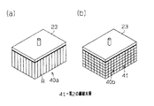
第1の繊維束層40a,40bの一方が形成される毎に第1の押圧機構18が駆動され、押圧部材23が待機位置から押圧位置に移動される。そして、図7(a),(b)に示すように、枠体11上の三次元繊維構造体の底部に対応する箇所に配列された繊維束層は、押圧部材23により押圧され、繊維束Rの弛みが底部周縁である側壁側(枠部13側)に移動される。図7(a)は第1の繊維束層40aが配列された状態で押圧部材23が押圧位置に配置された状態を示し、図7(b)はその後、第2の繊維束層41が形成された状態を示している。
【0037】
次に第2の押圧機構19が駆動され、図6(a)に示すように、押圧体26が待機位置から作用位置に移動される。押圧体26は、押圧部26bが第1の繊維束層40a,40bと係合するまでは直進し、その後、スライド機構28の作用により、開口部側へ移動される。移動方向は予め支持部材30の取り付け状態によって決まり、周方向繊維束を配列する前の第1の繊維束層40a,40bの繊維束Rの配列方向に移動される。即ち、繊維束Rの配列が図5(a)に示す第1の繊維束層40aであれば、押圧体26は下方へ移動され、繊維束Rの配列が図5(b)に示す第1の繊維束層40bの場合であれば、斜め45度傾いた方向へ押圧体26は移動される。
【0038】
次に図6(b)に示すように押圧体26が待機位置に移動された後、図6(c),(d)に示すように、把持ローラ36による繊維束Rの把持及び張力付与部35のローラ39a〜39cとの係合が解除された状態で、回転テーブル21が90度回転されて周方向繊維束としての繊維束Rが配列される。次に図6(e)に示すように、再び押圧体26が作用位置に移動され、押圧部26bによる配列面の加圧と、第1の繊維束層40a,40bの弛みの移動が行われる。その後、図6(f)に示すように、把持ローラ36が把持位置に移動されるとともに、ローラ39bが張力付与位置に移動され、配列中の繊維束Rの弛みが除去される。
【0039】
以下、同様にして、押圧体26の待機位置への移動、繊維束Rの把持が解除された状態における回転テーブル21の90度の回転、押圧体26の作用位置への移動、張力付与部35による繊維束Rへの張力の付与が繰り返される。そして、回転テーブル21が一回転した時点で、周方向繊維束としての繊維束Rの最初の1周分の配列が完了する。次に支持プレート37が下降されて繊維束供給ヘッド34が1ピッチ分ずれた位置へ移動され、その状態で再び前記と同様にして繊維束Rの配列が行われる。そして、繊維束Rが三次元繊維構造体の底部側から順に配列されることにより、第1の繊維束層40a,40bの弛みが除去される。
【0040】
図7(b)に示すように、1層分の第2の繊維束層41の形成が完了すると、押圧部材23及び押圧体26が待機位置に移動された後、再び第1の繊維束層40a,40bの形成が行われる。そして、枠体11上に第1の繊維束層40a,40b及び第2の繊維束層41が所定の順序で所定数積層されて積層繊維群が形成される。
【0041】
積層繊維群が形成された後、枠体11は積層繊維群とともに回転テーブル21から取り外され、厚さ方向糸挿入装置にセットされる。そして、厚さ方向糸挿入装置により第1の繊維束層40a,40b及び第2の繊維束層41と直交するように厚さ方向糸が積層繊維群に挿入され、積層繊維群が結合されて、図9(a)に示すような有底四角筒状(箱状)の三次元繊維構造体Fの製造が完了する。積層繊維群が形成された状態の厚みと、厚さ方向糸が挿入されて三次元繊維構造体Fとなった状態の厚みとの差が7%以下となった。
【0042】
なお、枠体11上に配列された繊維束Rを分かり易くするため、隣接する繊維束Rが隙間を有するように図示しているが、実際は隣接する繊維束Rの間に隙間は殆ど無い状態に配列される。また、規制部材15a,15bは、その間隔が実際は繊維束Rの太さと同程度となるように設けられる。
【0043】
この実施の形態では次の効果を有する。
(1) 底部と側壁とから成る有底筒状の三次元繊維構造体を構成する積層繊維群の形成の際に、側壁から底部に跨るように配列される第1の繊維束層40a,40bと、側壁の周方向に配列される第2の繊維束層41とを複数層ずつ形成する。第2の繊維束層41を形成する際には、三次元繊維構造体の底部を構成するそれまでに積層された繊維束層を押圧部材23により押圧して繊維束の弛みを側壁側に移動させる。そして、その移動された弛みを三次元繊維構造体の開口部側へ移動させるように第2の繊維束層41を形成する周方向繊維束を底部側から前記開口部側に向かって順に配列させて積層繊維群を形成する。従って、第2の繊維束層41を形成する際に、第1の繊維束層40a,40bの繊維束の弛みが確実に除去され、積層繊維群を構成する繊維束の配列が完了した状態での積層繊維群の厚さと、厚さ方向糸により各繊維束層を結合した後の厚さとの差を小さくでき、繊維束の蛇行を抑制することができる。その結果、前記積層繊維群に厚さ方向糸を挿入して製造した三次元繊維構造体を強化材とした複合材の物性が向上する。
【0044】
(2) 第1の繊維束層40a,40bは繊維束が周方向繊維束と直交する方向に配列された層と、繊維束が周方向繊維束と傾斜するように配列された層とを備えているため、底部及び側壁を構成する積層繊維群が面内4軸配列となり、面内2軸配列に比較して物性が向上する。
【0045】
(3) 枠体11は三次元繊維構造体の開口部周縁に対応する箇所即ち枠部12と、底部周縁に対応する箇所即ち枠部13とに規制部材15a,15bが設けられている。そして、積層繊維群の第1の繊維束層40a,40bを構成する繊維束は、枠部12に設けられた規制部材15aに巻き掛けられて折り返すように配列されるとともに、枠部13に設けられた規制部材15bで配列位置が規制される。従って、周方向繊維束と傾斜するように配列される際も、所定の位置に良好に配列される。
【0046】
(4) 第2の繊維束層41を形成する周方向繊維束を配列する際、周方向繊維束の配列前に側壁と対応する位置に配列された第1の繊維束層40a,40bを押圧体26で押圧しつつ該押圧体26を第1の繊維束層を構成する繊維束Rの配列方向に沿って移動させる。従って、押圧体26が第1の繊維束層40a,40bを構成する繊維束Rの配列方向に沿って移動されるため、繊維束Rの弛みを開口部側に効率良く移動させることができる。
【0047】
(5) 周方向繊維束配列装置16は、枠体11を保持してモータ22により回転駆動可能な保持装置17と、第1の繊維束層40a,40bの三次元繊維構造体の底部に対応する箇所を押圧する押圧位置と、待機位置とに配置される押圧部材23を備えた第1の押圧機構18とを備えている。また、保持装置17に保持された枠体11上に配列された繊維束層の三次元繊維構造体の側壁に対応する箇所を押圧しつつ移動する作用位置と、作用位置から退避した待機位置とに配置される押圧体26を備えた第2の押圧機構19を備えている。枠体11上の三次元繊維構造体の側壁に対応する位置に配列される繊維束を供給する繊維束供給部20とを備えている。従って、この周方向繊維束配列装置16を使用することにより、底部と側壁とから成る有底筒状の三次元繊維構造体を形成する積層繊維群の周方向繊維束の配列を、周方向繊維束と交差するように配列された繊維束の弛みを開口側に移動させる(逃がす)ように円滑に行うことができる。
【0048】
(6) 三次元繊維構造体の底部に対応する箇所を押圧する押圧部材23は、第1の繊維束層に押圧されると中央から周縁に向かって拡がる作用をなす押圧部26bを備えている。従って、第1の繊維束層40a,40bを形成するために配列された繊維束Rの弛みを円滑に周縁部に移動させることができる。
【0049】
(7) 第2の押圧機構19の押圧体26がスライド機構28を介してピストンロッド27aに支持され、ピストンロッド27aの突出作動により押圧部26bが第1の繊維束層40a,40bに押圧された状態で繊維束の弛みを前記開口側へ移動させる方向へスライドされる。従って、押圧体26を待機位置と作用位置との間で移動させるアクチュエータのみで、押圧体26のスライド動作も行わせることができスライド用のアクチュエータを別に設ける必要がない。
【0050】
(8) 枠体11上に積層繊維群が形成され、積層繊維群に厚さ方向糸を挿入する際も同じ枠体11に積層繊維群を保持した状態で行うことができ、三次元繊維構造体の製造が完了するまで枠体11を代える必要がない。
【0051】
なお、実施の形態は前記に限定されるものではなく、例えば、次のように具体化してもよい。
○ 回転テーブル21に枠体11を保持し、周方向繊維束としての繊維束Rの配列を回転テーブル21を回転駆動することで行う構成に代えて、枠体11を所定位置に固定保持し、繊維束供給ヘッド34側を移動させる構成としてもよい。例えば、図8に示すように、枠体11を保持するテーブルは所定位置に固定配置され、繊維束供給部20が枠体11の周囲を所定方向に回転して、枠体11の側面に周方向繊維束としての繊維束Rを配列する構成とする。この構成では支持プレート37及び支柱38(いずれも図示せず)がテーブルの周囲に沿って移動可能に構成される。また、第2の押圧機構19が枠体11の各側面と対向する位置にそれぞれ設けられている。そして、周方向繊維束の繊維束Rの配列は、押圧体26の作用位置への移動、押圧体26の待機位置への移動、繊維束供給ヘッド34等の移動による繊維束Rの配列、繊維束Rへの張力付与の各動作が順次行われて、枠体11の一つの側面への繊維束Rの配列が完了する。以下、同様の動作が4回繰り返されて、繊維束供給ヘッド34等が一回転した時点で、周方向繊維束としての繊維束Rの最初の1周分の配列が完了する。そして、繊維束供給ヘッド34の位置を1ピッチずらした状態で、前記と同様に周方向繊維束の繊維束Rの配列が行われる。
【0052】
〇 三次元繊維構造体の底部を構成するそれまでに積層された第1の繊維束層40a,40bの繊維束の弛みを側壁側に移動させる構成は、押圧部材23の押圧部23bを発泡樹脂製としてその押圧面側に多数の切り込み25を形成した構成に限らない。例えば、底部より面積の小さな押圧部23bを設け、押圧部23bを押圧位置に配置した状態で、中央から周縁側に向かって渦を描くように移動させる構成としてもよい。この場合も第1の繊維束層40a,40bの繊維束Rの弛みが円滑に除去される。
【0053】
〇 第1の繊維束層40a,40bを繊維束が周方向繊維束と直交する方向に配列された層と、繊維束が前記周方向繊維束と傾斜するように配列された層との何れか一方のみとし、積層繊維群を面内2軸配列としてもよい。第1の繊維束層を繊維束が周方向繊維束と直交する方向に配列された層のみで構成する場合、枠体11は枠部12にのみ規制部材15aを設けた構成としてもよい。この場合、枠体11の構造が簡単になる。
【0054】
〇 張力付与用のローラ39a〜39cを繊維束供給ヘッド34と、把持ローラ36との間に配置する構成に代えて、ローラ39a〜39cを枠体11に最も近い位置に配設し、ローラ39a〜39cと把持ローラ36との間に繊維束供給ヘッド34を配置する構成としてもよい。
【0055】
〇 第2の押圧機構19として、押圧体26が1個のアクチュエータの作動により、作用位置に配置された際に自動的にアクチュエータの往復移動方向と直交する方向に移動可能なスライド機構28を設けずに、2個のアクチュエータを備えた構成としてもよい。例えば、ピストンロッド27aの先端に支持プレートを固定し、支持プレートにピストンロッド27aと直交する方向に押圧体26を移動させるアクチュエータを設ける。
【0056】
〇 周方向繊維束としての繊維束Rを配列する前に第2の押圧機構19の押圧部26bを作用位置でスライドさせる構成において、スライド方向は必ずしも、その前に配列された第1の繊維束層40a,40bを構成する繊維束Rの配列方向と一致させなくてもよい。しかし、一致させる方が、弛みを円滑に移動させ易い。
【0057】
〇 積層繊維群の構成は、周方向繊維束で形成される第2の繊維束層41と、第1の繊維束層40a,40bとを交互に配列した構成に限らない。例えば、底部において繊維束Rが互いに直交し、かつ側壁において周方向繊維束と直交する第1の繊維束層40aと、側壁において周方向繊維束と斜めに交差する第1の繊維束層40bとが少なくとも1層ずつ配列された後、第2の繊維束層41を形成してもよい。
【0058】
〇 アクチュエータはエアシリンダに限らず、リニアアクチュエータを使用してもよい。
○ 規制部材15a,15bとしてピンに代えてパイプを使用したり、ピンやパイプのように棒状の物に限らず、板状のものを使用してもよい。但し板状のものを使用する場合は、底部において繊維束Rが互いに直交し、かつ側壁において周方向繊維束と斜めに交差する第1の繊維束層40bを設けない構成の積層繊維群を形成する際に使用される枠体11となる。第1の繊維束層40bを形成する場合は、規制部材15a,15bとしてピン又はパイプが使用される。
【0059】
○ 繊維束供給ヘッド34は1本の繊維束Rを供給、配列する構成に限らず、複数本の繊維束Rを同時に配列する構成としてもよい。この場合、1本の繊維束Rを順次配列する場合に比較して、繊維束Rの配列時間を大幅に短縮することができる。
【0060】
○ 張力付与部35は繊維束Rを把持した状態で、3個一組のローラ39a〜39cで繊維束Rに張力を付与する構成に限らず、例えば、繊維束Rに巻き戻し方向の力を付与する構成としてもよい。
【0061】
○ 繊維束Rとして炭素繊維に限らず、複合材の用途に応じてボロン繊維、炭化ケイ素繊維等の無機繊維を使用したり、ポリアラミド繊維、超高分子量ポリエチレン繊維などの高強度・高弾性率の有機繊維の無撚りマルチフィラメントを使用してもよい。
【0062】
前記実施の形態から把握される発明(技術的思想)について以下に記載する。(1) 請求項1に記載の発明において、前記押圧部材は発泡樹脂製で第1の繊維束層と対向する面に、押圧部材が第1の繊維束層に押圧されると中央から周縁に向かって拡がる作用をなす複数の切れ込みが形成されている。
【0063】
(2) 請求項4に記載の発明において、前記第2の押圧機構は、前記押圧体が前記側壁に対応する箇所を押圧する位置に配置された状態で、前記押圧体を自動的に繊維束の弛みを前記開口部周縁側に移動させる方向に移動される。
【0064】
【発明の効果】
以上、詳述したように、請求項1〜請求項3に記載の発明によれば、積層繊維群を構成する繊維束の配列が完了した状態での積層繊維群の厚さと、厚さ方向糸により各繊維束層を結合した後の厚さとの差を小さくでき、繊維束の蛇行を抑制することができる。また、請求項4に記載の発明によれば、前記有底筒状の三次元繊維構造体を製造する際に好適な積層繊維群の周方向繊維束の配列を行うことができる。
【図面の簡単な説明】
【図1】周方向繊維束配列装置の模式正面図。
【図2】枠体の模式斜視図。
【図3】第2の押圧機構の模式側面図。
【図4】(a)はスライド部材の模式斜視図、(b)は支持部材及びスライド部材の関係を示す模式分解図、(c)は支持部材の模式斜視図。
【図5】(a)は第1の繊維束層の繊維束配列状態を示す模式斜視図、(b)は同じく別の第1の繊維束層の繊維束配列状態を示す模式斜視図。
【図6】(a)〜(f)は作用を説明する模式平面図。
【図7】(a)は押圧部材が作用位置に配置された状態を示す模式斜視図、(b)は周方向繊維束が配列された状態を示す模式斜視図。
【図8】別の実施の形態の模式平面図。
【図9】(a),(b)は有底筒状の三次元繊維構造体の模式斜視図。
【図10】従来の厚さ方向糸挿入終了時の繊維束の状態を示す模式斜視図。
【符号の説明】
F…三次元繊維構造体、Fb…底部、Fs…側壁、R…繊維束、11…枠体、15a,15b…規制部材、16…周方向繊維束配列装置、17…保持装置、18…第1の押圧機構、19…第2の押圧機構、20…繊維束供給部、23…押圧部材、26…押圧体、40a,40b…第1の繊維束層、41…第2の繊維束層。[0001]
TECHNICAL FIELD OF THE INVENTION
The present invention combines a laminated fiber group having at least biaxial orientation formed by laminating a plurality of fiber bundle layers, with a thickness direction thread arranged in a direction orthogonal to the fiber bundle layer, a bottom portion and a side wall. And a device for arranging circumferential fiber bundles of a laminated fiber group.
[0002]
[Prior art]
Fiber reinforced composites are widely used as lightweight structural materials. Among fiber-reinforced composite materials, those using a three-dimensional woven fabric (three-dimensional fiber structure) as a reinforcing material have extremely high strength, and are considered to be used for structural materials of aircraft and the like, and are partially used. As a method of manufacturing the three-dimensional fiber structure, a plurality of yarn layers in which yarns (fiber bundles) are arranged in a folded shape are laminated to form a laminated yarn group (laminated fiber group) having at least biaxial orientation. Are bonded by a thickness direction yarn arranged in a direction orthogonal to each yarn layer (for example, see Patent Documents 1 and 2).
[0003]
Patent Literature 1 discloses a three-dimensional woven fabric having a shape in which a plurality of plate-shaped portions are continuous via a curved portion, for example, an L-shaped, U-shaped, or U-shaped, and a method for manufacturing the same. I have. Then, after the laminated yarn group is arranged, the respective yarn layers constituting the laminated yarn group are joined with the thickness direction yarns in a state where the laminated yarn group is compressed from both sides in the thickness direction with a pressure bar to adjust the thickness. Is disclosed. Further, it is described that the compression operation by the pressure bar is preferably performed in small increments during the yarn arrangement stage, not after completion of the arrangement yarns.
[0004]
In addition, Patent Document 2 discloses a three-dimensional fiber structure having a bottom having a bottom Fb and a side wall Fs, such as a rectangular box or a circular box shown in FIGS. 9A and 9B of the present specification. It is described that a cylindrical three-dimensional fiber structure F can also be manufactured by combining the yarn layers of a laminated yarn group formed by laminating and arranging fiber bundles with a thickness direction yarn.
[0005]
[Patent Document 1]
JP-A-5-59634 (paragraph numbers [0012] to [0019], FIGS. 1 to 5)
[Patent Document 2]
JP-A-9-137336 (paragraph numbers [0036] to [0037], [0071], FIG. 19)
[0006]
[Problems to be solved by the invention]
In the method of manufacturing the three-dimensional fiber structure by combining the respective yarn layers with the thickness direction yarns after creating the above-described laminated yarn group, the thickness of the laminated yarn group is determined in a state where the yarns (fiber bundles) are simply laminated. Is about twice the thickness of the three-dimensional fiber structure to be manufactured. Then, by applying a tension to the thickness direction yarn when the thickness direction yarn is inserted, each yarn layer of the layered yarn group is tightened, and the layered yarn group is thinned to a predetermined thickness and joined.
[0007]
When the three-dimensional fiber structure has an L-shape or a U-shape, when the laminated yarn group is fastened with the thickness direction yarn, the slack of the yarn moves to the end of the three-dimensional fiber structure, so that there is no problem. However, in the case of a bottomed cylindrical shape (for example, a square box shape), as shown in FIG. 10, the slack L is concentrated at the corners of the laminated yarn group Fc, and a portion where the fibers meander is generated. When the composite material is manufactured by impregnating the resin with the meandering portion of the fiber, the physical properties of the composite material deteriorate. Patent Document 2 describes that a cylindrical bottomed three-dimensional fiber structure can also be produced, but does not disclose any method for eliminating the meandering of the fiber due to the loosening.
[0008]
A first object of the present invention is to provide a difference between the thickness of a laminated fiber group in a state where the arrangement of the fiber bundles constituting the laminated fiber group is completed, and the thickness after the respective fiber bundle layers are combined by the thickness direction yarn. It is an object of the present invention to provide a method of manufacturing a bottomed cylindrical three-dimensional fiber structure which can reduce the meandering of the fiber bundle and suppress the meandering of the fiber bundle. It is a second object of the present invention to provide an apparatus for arranging circumferential fiber bundles of a group of laminated fibers which is suitable for producing the bottomed cylindrical three-dimensional fiber structure.
[0009]
[Means for Solving the Problems]
In order to achieve the first object, the invention according to claim 1, wherein a group of laminated fibers having at least biaxial orientation formed by laminating a plurality of fiber bundle layers is arranged in a direction orthogonal to the fiber bundle layers. This is a method for producing a bottomed cylindrical three-dimensional fiber structure composed of a bottom portion and a side wall, which are connected by arranged thickness direction yarns. At the time of forming the laminated fiber group, regulating members were provided at a predetermined pitch corresponding to the outer shape of the three-dimensional fiber structure, and at least along a position corresponding to the periphery of the opening of the three-dimensional fiber structure. The fiber bundle is arranged using the frame. A first fiber bundle layer arranged so as to be folded from the side wall of the three-dimensional fiber structure so as to extend from the side wall of the three-dimensional fiber structure to the bottom as the fiber bundle layer by a regulating member provided on the periphery of the opening; The second fiber bundle layer to be arranged is formed in a plurality of layers. When forming the second fiber bundle layer, the fiber bundle layer that has been laminated so far, which constitutes the bottom of the three-dimensional fiber structure, is pressed by a pressing member to move the slack of the fiber bundle to the side wall side. Let it. Then, circumferential fiber bundles forming the second fiber bundle layer are sequentially arranged from the bottom side to the opening side so as to move the moved slack to the opening side of the three-dimensional fiber structure. To form the laminated fiber group.
[0010]
In the present invention, a frame is used in which the regulating members are provided at a predetermined pitch along a position corresponding to the outer shape of the three-dimensional fiber structure and at least along the periphery of the opening of the three-dimensional fiber structure. The arrangement of the fiber bundles constituting the laminated fiber group is performed. The fiber bundles forming the first fiber bundle layer are arranged so as to be folded by a regulating member provided on the periphery of the opening and to extend from the side wall to the bottom of the three-dimensional fiber structure. The circumferential fiber bundles forming the second fiber bundle layer are arranged in the circumferential direction of the side wall. When arranging the fiber bundles that form the second fiber bundle layer, the first fiber bundle layer that has been laminated so far that constitutes the bottom of the three-dimensional fiber structure is pressed by the pressing member, Is moved toward the side wall, which is the periphery of the bottom. Then, circumferential fiber bundles forming the second fiber bundle layer are arranged in order from the bottom side to the opening side so as to move the slack moved to the side wall side to the opening side of the three-dimensional fiber structure. You. As a result, the slack of the fiber bundle forming the first fiber bundle layer is removed. Hereinafter, when the second fiber bundle layer is similarly formed, the circumferential fiber bundles are arranged so that the slack of the fiber bundles of the first fiber bundle layer that has been laminated so far is removed. As a result, it is possible to reduce the difference between the thickness of the laminated fiber group in a state where the arrangement of the fiber bundles constituting the laminated fiber group is completed and the thickness after the respective fiber bundle layers are joined by the thickness direction yarn, Meandering can be suppressed.
[0011]
According to a second aspect of the present invention, in the first aspect of the present invention, the first fiber bundle layer includes a layer in which fiber bundles are arranged in a direction orthogonal to the circumferential direction fiber bundle, and a fiber bundle in the first fiber bundle layer. Directional fiber bundles and layers arranged to be inclined. In the frame, the regulating member is provided on the periphery of the opening of the three-dimensional fiber structure and on the periphery of the bottom.
[0012]
According to the present invention, the laminated fiber group forming the bottom and the side wall has an in-plane four-axis arrangement. The fiber bundles constituting each fiber bundle layer are arranged so as to be wrapped around the restricting member provided on the periphery of the opening and folded back, and the arrangement position is regulated by the restricting member provided on the bottom periphery, Even when the fiber bundles are arranged to be inclined with the circumferential fiber bundle, they are well arranged at predetermined positions.
[0013]
According to a third aspect of the invention, in the first or second aspect of the invention, when arranging the circumferential fiber bundles forming the second fiber bundle layer, the circumferential fiber bundles are arranged before the circumferential fiber bundles are arranged. While pressing the first fiber bundle layer arranged at the position corresponding to the side wall with the pressing body, the pressing body is moved along the arrangement direction of the fiber bundles constituting the first fiber bundle layer. In the present invention, since the pressing body is moved along the arrangement direction of the fiber bundles constituting the first fiber bundle layer, the slack of the fiber bundle can be efficiently moved to the opening side.
[0014]
In order to achieve the second object, the invention according to
[0015]
In the circumferential direction fiber bundle arranging device of the present invention, the frame provided with the regulating members at a predetermined pitch is held by the holding device. The fiber bundle layer arranged at a position corresponding to the bottom of the three-dimensional fiber structure on the frame is pressed by the pressing member of the first pressing mechanism, and the slack of the fiber bundle moves to the side wall, which is the bottom peripheral edge. Is done. The slack moved to the side wall side is pressed by the pressing body of the second pressing mechanism and moved to the opening side. The fiber bundle supplied from the fiber bundle supply unit is arranged so as to extend in the circumferential direction at a position corresponding to a side wall of the three-dimensional fiber structure on the frame by rotating the holding device. Is done. Therefore, by using this circumferential fiber bundle arranging apparatus, the circumferential fiber bundles of the laminated fiber group forming the bottomed cylindrical three-dimensional fiber structure including the bottom and the side wall are arranged. The slack of the fiber bundles arranged so as to intersect with each other can be smoothly moved (released) to the opening side.
[0016]
BEST MODE FOR CARRYING OUT THE INVENTION
(First Embodiment)
Hereinafter, a first embodiment in which the present invention is embodied in the case of manufacturing a three-dimensional fiber structure having a bottomed square cylindrical shape (square box shape) will be described with reference to FIGS. 1 to 7 and FIG. .
[0017]
First, the configuration of a frame used for manufacturing a three-dimensional fiber structure will be described. FIG. 2 is a schematic perspective view of the frame. This frame is used for forming a laminated fiber group corresponding to the shape of the three-dimensional fiber structure, and for holding the laminated fiber group when inserting the thickness direction yarn into the formed laminated fiber group.
[0018]
As shown in FIG. 2, the
[0019]
The restricting
[0020]
The regulating
[0021]
Next, a description will be given of a circumferential fiber bundle arranging device for arranging circumferential fiber bundles of a laminated fiber group for forming a bottomed cylindrical three-dimensional fiber structure on the
[0022]
The holding
[0023]
The first
[0024]
The pressing
[0025]
The second
[0026]
As shown in FIGS. 1 and 3, the
[0027]
The
[0028]
The
[0029]
The fiber
[0030]
The
[0031]
Next, the fiber bundles R are arranged in a folded shape on the
[0032]
FIG. 5A shows a state in which the fiber bundle R is folded over the
[0033]
First, as shown in FIG. 1, the
[0034]
Further, the fiber bundles R constituting the first fiber bundle layers 40a and 40b arranged so as to extend from the side walls to the bottom of the three-dimensional fiber structure are fed out from another bobbin (not shown), and the ends of the fiber bundles R are formed on the
[0035]
Next, in this state, first, the arrangement of the first
[0036]
Each time one of the first fiber bundle layers 40a and 40b is formed, the first
[0037]
Next, the second
[0038]
Next, after the
[0039]
Hereinafter, similarly, the movement of the
[0040]
As shown in FIG. 7B, when the formation of one layer of the second
[0041]
After the laminated fiber group is formed, the
[0042]
In addition, in order to make the fiber bundles R arranged on the
[0043]
This embodiment has the following effects.
(1) The first fiber bundle layers 40a and 40b arranged so as to extend from the side wall to the bottom when forming the laminated fiber group constituting the bottomed cylindrical three-dimensional fiber structure including the bottom and the side wall. And a plurality of second fiber bundle layers 41 arranged in the circumferential direction of the side wall. When the second
[0044]
(2) The first fiber bundle layers 40a and 40b include a layer in which the fiber bundles are arranged in a direction orthogonal to the circumferential fiber bundles, and a layer in which the fiber bundles are arranged to be inclined with the circumferential fiber bundles. Therefore, the laminated fiber group constituting the bottom and the side wall has an in-plane four-axis arrangement, and the physical properties are improved as compared with the in-plane biaxial arrangement.
[0045]
(3) The
[0046]
(4) When arranging the circumferential fiber bundles forming the second
[0047]
(5) The circumferential fiber
[0048]
(6) The pressing
[0049]
(7) The
[0050]
(8) The laminated fiber group is formed on the
[0051]
The embodiment is not limited to the above, and may be embodied as follows, for example.
○ Instead of a configuration in which the
[0052]
構成 The configuration in which the slack of the fiber bundles of the first fiber bundle layers 40a and 40b that have been laminated so far and constitutes the bottom of the three-dimensional fiber structure is moved to the side wall side is such that the
[0053]
を The first fiber bundle layers 40a and 40b may be formed of one of a layer in which the fiber bundles are arranged in a direction perpendicular to the circumferential fiber bundles and a layer in which the fiber bundles are arranged to be inclined with respect to the circumferential fiber bundles. Only one, and the laminated fiber group may be in an in-plane biaxial arrangement. In the case where the first fiber bundle layer is formed only of layers in which the fiber bundles are arranged in a direction orthogonal to the circumferential direction fiber bundles, the
[0054]
代 え Instead of the configuration in which the
[0055]
ス ラ イ ド As the second
[0056]
構成 In the configuration in which the
[0057]
構成 The configuration of the laminated fiber group is not limited to the configuration in which the second fiber bundle layers 41 formed of circumferential fiber bundles and the first fiber bundle layers 40a and 40b are alternately arranged. For example, a first
[0058]
は The actuator is not limited to an air cylinder, and a linear actuator may be used.
A pipe may be used instead of the pin as the regulating
[0059]
The fiber
[0060]
The
[0061]
○ As the fiber bundle R, not only carbon fiber but also inorganic fiber such as boron fiber, silicon carbide fiber or the like, or polyaramide fiber, ultra-high molecular weight polyethylene fiber, etc. Non-twisted multifilaments of organic fibers may be used.
[0062]
The invention (technical idea) grasped from the embodiment will be described below. (1) In the invention as set forth in claim 1, the pressing member is made of a foamed resin and is formed on a surface facing the first fiber bundle layer, and from the center to the periphery when the pressing member is pressed by the first fiber bundle layer. A plurality of notches are formed which have the effect of spreading out.
[0063]
(2) In the invention according to
[0064]
【The invention's effect】
As described in detail above, according to the first to third aspects of the present invention, the thickness of the laminated fiber group in the state where the arrangement of the fiber bundles constituting the laminated fiber group is completed, and the thickness direction yarn Thereby, the difference from the thickness after bonding the respective fiber bundle layers can be reduced, and meandering of the fiber bundle can be suppressed. According to the fourth aspect of the invention, it is possible to arrange the circumferential fiber bundles of the laminated fiber group suitable for manufacturing the bottomed cylindrical three-dimensional fiber structure.
[Brief description of the drawings]
FIG. 1 is a schematic front view of a circumferential fiber bundle arrangement device.
FIG. 2 is a schematic perspective view of a frame.
FIG. 3 is a schematic side view of a second pressing mechanism.
4A is a schematic perspective view of a slide member, FIG. 4B is a schematic exploded view showing a relationship between the support member and the slide member, and FIG. 4C is a schematic perspective view of the support member.
FIG. 5A is a schematic perspective view showing a fiber bundle arrangement state of a first fiber bundle layer, and FIG. 5B is a schematic perspective view showing a fiber bundle arrangement state of another first fiber bundle layer.
FIGS. 6A to 6F are schematic plan views illustrating the operation.
FIG. 7A is a schematic perspective view showing a state in which a pressing member is arranged at an operation position, and FIG. 7B is a schematic perspective view showing a state in which circumferential fiber bundles are arranged.
FIG. 8 is a schematic plan view of another embodiment.
FIGS. 9A and 9B are schematic perspective views of a bottomed cylindrical three-dimensional fiber structure.
FIG. 10 is a schematic perspective view showing a state of a fiber bundle at the end of insertion of a conventional thickness direction yarn.
[Explanation of symbols]
F: three-dimensional fiber structure, Fb: bottom, Fs: side wall, R: fiber bundle, 11: frame, 15a, 15b: regulating member, 16: circumferential fiber bundle arrangement device, 17: holding device, 18: first 1 pressing mechanism, 19: second pressing mechanism, 20: fiber bundle supply unit, 23: pressing member, 26: pressing body, 40a, 40b: first fiber bundle layer, 41: second fiber bundle layer.
Claims (4)
前記積層繊維群の形成の際に、三次元繊維構造体の外形形状に対応し、かつ少なくとも前記三次元繊維構造体の開口部周縁に対応する位置に沿って規制部材が所定ピッチで設けられた枠体を使用して繊維束の配列を行い、前記繊維束層として前記開口部周縁に設けられた規制部材で折り返して三次元繊維構造体の前記側壁から前記底部に跨るように配列される第1の繊維束層と、前記側壁の周方向に配列される第2の繊維束層とを複数層ずつ形成し、前記第2の繊維束層を形成する際には、三次元繊維構造体の底部を構成するそれまでに積層された繊維束層を押圧部材により押圧して繊維束の弛みを前記側壁側に移動させ、その移動された弛みを三次元繊維構造体の開口部側へ移動させるように、第2の繊維束層を形成する周方向繊維束を底部側から前記開口部側に向かって順に配列させて前記積層繊維群を形成する三次元繊維構造体の製造方法。At least a biaxially-oriented laminated fiber group formed by laminating a plurality of fiber bundle layers is formed of a bottom portion and a side wall, which are connected by a thickness direction thread arranged in a direction perpendicular to the fiber bundle layer. A method for producing a bottom cylindrical three-dimensional fiber structure,
At the time of forming the laminated fiber group, regulating members were provided at a predetermined pitch corresponding to the outer shape of the three-dimensional fiber structure, and at least along a position corresponding to the periphery of the opening of the three-dimensional fiber structure. The fiber bundle is arranged using a frame, and the fiber bundle layer is folded by a regulating member provided on the periphery of the opening as the fiber bundle layer and is arranged so as to extend from the side wall of the three-dimensional fiber structure to the bottom. One fiber bundle layer and a second fiber bundle layer arranged in the circumferential direction of the side wall are formed in a plurality of layers, and when the second fiber bundle layer is formed, the three-dimensional fiber structure The fiber bundle layer that has been laminated so far that constitutes the bottom is pressed by the pressing member to move the slack of the fiber bundle to the side wall side, and the moved slack is moved to the opening side of the three-dimensional fiber structure. So that the circumferential fiber bundles forming the second fiber bundle layer Method for producing a three-dimensional fiber structure forming the laminated fiber group by arranging in order from a side toward the opening side.
前記三次元繊維構造体の外形形状に対応し、かつ少なくとも前記三次元繊維構造体の開口部周縁に対応する位置に沿って規制部材が所定ピッチで設けられた枠体を保持可能で、かつ駆動手段により回転駆動可能な保持装置と、
前記保持装置に保持された枠体上に配列された繊維束層の前記三次元繊維構造体の底部に対応する箇所を押圧する押圧位置と、前記押圧位置から退避した待機位置とに配置される押圧部材を備えた第1の押圧機構と、
前記保持装置に保持された枠体上に配列された繊維束層の前記三次元繊維構造体の側壁に対応する箇所を押圧しつつ移動する作用位置と、前記作用位置から退避した待機位置とに配置される押圧体を備えた第2の押圧機構と、
前記枠体上の前記三次元繊維構造体の側壁に対応する位置に配列される繊維束を供給する繊維束供給部とを備えた積層繊維群の周方向繊維束配列装置。At least a biaxially-oriented laminated fiber group formed by laminating a plurality of fiber bundle layers is formed of a bottom portion and a side wall, which are connected by a thickness direction thread arranged in a direction perpendicular to the fiber bundle layer. A circumferential fiber bundle array device of a laminated fiber group for forming a bottom cylindrical three-dimensional fiber structure,
It is possible to hold a frame in which the regulating member is provided at a predetermined pitch along a position corresponding to the outer shape of the three-dimensional fiber structure and at least along a periphery of an opening of the three-dimensional fiber structure, and is driven. A holding device rotatable by means,
The fiber bundle layer arranged on the frame held by the holding device is disposed at a pressing position for pressing a portion corresponding to a bottom of the three-dimensional fiber structure, and a standby position retracted from the pressing position. A first pressing mechanism including a pressing member;
An operation position in which the fiber bundle layer arranged on the frame held by the holding device moves while pressing a portion corresponding to a side wall of the three-dimensional fiber structure, and a standby position retracted from the operation position. A second pressing mechanism having a pressing body to be arranged;
A fiber bundle supply unit for supplying a fiber bundle arranged at a position corresponding to a side wall of the three-dimensional fiber structure on the frame body.
Priority Applications (1)
| Application Number | Priority Date | Filing Date | Title |
|---|---|---|---|
| JP2002317302A JP2004149968A (en) | 2002-10-31 | 2002-10-31 | Method for producing three-dimensional fiber structure and apparatus for arranging fiber bundle in circumferential direction of laminated fiber group |
Applications Claiming Priority (1)
| Application Number | Priority Date | Filing Date | Title |
|---|---|---|---|
| JP2002317302A JP2004149968A (en) | 2002-10-31 | 2002-10-31 | Method for producing three-dimensional fiber structure and apparatus for arranging fiber bundle in circumferential direction of laminated fiber group |
Publications (1)
| Publication Number | Publication Date |
|---|---|
| JP2004149968A true JP2004149968A (en) | 2004-05-27 |
Family
ID=32460735
Family Applications (1)
| Application Number | Title | Priority Date | Filing Date |
|---|---|---|---|
| JP2002317302A Pending JP2004149968A (en) | 2002-10-31 | 2002-10-31 | Method for producing three-dimensional fiber structure and apparatus for arranging fiber bundle in circumferential direction of laminated fiber group |
Country Status (1)
| Country | Link |
|---|---|
| JP (1) | JP2004149968A (en) |
Cited By (3)
| Publication number | Priority date | Publication date | Assignee | Title |
|---|---|---|---|---|
| WO2008018438A1 (en) * | 2006-08-07 | 2008-02-14 | Japan Science And Technology Agency | Three-dimensional weaving device and three-dimensional weaving method |
| CN104169480A (en) * | 2012-01-24 | 2014-11-26 | 耐克创新有限合伙公司 | Three-dimensional weaving system |
| US9533855B2 (en) | 2012-01-24 | 2017-01-03 | Nike, Inc. | Intermittent weaving splicer |
-
2002
- 2002-10-31 JP JP2002317302A patent/JP2004149968A/en active Pending
Cited By (5)
| Publication number | Priority date | Publication date | Assignee | Title |
|---|---|---|---|---|
| WO2008018438A1 (en) * | 2006-08-07 | 2008-02-14 | Japan Science And Technology Agency | Three-dimensional weaving device and three-dimensional weaving method |
| CN104169480A (en) * | 2012-01-24 | 2014-11-26 | 耐克创新有限合伙公司 | Three-dimensional weaving system |
| US9416467B2 (en) | 2012-01-24 | 2016-08-16 | Nike, Inc. | Three-dimensional weaving system |
| US9533855B2 (en) | 2012-01-24 | 2017-01-03 | Nike, Inc. | Intermittent weaving splicer |
| US10626526B2 (en) | 2012-01-24 | 2020-04-21 | Nike, Inc. | Intermittent weaving splicer |
Similar Documents
| Publication | Publication Date | Title |
|---|---|---|
| EP0865525B1 (en) | Improved warp/knit reinforced structural fabric | |
| JP4171778B2 (en) | Method and apparatus for producing a multiaxial fiber web | |
| JP3070428B2 (en) | 3D fiber tissue manufacturing equipment | |
| JP6067735B2 (en) | Hoop winding device, filament winding device, and tank manufacturing method | |
| CA2844210C (en) | Composite core and method of making same | |
| JP6205092B2 (en) | Textile material provided with two obliquely oriented tapes, and method and means for producing the same | |
| DE69812405T2 (en) | FEED CONTROL SYSTEM FOR FIBER LAYING DEVICES | |
| US20060188691A1 (en) | Fiber-reinforced sheet, and process and apparatus for fabricating the same | |
| US8276637B2 (en) | Apparatus and method for manufacturing sheet | |
| US6453962B1 (en) | Dual-axis method and machine for producing pre-preg | |
| JP5098435B2 (en) | Fiber bundle array device | |
| JP3772257B2 (en) | Fiber composite sheet manufacturing equipment | |
| JP5029134B2 (en) | Fiber bundle array device | |
| JP2004149968A (en) | Method for producing three-dimensional fiber structure and apparatus for arranging fiber bundle in circumferential direction of laminated fiber group | |
| JP4797820B2 (en) | Array head | |
| JP2000199151A (en) | Fiber arrangement of laminated yarn group of three- dimensional fiber structure and fiber-arranging apparatus | |
| JP4063183B2 (en) | Method for producing three-dimensional fiber structure | |
| TWI749321B (en) | Manufacturing device of fiber reinforced material sheet | |
| JP6439528B2 (en) | Method for producing reinforcing fiber substrate | |
| US20180126598A1 (en) | Method and system for automated fabrication of composite preforms | |
| JP2006056022A (en) | Manufacturing method of reinforcing fiber preform for curved frp beam material | |
| JP3829783B2 (en) | Fiber bundle array support member | |
| CN104015346B (en) | The system and method for manufacturing composite core | |
| JP2012533692A (en) | Method and apparatus for forming an integrated multilayer fabric | |
| JP2000328392A (en) | Three-dimensional fiber structure |