JP2004149054A - Torque distribution control device for four-wheel drive vehicle - Google Patents
Torque distribution control device for four-wheel drive vehicle Download PDFInfo
- Publication number
- JP2004149054A JP2004149054A JP2002318494A JP2002318494A JP2004149054A JP 2004149054 A JP2004149054 A JP 2004149054A JP 2002318494 A JP2002318494 A JP 2002318494A JP 2002318494 A JP2002318494 A JP 2002318494A JP 2004149054 A JP2004149054 A JP 2004149054A
- Authority
- JP
- Japan
- Prior art keywords
- torque
- speed
- wheel
- driven wheels
- command
- Prior art date
- Legal status (The legal status is an assumption and is not a legal conclusion. Google has not performed a legal analysis and makes no representation as to the accuracy of the status listed.)
- Pending
Links
Images


Abstract
Description
【0001】
【発明の属する技術分野】
本発明は、4輪駆動車の従動輪へのトルク配分を制御するトルク配分制御装置に関するものである。
【0002】
【従来の技術】
エンジンから駆動輪へ伝達されるトルクを駆動輪と従動輪との回転速度差に応じて従動輪へ配分するトルク伝達クラッチを備えた4輪駆動車のトルク配分制御装置において、車両の加速度が所定値以上の場合は、駆動輪と従動輪との回転速度差の増加に対し従動輪に配分するトルクの増加割合を大きくした加速モードマップを選択することにより、回転速度差に対して大きなトルクを従動輪に配分し、所定値以下の場合は、回転速度差の増加に対し従動輪に配分するトルクの増加割合を小さくしたタイトモードマップを選択することにより、回転速度差に対して小さなトルクを従動輪に配分することが特開2001−71781号公報に記載されている。
【0003】
【特許文献1】
特開2001−71781号公報(第4,5頁、図3)
【0004】
【発明が解決しようとする課題】
上記従来の方法によれば、加速する場合や低μ路で発進する場合などに従動輪に大きなトルクを配分して安定した加速、発進が可能となり、低速でのタイトコーナ旋回時には従動輪に配分するトルクを小さくしてタイトコーナブレーキング現象を回避することができる。しかしながら、車両の加速度が所定値以上であるか否かを判定するだけでは、例えば加速度が所定値以下の中速度でコーナリングする場合、安定性を向上するために必要なトルクを従動輪に配分することができない。このように従来方法では、走行状況を十分把握することができず、車両の走行状況、或いは運転者の意思をダイレクトに反映して従動輪にトルク配分することができなかった。
【0005】
本発明は、係る課題を解決するためになされたもので、走行状況に応じてより適切に4輪にトルク配分することにより、安定性を向上するとともに、燃費低減を図ることである。
【0006】
【課題を解決するための手段】
上記の課題を解決するため、請求項1に記載の発明の構成上の特徴は、エンジンから駆動輪へ伝達されるトルクを従動輪へ配分するトルク伝達クラッチを備えた4輪駆動車のトルク配分制御装置において、車速、スロットル開度およびトランスミッションの変速段に基づいて従動輪に伝達するプレトルクを演算するプレトルク演算手段と、駆動輪と従動輪との回転速度差に基づいて補正トルクを演算する補正トルク演算手段と、前記プレトルクおよび補正トルクを加算して指令トルクを演算する指令トルク演算手段を備え、前記トルク伝達クラッチは前記指令トルク演算手段から入力された前記指令トルクに基づいて制御されることである。
【0007】
請求項2に記載の発明の構成上の特徴は、請求項1において、前記補正トルク演算手段は、駆動輪と従動輪との回転速度差および車速に基づいて補正トルクを演算することである。
【0008】
請求項3に記載の発明の構成上の特徴は、請求項1または2において、前記プレトルク演算手段は、従動輪に伝達するプレトルクを車速およびスロットル開度に応じて設定したプレトルクマップをトランスミッションの変速段毎に複数個設け、選択された変速段に対応するプレトルクマップを選択して前記プレトルクを演算することである。
【0009】
請求項4に記載の発明の構成上の特徴は、請求項1または2において、前記プレトルク演算手段は、従動輪に伝達するプレトルクを車速およびスロットル開度に応じて設定したプレトルクマップをトランスミッションの少なくとも一変速段に対応して設け、車速およびスロットル開度に応じて前記プレトルクマップから求めたプレトルクを前記一変速段と選択された変速段との相違に応じて修正演算することである。
【0010】
請求項5に記載の発明の構成上の特徴は、請求項1乃至4のいずれかにおいて、前記プレトルク演算手段は、車輪速センサで検出された車輪速から演算された車速、スロットルセンサで検出されたスロットル開度、およびギヤポジションセンサで検出された変速段に基づいて前記従動輪に伝達するプレトルクを演算することである。
【0011】
請求項6に記載の発明の構成上の特徴は、請求項1乃至5のいずれかにおいて、前記トルク配分装置は、エンジンから駆動輪へ伝達されるトルクを従動輪へ配分する電磁クラッチと、該電磁クラッチが前記指令トルクを従動輪へ伝達するために必要な指令電流を前記電磁クラッチの電磁コイルに印加する電流制御回路を備えたことである。
【0012】
【発明の作用および効果】
上記のように構成した請求項1に係る発明においては、エンジンから駆動輪へ伝達されるトルクは、必要に応じてトルク伝達クラッチを介して従動輪へ配分される。車速、スロットル開度およびトランスミッションの変速段に基づいてプレトルクがフィードフォワード的に演算される。駆動輪と従動輪との回転速度差に基づいて補正トルクがフィードバック的に演算される。プレトルクおよび補正トルクを加算した指令トルクに基づいてトルク伝達クラッチが制御され、指令トルクが従動輪に配分される。これにより、低速段を選択する発進時や中速段でのコーナリングなどの走行状況では、4輪にトルク配分して安定性を向上し、高速段を選択するクルージング走行などの走行状況では、従動輪にあまりトルク配分せずに燃費の低減を図ることができる。このように運転者の意思をダイレクトに反映して適切な配分のトルクを従動輪に伝達することができる。
【0013】
上記のように構成した請求項2に係る発明においては、駆動輪と従動輪との回転速度差および車速に基づいて補正トルクがフィードバック的に演算されるので、走行状況をより的確に把握して運転者の意思を反映した従動輪へのトルク配分を行うことができる。
【0014】
上記のように構成した請求項3に係る発明においては、従動輪に配分するプレトルクを車速およびスロットル開度に応じて設定したプレトルクマップをトランスミッションの変速段毎に複数個設け、選択された変速段に対応するプレトルクマップからプレトルクを演算するので、請求項1に記載の発明の効果に加え、変速段で示される運転者の意思をダイレクトに反映した最適なプレトルクマップを変速段毎に設定することができる。
【0015】
上記のように構成した請求項4に係る発明においては、従動輪に伝達するプレトルクを車速およびスロットル開度に応じて設定したプレトルクマップをトランスミッションの少なくとも一変速段に対応して設ける。このプレトルクマップから車速およびスロットル開度に応じてプレトルクを求め、このプレトルクを選択された変速段と一変速段との相違に応じて修正演算する。これにより、請求項1に記載の発明の効果に加え、変速段で示される運転者の意思をダイレクトに反映して一つのプレトルクマップに基づいて従動輪に適切なトルクを配分することができる。
【0016】
上記のように構成した請求項5に係る発明においては、車輪速センサで検出された従動輪の車輪速から演算された車速、スロットルセンサで検出されたスロットル開度、およびギヤポジションセンサで検出された変速段に基づいて従動輪に伝達するプレトルクを演算するので、運転状況を各センサで確実に検出して運転状況に適したトルクを従動輪に配分することができる。
【0017】
上記のように構成した請求項6に係る発明においては、電磁コイルに指令電流を印加することにより、電磁クラッチが走行状況に応じた指令トルクを従動輪に伝達するので、簡単な構成により適切なトルクを従動輪に伝達して安定性、燃費向上を図ることができる。
【0018】
【発明の実施の形態】
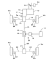
以下、本発明の実施の形態を図面に基づいて説明する。図1は、本発明の実施の形態に係る4輪駆動車のトルク配分制御装置を搭載する4輪駆動車の構成を概念的に示す図である。図1において、エンジン10の出力側にトランスアクスル11が組付けられる。トランスアクスル11は、トランスミッション12、トランスファおよびフロントディファレンシャル13を一体に備える。トランスアクスル11は、エンジン10の出力トルクを、フロントディファレンシャル13を介してフロントアクスルシャフト14に出力して駆動輪である左右の前輪Wfl,Wfrを駆動するとともに第1プロペラシャフト15に出力する。第1プロペラシャフト15は電磁クラッチ16を介して第2プロペラシャフト20に連結されている。電磁クラッチ16は、電子制御装置17により車両の走行状況に応じて演算された指令トルクに基づいて制御され、第2プロペラシャフト20を介して従動輪である後輪Wrl,Wrrに指令トルクを配分する。電流制御回路18は、制御装置17により演算された指令トルクに応じた指令電流を電磁クラッチ16の励磁コイル19に印加し、電磁クラッチ16は指令電流に応じて複数枚のクラッチ板を圧接して指令トルクを第1プロペラシャフト15から第2プロペラシャフト20にトルク伝達する。第2プロペラシャフト20に伝達されたトルクはリアディファレンシャル21に伝達され、リアディファレンシャル21からリアアクスルシャフト22に出力されて従動輪である左右の後輪Wrl,Wrrに配分される。電流制御回路18および電磁クラッチ16等により、エンジン10から駆動輪Wfl,Wfrへ伝達されるトルクを従動輪Wrl,Wrrへ配分するトルク配分装置23が構成されている。
【0019】
駆動輪Wfl,Wfrおよび従動輪Wrl,Wrrの車輪速度を検出する車輪速センサSfl,Sfr,Srl,Srrが各車輪に対応して設けられている。なお、各車輪速センサは、各車輪を制動する各車輪ブレーキBfl,Bfr,Brl,Brrを独立して制御するアンチロックブレーキシステム(ABS)用の車輪速センサを兼用する。さらに、エンジン10の吸気系のスロットルボデーには、アクセルペダルの踏込み量に応じて吸気量を調整するスロットルバルブ24のスロットル開度θを検出するスロットル開度センサSthが設けられている。トランスミッション12には、各変速段Gを成立するためにギヤチェンジを行うシフトレバーの位置を検出するギヤポジションセンサSgが設けられている。
【0020】
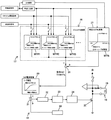
電子制御装置17は、図2に示すように、車輪速センサSfl,Sfr,Srl,Srrおよびスロットル開度センサSthに接続されるとともにトルク配分装置23の電流制御回路18に接続されている。電子制御装置17は、トルク配分装置23を制御するための各種演算処理を行うCPU25と、CPU25により実行される図6に示すトルク配分制御プログラムを予め格納したROM26と、CPU25のトルク配分制御中に随時必要なデータが読み書きされるRAM27と、車輪速センサSfl,Sfr,Srl,Srr、スロットル開度センサSthおよびギヤポジションセンサSgから車輪速信号、スロットル開度信号および変速段信号を入力するとともにCPU25による演算結果である指令電流Iを電流制御回路18に出力する入出力回路28とを含んで構成されている。
【0021】
図3に示すように、電子制御装置17は、演算した指令トルクTを電磁クラッチ16が従動輪Wrl,Wrrに伝達するために電磁コイル19に印加しなければならない指令電流Iを演算して電流制御回路18に出力する。電磁クラッチ16が伝達する指令トルクTと指令電流Iとの関係はトルク電流マップ29としてROM26に記憶され、指令トルクに対する指令電流はこのトルク電流マップ29から読み出される。なお、指令電流は指令トルクと指令電流との関係を示す計算式から求めてもよい。
【0022】
電流制御回路18は、電磁クラッチ16の電磁コイル19に流れた実電流Irを電流検出部30で検出し、電子制御装置17から入力された指令電流Iと実電流Irとの差を減算部31で演算し、PI制御部32で増幅してPWM出力変換部33でパルス幅変調した電圧を出力駆動部34からスイッチング・トランジスタ35のベースに印加している。スイッチング・トランジスタ35は電磁コイル19と直列にバッテリBに接続されているので、電磁コイル19には指令電流Iが印加される。
【0023】
電子制御装置17は、車速V、スロットル開度θおよびトランスミッション12の変速段Gに基づいて従動輪Wrl,Wrrに伝達するプレトルクTffを演算するプレトルク演算手段36と、車速Vおよび駆動輪と従動輪との回転速度差ΔNに基づいて補正トルクTfbを演算する補正トルク演算手段37と、プレトルクおよび補正トルクを加算して指令トルクTを演算する加算手段38を備えている。
【0024】
車速Vは、車輪速センサSrl,Srrにより検出された従動輪Wrl,Wrrの回転数の平均値から算出し、スロットル開度θは、スロットルセンサSthにより検出されたスロットルバルブ24の開度を全開状態に対してパーセントで表したものであり、変速段は、ギヤポジションセンサSgにより検出されたトランスミッション12のシフトレバーの位置から求めたものである。変速段Gは、車速Vとエンジン回転数から演算してもよく、或いは自動変速機付き車両の場合、自動変速機制御用のECUで演算された変速段を使用するようにしてもよい。
【0025】
プレトルク演算手段36では、車速Vおよびスロットル開度θに応じて従動輪Wrl,Wrrに伝達するプレトルクTffをトランスミッションの変速段G毎に設定した複数のプレトルクマップMTff1,MTff2,MTff3…がROM26に登録され、トルク配分制御プログラムが実行されて、変速段に対応するプレトルクマップMTffが選択され、車速Vおよびスロットル開度θからプレトルクTffが演算される。図4に示す第1速段におけるプレトルクマップMTff1においては全体の傾向として、プレトルクTffは車速Vがゼロ近傍で大であり、所定速度まで車速の増加につれて減少し、且つスロットル開度θの増加に対する増加割合は大である。車速が所定速度以上になると、プレトルクTffは小さく、スロットル開度θの増加に対する増加割合も小さい。
【0026】
同じ車速V、スロットル開度θであっても、車両の走行安定性を向上し、または燃費をよくするために、従動輪に伝達される適切なトルクは走行状況によって異なる。即ち、低速段が選択される発進時、中速段でのコーナリング時などでは、確実に4輪にトルク配分して安定性の向上を図る必要がある。逆に高速段でのクルージング走行時などでは、従動輪にあまりトルク配分する必要性がなく、従動輪へのトルク配分を下げて燃費を向上するのが望ましい。このような特性をプレトルクマップに反映するために、変速段が高くなるにつれて、車速Vが低いときのプレトルクTffは小さく、スロットル開度θの増加に対するプレトルクTff増加割合も小さく、車速が所定速度以上のプレトルクTffも小さく設定されている。このように設定されたプレトルクマップMTffが変速段毎にROM26に登録されているので、選択された変速段により示される運転者の意思をダイレクトに反映して従動輪Wrl,Wrrに適切なトルク配分を行うことができる。
【0027】
なお、プレトルクマップMTffは、変速段毎に複数個設けるのではなく、基準例えば3速段のプレトルクマップを一つ用意し、1速段では基準のプレトルクマップから求めたプレトルクTffの1.5倍、5速段では0.5倍等にするようにしてもよい。また、プレトルクTffは、プレトルクマップMTffから演算するのではなく、車速Vおよびスロットル開度θから所定の計算式により演算するようにしてもよい。
【0028】
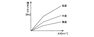
補正トルク演算手段37では、駆動輪と従動輪との回転速度差ΔNに対する補正トルクTfbが複数の車速Vをパラメータとして設定された補正トルクマップMTfbがROM26に登録され、トルク配分制御プログラムが実行されて、補正トルクマップMTfbに基づいて駆動輪と従動輪との回転速度差ΔNおよび車速Vから補正トルクTfbが演算される。図5に示す補正トルクマップMTfbにおいては全体の傾向として、駆動輪と従動輪との回転速度差ΔNがゼロのとき補正トルクTfbはゼロであり、補正トルクTfbは、回転速度差ΔNの増加に比例して一定の傾きで増加し、所定値を超えると傾きが小さくなっている。補正トルクTfbは、車速Vが低速ほど大きく、高速になるにつれて小さく設定されている。
【0029】
次に、上記実施の形態に係る4輪駆動車のトルク配分制御装置の作動を説明する。CPU25は、図6のトルク配分プログラムを微小時間間隔で実行し、先ず、車輪速センサSfl,Sfr,Srl,Srr、スロットルセンサSthおよびギヤポジションセンサSgからの各種信号を取込処理する(ステップ41)。車輪速センサSrl,Srrにより検出された従動輪Wrl,Wrrの回転数の平均値に基づいて車速Vが演算される(ステップ42)。車輪速センサSfl,Sfrにより検出された駆動輪Wfl,Wfrの回転数の平均値から従動輪Wrl,Wrrの回転数の平均値が減算されて駆動輪と従動輪との回転速度差ΔNが演算される(ステップ43)。ギヤポジションセンサSgにより検出された変速段Gに対応するプレトルクマップTMが選択され、車速VおよびスロットルセンサSthにより検出されたスロットル開度θに対応するプレトルクTffがフィードフォワード的に演算される(ステップ44)。補正トルクマップMTfbに基づいて回転速度差ΔNおよび車速Vに対応する補正トルクTfbがフィードバック的に演算される(ステップ45)。トルク演算手段38をなすステップ46において、プレトルクTffと補正トルクTfbとが加算されて指令トルクTが演算される。電磁クラッチ16が指令トルクTを伝達するために、電磁コイル19に印加しなければならない指令電流Iが、指令トルクTに対する指令電流Iを記憶したトルク電流マップ29から読み出され(ステップ47)、電流制御回路18に出力される。(ステップ48)。電流制御回路18は、指令電流Iと電磁クラッチ16の電磁コイル19に流れる実電流Irとの差を増幅してパルス幅変調し、スイッチング・トランジスタ35に出力して電磁コイル19に指令電流Iを印加する。これにより電磁クラッチ16は指令トルクTを第1プロペラシャフト15から第2プロペラシャフト20に伝達して従動輪である後輪Wrl,Wrlに配分する。
【0030】
このとき、例えば第1速段が選択されて発進する場合、第1速段に対応して選択される第1プレトルクマップTMff1では、車速Vが小さくスロットル開度θが大きいとき大きいプレトルクTff1が設定されているので、発進時に従動輪にも大きなトルクが配分されてスリップすることなく発進することができる。また、中速段で選択されるプレトルクマップTMでは、車速Vが中速のときプレトルクTffが概してスロットル開度θに拘わらず中程度に設定されているので、中速段でコーナリングする場合、従動輪に適切なトルク配分がなされ、4輪で路面を確実にグリップして安定してコーナリングすることができる。高速段で選択されるプレトルクマップTMでは、車速Vが高速のときプレトルクTffがスロットル開度θがかなり大きくても小さく設定されているので、高速段でのクルージング走行時に燃費を向上することができる。このように変速段換言すればギヤ選択という運転者の意思をダイレクトに反映したプレトルクマップMTffを変速段毎に設定し、変速段に対応するプレトルクマップMTffからプレトルクが演算されるので、各走行状況に最適なトルクを従動輪Wrl,Wrrに配分することができる。
【図面の簡単な説明】
【図1】本発明の実施形態に係る4輪駆動車のトルク配分制御装置の概念図。
【図2】電子制御装置を示すブロック図。
【図3】本発明の実施形態に係る4輪駆動車のトルク配分制御装置の各部の機能を示すブロック図。
【図4】第1速段で選択される第1プレトルクマップの一例を示す図。
【図5】補正トルクマップを示す図。
【図6】トルク配分プログラムを示す図。
【符号の説明】
10…エンジン、11…トランスアクスル、12…トランスミッション、13…フロントディファレンシャル、14…フロントアクスル、15…第1プロペラシャフト、16…電磁クラッチ、17…電子制御装置、18…電流制御回路、19…電磁コイル、20…第2プロペラシャフト、21…リアディファレンシャル、22…リアアクスル、23…トルク配分装置、29…トルク電流マップ、36…プレトルク演算手段、37…補正トルク演算手段、38…加算手段、Wfl,Wfr…前輪(駆動輪)、Wrl,Wrr…後輪(従動輪)、Sfl,Sfr,Srl,Srr…車輪速センサ、Sth…スロットル開度センサ、Sg…ギヤポジションセンサ。[0001]
TECHNICAL FIELD OF THE INVENTION
The present invention relates to a torque distribution control device that controls torque distribution to driven wheels of a four-wheel drive vehicle.
[0002]
[Prior art]
In a torque distribution control device for a four-wheel drive vehicle having a torque transmission clutch for distributing torque transmitted from an engine to a driven wheel to a driven wheel according to a rotational speed difference between the driven wheel and a driven wheel, the acceleration of the vehicle is controlled to a predetermined value. If the value is equal to or greater than the value, by selecting an acceleration mode map in which the rate of increase in the torque allocated to the driven wheels with respect to the increase in the rotational speed difference between the drive wheel and the driven wheel is increased, a large torque is provided for the rotational speed difference. If the torque is smaller than a predetermined value, the torque is distributed to the driven wheels. Japanese Patent Application Laid-Open No. 2001-71781 discloses that the wheels are distributed to driven wheels.
[0003]
[Patent Document 1]
JP 2001-71781 A (pages 4, 5; FIG. 3)
[0004]
[Problems to be solved by the invention]
According to the above-mentioned conventional method, stable acceleration and starting can be performed by distributing a large torque to driven wheels when accelerating or starting on a low μ road, and distributed to driven wheels during tight corner turning at low speed. Tight corner braking can be avoided by reducing the torque. However, merely determining whether or not the acceleration of the vehicle is equal to or higher than a predetermined value, for example, when cornering at a medium speed where the acceleration is equal to or lower than the predetermined value, distributes the torque necessary for improving stability to the driven wheels. I can't. As described above, according to the conventional method, it is not possible to sufficiently grasp the traveling state, and it is not possible to directly reflect the traveling state of the vehicle or the driver's intention to distribute the torque to the driven wheels.
[0005]
SUMMARY OF THE INVENTION The present invention has been made to solve the above-described problem, and it is an object of the present invention to improve the stability and reduce the fuel consumption by appropriately distributing the torque to the four wheels according to the driving situation.
[0006]
[Means for Solving the Problems]
In order to solve the above-mentioned problem, a structural feature of the invention according to
[0007]
According to a second aspect of the present invention, in the first aspect, the correction torque calculating means calculates the correction torque based on a rotational speed difference between a driving wheel and a driven wheel and a vehicle speed.
[0008]
According to a third aspect of the present invention, in the first or second aspect, the pre-torque calculating means includes a pre-torque map in which a pre-torque transmitted to a driven wheel is set according to a vehicle speed and a throttle opening. A plurality of pre-torque maps are provided for each shift speed, and a pre-torque map corresponding to the selected shift speed is selected to calculate the pre-torque.
[0009]
According to a fourth aspect of the present invention, in the first or second aspect, the pre-torque calculation means includes a pre-torque map in which a pre-torque transmitted to a driven wheel is set according to a vehicle speed and a throttle opening. At least one gear position is provided, and a pre-torque obtained from the pre-torque map according to the vehicle speed and the throttle opening is corrected and calculated according to the difference between the one gear position and the selected gear position.
[0010]
According to a fifth aspect of the present invention, in any one of the first to fourth aspects, the pre-torque calculating means detects a vehicle speed calculated from a wheel speed detected by a wheel speed sensor and a vehicle speed detected by a throttle sensor. The pre-torque transmitted to the driven wheels is calculated based on the throttle opening and the gear position detected by the gear position sensor.
[0011]
A structural feature of the invention according to claim 6 is that, in any one of
[0012]
Function and Effect of the Invention
In the invention according to
[0013]
In the invention according to claim 2 configured as described above, the correction torque is calculated in a feedback manner based on the rotational speed difference between the drive wheel and the driven wheel and the vehicle speed. It is possible to distribute the torque to the driven wheels reflecting the driver's intention.
[0014]
In the invention according to
[0015]
In the invention according to claim 4 configured as described above, a pre-torque map in which the pre-torque transmitted to the driven wheels is set according to the vehicle speed and the throttle opening is provided corresponding to at least one shift speed of the transmission. A pre-torque is obtained from the pre-torque map according to the vehicle speed and the throttle opening, and the pre-torque is corrected and calculated according to the difference between the selected shift speed and one shift speed. Thus, in addition to the effect of the first aspect, an appropriate torque can be distributed to the driven wheels based on one pretorque map by directly reflecting the driver's intention indicated by the gear position. .
[0016]
In the invention according to claim 5 configured as described above, the vehicle speed calculated from the wheel speed of the driven wheel detected by the wheel speed sensor, the throttle opening detected by the throttle sensor, and the vehicle speed calculated by the gear position sensor Since the pre-torque to be transmitted to the driven wheels is calculated based on the gear position, the driving condition can be reliably detected by each sensor, and the torque suitable for the driving condition can be distributed to the driven wheels.
[0017]
In the invention according to claim 6 configured as described above, by applying the command current to the electromagnetic coil, the electromagnetic clutch transmits the command torque according to the traveling condition to the driven wheels, so that a proper configuration can be achieved with a simple configuration. The torque can be transmitted to the driven wheels to improve stability and fuel efficiency.
[0018]
BEST MODE FOR CARRYING OUT THE INVENTION
Hereinafter, embodiments of the present invention will be described with reference to the drawings. FIG. 1 is a diagram conceptually showing a configuration of a four-wheel drive vehicle equipped with a four-wheel drive vehicle torque distribution control device according to an embodiment of the present invention. In FIG. 1, a
[0019]
Wheel speed sensors Sfl, Sfr, Srl, Srr for detecting the wheel speeds of the drive wheels Wfl, Wfr and the driven wheels Wrl, Wrr are provided for each wheel. Each wheel speed sensor also serves as a wheel speed sensor for an antilock brake system (ABS) that independently controls each wheel brake Bfl, Bfr, Brl, Brr that brakes each wheel. Further, the throttle body of the intake system of the
[0020]
As shown in FIG. 2, the
[0021]
As shown in FIG. 3, the
[0022]
The
[0023]
The
[0024]
The vehicle speed V is calculated from the average value of the rotation speeds of the driven wheels Wrl and Wrr detected by the wheel speed sensors Srl and Srr, and the throttle opening θ is obtained by fully opening the
[0025]
The pre-torque calculating means 36 stores in the ROM 26 a plurality of pre-torque maps MTff1, MTff2, MTff3... In which pre-torques Tff transmitted to the driven wheels Wrl and Wrr are set for each transmission speed G according to the vehicle speed V and the throttle opening θ. The pre-torque map MTff corresponding to the shift speed is selected by executing the registered torque distribution control program, and the pre-torque Tff is calculated from the vehicle speed V and the throttle opening θ. In the pre-torque map MTff1 at the first speed shown in FIG. 4, as a whole tendency, the pre-torque Tff is large near the vehicle speed V of zero, decreases as the vehicle speed increases to a predetermined speed, and increases the throttle opening θ. The rate of increase is large. When the vehicle speed becomes equal to or higher than the predetermined speed, the pre-torque Tff is small, and the rate of increase with the increase in the throttle opening θ is small.
[0026]
Even at the same vehicle speed V and the same throttle opening θ, the appropriate torque transmitted to the driven wheels varies depending on the driving conditions in order to improve the running stability of the vehicle or improve the fuel efficiency. That is, at the time of starting when the low gear is selected, at the time of cornering at the medium gear, and the like, it is necessary to surely distribute torque to the four wheels to improve stability. Conversely, when cruising at a high speed, for example, it is not necessary to distribute much torque to the driven wheels, and it is desirable to reduce the torque distribution to the driven wheels to improve fuel efficiency. In order to reflect such characteristics in the pre-torque map, as the shift speed increases, the pre-torque Tff when the vehicle speed V is low is small, the increasing rate of the pre-torque Tff with respect to the increase in the throttle opening θ is small, and the vehicle speed is a predetermined speed. The above pre-torque Tff is also set small. Since the pre-torque map MTff set in this manner is registered in the
[0027]
It should be noted that a plurality of pretorque maps MTff are not provided for each shift speed, but a reference, for example, one pretorque map for the third speed is prepared, and for the first speed, one pretorque Tff obtained from the reference pretorque map is used. The speed may be 0.5 times or 0.5 times at the 5th speed. Further, the pre-torque Tff may be calculated from the vehicle speed V and the throttle opening θ by a predetermined formula, instead of being calculated from the pre-torque map MTff.
[0028]
In the correction torque calculating means 37, a correction torque map MTfb in which the correction torque Tfb for the rotational speed difference ΔN between the driving wheel and the driven wheel is set using a plurality of vehicle speeds V as parameters is registered in the
[0029]
Next, the operation of the torque distribution control device for a four-wheel drive vehicle according to the above embodiment will be described. The
[0030]
At this time, for example, when the first speed is selected and the vehicle starts, the first pre-torque map TMff1 selected corresponding to the first speed shows a large pre-torque Tff1 when the vehicle speed V is small and the throttle opening θ is large. Since it is set, a large torque is also distributed to the driven wheels at the time of starting, and the vehicle can start without slipping. In the pre-torque map TM selected at the middle speed, the pre-torque Tff is generally set to a medium level when the vehicle speed V is the middle speed regardless of the throttle opening θ. Appropriate torque distribution is performed on the driven wheels, and the four wheels can reliably grip the road surface and perform stable cornering. In the pre-torque map TM selected at the high speed stage, when the vehicle speed V is high, the pre-torque Tff is set to be small even if the throttle opening θ is considerably large, so that it is possible to improve fuel efficiency during cruising traveling at the high speed stage. it can. In this way, in other words, the pre-torque map MTff that directly reflects the driver's intention to select the gear is set for each gear, and the pre-torque is calculated from the pre-torque map MTff corresponding to the gear. It is possible to distribute the torque optimal for the driving situation to the driven wheels Wrl and Wrr.
[Brief description of the drawings]
FIG. 1 is a conceptual diagram of a torque distribution control device for a four-wheel drive vehicle according to an embodiment of the present invention.
FIG. 2 is a block diagram showing an electronic control device.
FIG. 3 is a block diagram showing functions of each unit of the torque distribution control device for a four-wheel drive vehicle according to the embodiment of the present invention.
FIG. 4 is a diagram showing an example of a first pretorque map selected at a first speed.
FIG. 5 is a view showing a correction torque map.
FIG. 6 is a diagram showing a torque distribution program.
[Explanation of symbols]
DESCRIPTION OF
Claims (6)
Priority Applications (3)
| Application Number | Priority Date | Filing Date | Title |
|---|---|---|---|
| JP2002318494A JP2004149054A (en) | 2002-10-31 | 2002-10-31 | Torque distribution control device for four-wheel drive vehicle |
| US10/695,991 US6945909B2 (en) | 2002-10-31 | 2003-10-30 | Torque distribution control device for four-wheel drive vehicle |
| EP03024807A EP1415850A3 (en) | 2002-10-31 | 2003-10-30 | Torque distribution control device for four-wheel drive vehicle |
Applications Claiming Priority (1)
| Application Number | Priority Date | Filing Date | Title |
|---|---|---|---|
| JP2002318494A JP2004149054A (en) | 2002-10-31 | 2002-10-31 | Torque distribution control device for four-wheel drive vehicle |
Publications (1)
| Publication Number | Publication Date |
|---|---|
| JP2004149054A true JP2004149054A (en) | 2004-05-27 |
Family
ID=32461616
Family Applications (1)
| Application Number | Title | Priority Date | Filing Date |
|---|---|---|---|
| JP2002318494A Pending JP2004149054A (en) | 2002-10-31 | 2002-10-31 | Torque distribution control device for four-wheel drive vehicle |
Country Status (1)
| Country | Link |
|---|---|
| JP (1) | JP2004149054A (en) |
Cited By (1)
| Publication number | Priority date | Publication date | Assignee | Title |
|---|---|---|---|---|
| JP2011031829A (en) * | 2009-08-05 | 2011-02-17 | Honda Motor Co Ltd | Torque distribution control device of four-wheel drive vehicle |
-
2002
- 2002-10-31 JP JP2002318494A patent/JP2004149054A/en active Pending
Cited By (2)
| Publication number | Priority date | Publication date | Assignee | Title |
|---|---|---|---|---|
| JP2011031829A (en) * | 2009-08-05 | 2011-02-17 | Honda Motor Co Ltd | Torque distribution control device of four-wheel drive vehicle |
| CN101992690A (en) * | 2009-08-05 | 2011-03-30 | 本田技研工业株式会社 | Torque distribution control device for four-wheel drive vehicle |
Similar Documents
| Publication | Publication Date | Title |
|---|---|---|
| JP4456748B2 (en) | Power distribution control device for four-wheel drive vehicles | |
| JP3585798B2 (en) | Driving force control device for four-wheel drive vehicle | |
| US6704627B2 (en) | Drive force distribution apparatus for hybrid vehicle | |
| JP2914040B2 (en) | Driving force distribution control device for four-wheel drive vehicle | |
| JP4192631B2 (en) | Torque distribution control device for four-wheel drive vehicles | |
| JPH02270641A (en) | Drive force distribution controller for four-wheel drive vehicle | |
| JPH0729557B2 (en) | Drive force distribution controller for four-wheel drive vehicle | |
| CN101362437A (en) | Driving force distribution control method and device for four wheel drive vehicle | |
| US6945909B2 (en) | Torque distribution control device for four-wheel drive vehicle | |
| JP2002234355A (en) | Control device for four-wheel drive vehicle | |
| JP2001287561A (en) | Driving force control device for four-wheel drive vehicle | |
| EP1400390A2 (en) | Power distribution control apparatus for four wheel drive vehicle | |
| JP2583910B2 (en) | Driving force distribution control method for front and rear wheel drive vehicles | |
| JP2001163209A (en) | Torque variable distribution control system of four- wheel drive car | |
| JP2004149054A (en) | Torque distribution control device for four-wheel drive vehicle | |
| JP2006177166A (en) | Traction control device | |
| JP2004231004A (en) | Wheel state estimating device for vehicle | |
| US6688415B2 (en) | Stability control throttle compensation on vehicles with passive all wheel drive systems | |
| JP3410514B2 (en) | Differential limit controller | |
| JP3412313B2 (en) | Driving force distribution control device for four-wheel drive vehicle | |
| JP3325345B2 (en) | Driving force control device for four-wheel drive vehicle | |
| JP2004149055A (en) | Torque distribution control device for four-wheel drive vehicle | |
| JP2006528573A (en) | Control device for a motor vehicle driven at least part-time in four wheels | |
| JPH0717282A (en) | Driving force control device for four-wheel drive vehicle | |
| JP3397844B2 (en) | Vehicle differential limiting control device |
Legal Events
| Date | Code | Title | Description |
|---|---|---|---|
| A621 | Written request for application examination |
Free format text: JAPANESE INTERMEDIATE CODE: A621 Effective date: 20050318 |
|
| A711 | Notification of change in applicant |
Free format text: JAPANESE INTERMEDIATE CODE: A712 Effective date: 20060301 |
|
| A977 | Report on retrieval |
Free format text: JAPANESE INTERMEDIATE CODE: A971007 Effective date: 20070711 |
|
| A131 | Notification of reasons for refusal |
Free format text: JAPANESE INTERMEDIATE CODE: A131 Effective date: 20071016 |
|
| A521 | Written amendment |
Free format text: JAPANESE INTERMEDIATE CODE: A523 Effective date: 20071207 |
|
| A131 | Notification of reasons for refusal |
Free format text: JAPANESE INTERMEDIATE CODE: A131 Effective date: 20080422 |
|
| A02 | Decision of refusal |
Free format text: JAPANESE INTERMEDIATE CODE: A02 Effective date: 20080826 |