【0001】
【発明の属する技術分野】
本発明は、シンク本体内の水に浸漬された食器を超音波洗浄する超音波洗浄シンクに関するものである。
【0002】
【従来の技術】
従来より、食器の汚れを超音波で落とす超音波洗浄装置が利用されている。これは、食器を超音波洗浄装置の洗浄ケーシング内に入れて水を満たし、超音波発生器で超音波を発生して食器の汚れを落とすものである。
【0003】
ところで最近では、種々のユニットを一まとめにしてシステム化したいわゆるシステムキッチンが良く利用されているが、超音波洗浄装置を組み込んだものは少なく、このため、超音波洗浄装置をシステムに組み込んだものが考えられている。この場合、単体の超音波洗浄装置を外付けするのではなくシンク本体に超音波発生器を組み込んで構成してある(例えば特許文献1参照)。
【0004】
このような超音波発生器を組み込んだシンクにあっては、シンク本体内に貯留した水に食器を浸漬し、前記食器にシンク本体内の水を介して超音波を当てて食器に付着した汚れを食器から剥離して除去するものである。
【0005】
しかしながら、このような従来の超音波洗浄シンクにあっては、シンク本体内の水に浸漬された食器に超音波を当てて付着した汚れを除去するのであるが、超音波洗浄中は食器が浸漬されている水はシンク本体内に留められているため、食器から除去された汚れは超音波による洗浄が終わるまで水中を浮遊することとなり、汚れが浮遊した水の中に食器が浸漬された状態で超音波洗浄を行っていて汚れが除去されにくいものであった。
【0006】
【特許文献1】
実開平7−33137号公報
【0007】
【発明が解決しようとする課題】
本発明は上記の点に鑑みて発明したものであって、その目的とするところは、食器から除去された汚れが水中を浮遊したままとならないように汚れを回収することができる超音波洗浄シンクを提供することを課題とするものである。
【0008】
【課題を解決するための手段】
上記課題を解決するために本発明の超音波洗浄シンクにあっては、内部に水11が貯留されて前記水11に食器12が浸漬されるシンク本体1と、シンク本体1内の食器12を超音波洗浄する超音波発生ユニット2と、シンク本体1内の水11を吸い出して濾過した後再びシンク本体1内に戻すための途中にポンプ33及び濾過器34を設けた循環配管3とで構成されて成ることを特徴とするものである。このような構成とすることで、超音波洗浄中に食器12から除去された汚れが食器12が浸漬されている水11の中を浮遊したままとならないよう回収することができて、汚れをあまり含まない水11にて超音波洗浄ができて食器12の汚れを良く除去することができる。
【0009】
【発明の実施の形態】
本発明を添付図面に示す実施形態に基づいて説明する。図1に本実施形態の概略構成を示す。
【0010】
シンク本体1は、上方に開口して内部に水11を貯留可能に形成してあり、この水11に洗浄対象となる食器12を浸漬する。食器12は、食材を盛る器だけでなく、湯のみやグラス、箸やスプーン、鍋やフライパン、包丁やまな板等、キッチンで料理に用いる用具等も含まれる。シンク内部に水11を注ぎ込むための給水口42がシンク本体1に設けてあると共に、水道4から前記給水口42までの配管途中に給水バルブ41が設けてあり、この給水バルブ41は後述する制御部8にて制御される。
【0011】
シンク本体1の底部には、シンク本体1内部の水11を排水するための排水口5が形成してある。排水口5には、途中に排水トラップ53を設けた排水管52が接続してあり、排水口5近傍の排水管52の途中には排水バルブ51が設けてある。
【0012】
また、シンク本体1の上端部近傍には、オーバーフロー部6の吸込口31が設けてあり、このオーバーフロー管61の下流側は上述した排水管52の排水トラップ53のすぐ上流部分に接続してある。これにより、オーバーフロー部6の吸込口31より上方に越える水11についてはオーバーフロー部6から排水され、シンク本体1の上端部から水11が溢れ出るのを防止することができる。
【0013】
そしてシンク本体1には、超音波発生ユニット2が設けられる。超音波発生ユニット2は、シンク本体1の内壁に形成される超音波振動子21と、超音波振動子21を振動させるための超音波ユニット本体22とからなる。超音波振動子21は、シンク本体1の内壁、即ち、オーバーフロー部6の吸込口31からより下方の側壁、及びシンク本体1の底面等に形成されるもので、シンク本体1の内部に貯留された水11に超音波を流すものである。また、超音波ユニット本体22は、超音波振動子21と制御部8とにそれぞれ接続されて制御部8からの制御指令を受けて超音波振動子21を駆動するものである。
【0014】
またシンク本体1には、循環配管3が設けてある。循環配管3は、シンク本体1からの吸込口31,シンク本体1への吐出口35に至る経路の途中に上流側より順にフィルタ32,ポンプ33,濾過器34を設けてある。この循環配管3のポンプ33は制御部8に接続される。
【0015】
更に本実施形態では、シンク本体1に乾燥ユニット7を設けてある。これは、シンク本体1のオーバーフロー部6の吸込口31よりも上方の側壁に吐気口70を形成し、この吐気口70から乾燥した温風を吐出可能なようにファン及びヒータを備えた除湿装置を設けたもので、洗浄後に食器12の乾燥を行うものである。
【0016】
このような超音波洗浄シンクの動作について説明する。
【0017】
まず、シンク本体1内を予めすすぎ等により洗浄しておき、排水バルブ51を閉じて排水口5を閉塞すると共に、循環配管3のポンプ33及び乾燥ユニット7を停止しておく。そして、給水バルブ41を開いて水道水11を給水口42からシンク本体1内に注ぎ込み、適当量の水11をシンク本体1内に貯留する。水11の量は食器12の数量,嵩によって適宜決定される。そして、シンク本体1内に貯留された水11に使用後の上述した食器12を浸漬していく。なお、先に食器12をシンク本体1内に載置し、その後でシンク本体1内に水11を注ぎ込んで貯留してもよい。本実施形態では制御部8によって給水バルブ41及び排水バルブ51,超音波ユニット本体22,循環配管3のポンプ33,乾燥ユニット7を制御するようにしているが、これらは手動でスイッチを入切りして駆動・停止を行うようにしてもよい。
【0018】
次に、超音波発生ユニット2を駆動して超音波振動子21を振動させると共に、循環配管3のポンプ33を作動して超音波洗浄を行う。超音波振動子21は、制御部8からの駆動指令を超音波ユニット本体22が受けて駆動され、水11に超音波が流される。これにより、水11の中に浸漬している食器12及び該食器12に付着した汚れに超音波が当たって振動し、汚れが食器12から剥離される。剥離した汚れは、水11と共に循環配管3のポンプ33に引かれて吸込口31から吸引され、まずフィルタ32で水11に溶けないごみや固形物が除去され、その後濾過器34で汚れ成分が濾過されて浄化された水11が吐出口35から再びシンク本体1内へと戻るものである。なお、水11面がオーバーフロー部6の吸込口31よりも上方に位置するような場合には該吸込口31より水11がオーバーフロー部6に流れ込み、排水管52より排水されるもので、水11がシンク本体1の上端部から溢れ出ることはないものである。
【0019】
そして、食器12から汚れが充分に除去されると、超音波発生ユニット2及び循環配管3のポンプ33を停止して超音波洗浄を終了し、排水バルブ51を開いてシンク本体1内の水11の排水を行う。この後、後述する乾燥動作に移行してもよいが、通常は、排水バルブ51を閉じると共に、給水バルブ41を開いて水11をシンク本体1内に注ぎ込んで貯留し、すすぎを行う。そしてすすぎを行った後、排水バルブ51を開いてシンク本体1内の水11の排水を行う。排水管52には排水トラップ53を設けてあるので、下流側からの臭気が配水口やオーバーフロー部6より室内に逆流するのが阻止される。
【0020】
次に、乾燥ユニット7を駆動して乾燥動作を行う。乾燥ユニット7のファン及びヒータを駆動して除湿された温風をシンク本体1の側壁に設けた吐気口70から吐出し、超音波洗浄及びすすぎを行った食器12を乾燥させるものである。
【0021】
以上のような構成によれば、シンク本体1に超音波振動子21を設けた超音波洗浄シンクにおいて、途中に濾過器34及びポンプ33を設けた循環配管3を設けてシンク本体1内の水11を濾過するようにしたので、超音波洗浄中に食器12から剥離除去された汚れが水11中に浮遊したままとなるのを防止してシンク本体1内の水11を浄化することが可能となり、超音波洗浄にて食器12の汚れを一層良く除去することが可能となるものである。
【0022】
次に、以上のような超音波洗浄シンクを組み込んだシステムキッチンカウンターの実施例について説明する。
[実施例1]
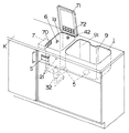
図2に本実施例の斜視図を示す。本実施例においては、カウンターKの上面の一部にシンクを形成し、超音波発生ユニット2や乾燥ユニット7等の上述した構成要素はカウンターK内に配設してある。
【0023】
本実施例では、シンク本体1の内部を上述した超音波洗浄を行う超音波洗浄専用シンク1aと、超音波洗浄を行うことができない通常のシンク9とに仕切って形成してある。なお、超音波洗浄専用シンク1aと通常のシンク9を仕切る仕切り91は、その上端部がシンク本体1の上端部よりも若干下方に位置しており、上端部においてこれら超音波洗浄専用シンク1a内部と通常のシンク9内部とは連通している。
【0024】
そして、超音波洗浄専用シンク1aには、その上開口を閉塞する外蓋71が開閉自在に設けてある。この外蓋71は、超音波洗浄や給排水11の際に水11や汚れ等が飛散しないようにするため、及び、乾燥を行う際に超音波洗浄専用シンク1a内を略密閉した状態として乾燥効率を向上させるために設けてある。そして、乾燥時には、乾燥した温風が吐気口70から超音波洗浄専用シンク1a内に吐出されるのであるが、仕切り91の上端部と外蓋71との間の隙間から通常のシンク9へと流出することができる。本実施例では、仕切り91の上端部をシンク本体1の上端部より若干下げて形成してあるので、超音波洗浄専用シンク1aにオーバーフロー部6を設けなくとも、仕切り91の上端部を越える水11については仕切りの上端部より通常のシンク9に流れ込むため、シンク本体1の上端部から水11が溢れ出ることがない。
【0025】
また、カウンターの前面には、制御部8(図示せず)に接続される操作盤Sが設けてあり、本実施形態における種々の動作をスイッチ操作により行うことができる。
【0026】
このように、超音波洗浄専用シンク1aと通常のシンク9とに分けてあるので、超音波洗浄専用シンク1aにて超音波洗浄を行っている間でも通常のシンク9を使用することが可能となる。
[実施例2]
図3に実施例2の斜視図を示す。本実施例2は上述した実施例1と大体において同じであり、異なる部分についてのみ説明する。
【0027】
本実施例では、超音波洗浄専用シンク1aと通常のシンク9とに仕切る仕切り91の上端部をシンク本体1の上端部に合わせ、超音波洗浄専用シンク1a内部と通常のシンク9内部とが連通しないようにしてある。
【0028】
そして、超音波洗浄専用シンク1aの上開口を閉塞する外蓋71には、吐気口70から超音波洗浄専用シンク1a内に吐出される乾燥した温風が逃げる開口72を形成してあり、この開口72より吐出口35から吐出された温風が外部に逃げるようになっている。
【0029】
また、本実施例では超音波洗浄専用シンク1aにオーバーフロー部6を設けてある。
【0030】
本実施例においても超音波洗浄専用シンク1aと通常のシンク9とに分けてあるので、超音波洗浄専用シンク1aにて超音波洗浄を行っている間でも通常のシンク9を使用することが可能となる。
【0031】
【発明の効果】
上述のように請求項1記載の発明にあっては、内部に水が貯留されて前記水に食器が浸漬されるシンク本体と、シンク本体内の食器を超音波洗浄する超音波発生ユニットと、シンク本体内の水を吸い出して濾過した後再びシンク本体内に戻すための途中にポンプ及び濾過器を設けた循環配管とで構成したので、超音波洗浄中に食器から除去された汚れが食器が浸漬されている水の中を浮遊したままとならないよう回収することができて、汚れをあまり含まない水にて超音波洗浄ができて食器の汚れを良く除去することができる。
【図面の簡単な説明】
【図1】本発明の一実施形態の概略構成図である。
【図2】同上における一実施例の斜視図である。
【図3】同上における他の実施例の斜視図である。
【符号の説明】
1 シンク本体
11 水
12 食器
2 超音波発生ユニット
3 循環配管
33 ポンプ
34 濾過器[0001]
TECHNICAL FIELD OF THE INVENTION
The present invention relates to an ultrasonic cleaning sink for ultrasonically cleaning tableware immersed in water in a sink body.
[0002]
[Prior art]
2. Description of the Related Art Conventionally, an ultrasonic cleaning device that removes dirt from tableware with ultrasonic waves has been used. In this method, tableware is placed in a cleaning casing of an ultrasonic cleaning apparatus and filled with water, and ultrasonic waves are generated by an ultrasonic generator to remove stains on the tableware.
[0003]
By the way, recently, the so-called system kitchen, which integrates various units into a system, is often used. However, few units incorporate an ultrasonic cleaning device, and therefore, those that incorporate an ultrasonic cleaning device into the system. Is considered. In this case, a single ultrasonic cleaning device is not externally attached, but an ultrasonic generator is incorporated in a sink body (for example, see Patent Document 1).
[0004]
In a sink incorporating such an ultrasonic generator, the tableware is immersed in water stored in the sink body, and the dirt attached to the tableware by applying ultrasonic waves to the tableware through the water in the sink body. Is peeled off from the tableware and removed.
[0005]
However, in such conventional ultrasonic cleaning sinks, ultrasonic waves are applied to tableware immersed in water in the sink body to remove dirt attached thereto, but the tableware is immersed during ultrasonic cleaning. The dirt removed from the tableware will float in the water until the ultrasonic cleaning is completed because the water that has been removed is retained in the sink body, and the tableware is immersed in the water in which the dirt is floating. And ultrasonic cleaning was performed, so that dirt was not easily removed.
[0006]
[Patent Document 1]
Published Japanese Utility Model Application No. 7-33137
[Problems to be solved by the invention]
The present invention has been made in view of the above points, and an object of the present invention is to provide an ultrasonic cleaning sink capable of collecting dirt so that dirt removed from tableware does not remain floating in water. It is an object to provide
[0008]
[Means for Solving the Problems]
In order to solve the above problem, in the ultrasonic cleaning sink of the present invention, a sink body 1 in which water 11 is stored and a tableware 12 is immersed in the water 11, and a tableware 12 in the sink body 1 are provided. An ultrasonic generating unit 2 for ultrasonic cleaning, and a circulation pipe 3 provided with a pump 33 and a filter 34 in the middle for sucking and filtering water 11 in the sink main body 1 and returning the same to the sink main body 1 again. It is characterized by being formed. With such a configuration, the dirt removed from the tableware 12 during the ultrasonic cleaning can be collected so as not to remain floating in the water 11 in which the tableware 12 is immersed. Ultrasonic cleaning can be performed with the water 11 that does not contain, and the dirt on the tableware 12 can be removed well.
[0009]
BEST MODE FOR CARRYING OUT THE INVENTION
The present invention will be described based on an embodiment shown in the accompanying drawings. FIG. 1 shows a schematic configuration of the present embodiment.
[0010]
The sink main body 1 is formed so as to open upward and store water 11 therein, and the tableware 12 to be washed is immersed in the water 11. The tableware 12 includes not only a dish for serving ingredients but also utensils used for cooking in a kitchen, such as hot water only, glass, chopsticks, spoons, pots, frying pans, kitchen knives and cutting boards. A water supply port 42 for pouring water 11 into the sink is provided in the sink body 1, and a water supply valve 41 is provided in the middle of the pipe from the water supply 4 to the water supply port 42. Controlled by the unit 8.
[0011]
A drain port 5 for draining water 11 inside the sink body 1 is formed at the bottom of the sink body 1. A drain pipe 52 provided with a drain trap 53 on the way is connected to the drain port 5, and a drain valve 51 is provided on the way of the drain pipe 52 near the drain port 5.
[0012]
A suction port 31 of the overflow section 6 is provided near the upper end of the sink body 1, and the downstream side of the overflow pipe 61 is connected to the above-mentioned drain pipe 52 immediately upstream of the drain trap 53. . As a result, the water 11 that passes above the suction port 31 of the overflow part 6 is drained from the overflow part 6, and the water 11 can be prevented from overflowing from the upper end of the sink body 1.
[0013]
The ultrasonic wave generating unit 2 is provided on the sink body 1. The ultrasonic generating unit 2 includes an ultrasonic vibrator 21 formed on the inner wall of the sink main body 1 and an ultrasonic unit main body 22 for vibrating the ultrasonic vibrator 21. The ultrasonic vibrator 21 is formed on the inner wall of the sink body 1, that is, on the side wall lower than the suction port 31 of the overflow portion 6, the bottom surface of the sink body 1, and the like, and is stored inside the sink body 1. An ultrasonic wave is caused to flow through the water 11. The ultrasonic unit main body 22 is connected to the ultrasonic vibrator 21 and the control unit 8, respectively, and drives the ultrasonic vibrator 21 in response to a control command from the control unit 8.
[0014]
Further, a circulation pipe 3 is provided in the sink body 1. The circulation pipe 3 is provided with a filter 32, a pump 33, and a filter 34 in the order from the upstream side in the middle of the path leading to the suction port 31 from the sink body 1 and the discharge port 35 to the sink body 1. The pump 33 of the circulation pipe 3 is connected to the control unit 8.
[0015]
Further, in the present embodiment, a drying unit 7 is provided in the sink body 1. This is a dehumidifier having a fan and a heater that forms an air outlet 70 on a side wall above the suction port 31 of the overflow part 6 of the sink body 1 and that can discharge dry warm air from the air outlet 70. The tableware 12 is dried after washing.
[0016]
The operation of such an ultrasonic cleaning sink will be described.
[0017]
First, the inside of the sink body 1 is rinsed in advance by rinsing or the like, the drain valve 51 is closed to close the drain port 5, and the pump 33 and the drying unit 7 of the circulation pipe 3 are stopped. Then, the water supply valve 41 is opened, the tap water 11 is poured into the sink body 1 from the water supply port 42, and an appropriate amount of the water 11 is stored in the sink body 1. The amount of water 11 is appropriately determined according to the quantity and bulk of tableware 12. Then, the used tableware 12 described above is immersed in the water 11 stored in the sink body 1. The tableware 12 may be placed in the sink body 1 first, and then the water 11 may be poured into the sink body 1 and stored. In the present embodiment, the control unit 8 controls the water supply valve 41 and the drain valve 51, the ultrasonic unit body 22, the pump 33 of the circulation pipe 3, and the drying unit 7, but these are manually turned on and off. Driving and stopping may be performed.
[0018]
Next, the ultrasonic generating unit 2 is driven to vibrate the ultrasonic vibrator 21, and the pump 33 of the circulation pipe 3 is operated to perform ultrasonic cleaning. The ultrasonic vibrator 21 is driven by the ultrasonic unit main body 22 receiving a drive command from the control unit 8, and an ultrasonic wave flows through the water 11. Thereby, the ultrasonic wave is applied to the tableware 12 immersed in the water 11 and the dirt attached to the tableware 12 and vibrates, and the dirt is separated from the tableware 12. The peeled dirt is drawn by the pump 33 of the circulation pipe 3 together with the water 11 and is sucked from the suction port 31. First, dirt and solids insoluble in the water 11 are removed by the filter 32. The water 11 that has been filtered and purified returns from the discharge port 35 to the inside of the sink body 1 again. When the surface of the water 11 is located above the suction port 31 of the overflow section 6, the water 11 flows into the overflow section 6 from the suction port 31 and is drained from the drain pipe 52. Does not overflow from the upper end of the sink body 1.
[0019]
Then, when the dirt is sufficiently removed from the tableware 12, the ultrasonic generation unit 2 and the pump 33 of the circulation pipe 3 are stopped to terminate the ultrasonic cleaning, and the drain valve 51 is opened to open the water 11 in the sink main body 1. Drain the water. Thereafter, the operation may be shifted to a drying operation to be described later, but usually, the drain valve 51 is closed, the water supply valve 41 is opened, and the water 11 is poured into the sink body 1 to be stored and rinsed. After rinsing, the drain valve 51 is opened to drain the water 11 in the sink body 1. Since the drain pipe 52 is provided with the drain trap 53, odor from the downstream side is prevented from flowing back into the room from the water distribution port and the overflow section 6.
[0020]
Next, the drying unit 7 is driven to perform a drying operation. The fan and heater of the drying unit 7 are driven to discharge the dehumidified warm air from the air outlet 70 provided on the side wall of the sink body 1 to dry the tableware 12 which has been subjected to ultrasonic cleaning and rinsing.
[0021]
According to the above-described configuration, in the ultrasonic cleaning sink in which the ultrasonic oscillator 21 is provided in the sink body 1, the circulation pipe 3 in which the filter 34 and the pump 33 are provided is provided in the middle, and the water in the sink body 1 is provided. Since the filter 11 is filtered, it is possible to prevent the dirt separated and removed from the tableware 12 from being left floating in the water 11 during the ultrasonic cleaning and to purify the water 11 in the sink body 1. Thus, the stains on the tableware 12 can be more effectively removed by ultrasonic cleaning.
[0022]
Next, an embodiment of a system kitchen counter incorporating the above-described ultrasonic cleaning sink will be described.
[Example 1]
FIG. 2 shows a perspective view of this embodiment. In this embodiment, a sink is formed on a part of the upper surface of the counter K, and the above-described components such as the ultrasonic wave generating unit 2 and the drying unit 7 are disposed in the counter K.
[0023]
In this embodiment, the inside of the sink body 1 is formed into a sink 1a dedicated to ultrasonic cleaning for performing the above-described ultrasonic cleaning and a normal sink 9 that cannot perform ultrasonic cleaning. The upper end of the partition 91 for separating the ultrasonic cleaning sink 1a from the normal sink 9 is located slightly below the upper end of the sink body 1, and the upper end of the partition 91 is inside the ultrasonic cleaning sink 1a. And the inside of the normal sink 9 communicate with each other.
[0024]
An outer lid 71 for closing the upper opening is provided on the sink for exclusive use of ultrasonic cleaning 1a so as to be freely opened and closed. The outer lid 71 is used to prevent the water 11 and dirt from being scattered during the ultrasonic cleaning and the water supply / drainage 11 and to make the inside of the ultrasonic cleaning sink 1a substantially closed when performing the drying. It is provided to improve. Then, at the time of drying, the dried warm air is discharged from the air outlet 70 into the ultrasonic cleaning sink 1 a. The air flows from the gap between the upper end of the partition 91 and the outer lid 71 to the normal sink 9. Can spill. In the present embodiment, since the upper end of the partition 91 is formed slightly lower than the upper end of the sink main body 1, the water exceeding the upper end of the partition 91 can be provided without providing the overflow section 6 in the ultrasonic cleaning sink 1 a. Since the water 11 flows into the normal sink 9 from the upper end of the partition, the water 11 does not overflow from the upper end of the sink body 1.
[0025]
An operation panel S connected to the control unit 8 (not shown) is provided on the front surface of the counter, and various operations in the present embodiment can be performed by operating switches.
[0026]
As described above, since the ultrasonic cleaning dedicated sink 1a and the normal sink 9 are divided, it is possible to use the normal sink 9 even while performing the ultrasonic cleaning in the ultrasonic cleaning dedicated sink 1a. Become.
[Example 2]
FIG. 3 shows a perspective view of the second embodiment. Embodiment 2 is substantially the same as Embodiment 1 described above, and only different portions will be described.
[0027]
In this embodiment, the upper end of the partition 91 for partitioning the ultrasonic cleaning dedicated sink 1a into the normal sink 9 is aligned with the upper end of the sink body 1, and the inside of the ultrasonic cleaning dedicated sink 1a and the normal sink 9 communicate with each other. I try not to.
[0028]
The outer lid 71 closing the upper opening of the ultrasonic cleaning sink 1a is formed with an opening 72 through which the dry warm air discharged from the air outlet 70 into the ultrasonic cleaning sink 1a escapes. The warm air discharged from the discharge port 35 through the opening 72 escapes to the outside.
[0029]
In this embodiment, the overflow unit 6 is provided in the ultrasonic cleaning sink 1a.
[0030]
Also in the present embodiment, since the sink for exclusive use of ultrasonic cleaning 1a and the normal sink 9 are divided, the ordinary sink 9 can be used even while performing ultrasonic cleaning with the sink for exclusive use of ultrasonic cleaning 1a. It becomes.
[0031]
【The invention's effect】
As described above, in the invention according to claim 1, a sink body in which tableware is immersed in the water with water stored therein, an ultrasonic generation unit that ultrasonically cleans the tableware in the sink body, Since it is composed of a circulation pipe provided with a pump and a filter on the way for sucking out water in the sink body, filtering it and returning it to the inside of the sink body again, dirt removed from tableware during ultrasonic cleaning is reduced. It can be collected so as not to remain floating in the water in which it is immersed, and ultrasonic cleaning can be performed with water that does not contain much dirt, so that dirt on tableware can be removed well.
[Brief description of the drawings]
FIG. 1 is a schematic configuration diagram of an embodiment of the present invention.
FIG. 2 is a perspective view of one embodiment of the above.
FIG. 3 is a perspective view of another embodiment of the above.
[Explanation of symbols]
DESCRIPTION OF SYMBOLS 1 Sink main body 11 Water 12 Tableware 2 Ultrasonic generation unit 3 Circulation piping 33 Pump 34 Filter