JP2004144192A - Control device for belt-type continuously variable transmission and belt-type continuously variable transmission including the control device - Google Patents
Control device for belt-type continuously variable transmission and belt-type continuously variable transmission including the control device Download PDFInfo
- Publication number
- JP2004144192A JP2004144192A JP2002309509A JP2002309509A JP2004144192A JP 2004144192 A JP2004144192 A JP 2004144192A JP 2002309509 A JP2002309509 A JP 2002309509A JP 2002309509 A JP2002309509 A JP 2002309509A JP 2004144192 A JP2004144192 A JP 2004144192A
- Authority
- JP
- Japan
- Prior art keywords
- belt
- lubricating oil
- control device
- pulley
- vehicle
- Prior art date
- Legal status (The legal status is an assumption and is not a legal conclusion. Google has not performed a legal analysis and makes no representation as to the accuracy of the status listed.)
- Pending
Links
Images
Classifications
-
- F—MECHANICAL ENGINEERING; LIGHTING; HEATING; WEAPONS; BLASTING
- F16—ENGINEERING ELEMENTS AND UNITS; GENERAL MEASURES FOR PRODUCING AND MAINTAINING EFFECTIVE FUNCTIONING OF MACHINES OR INSTALLATIONS; THERMAL INSULATION IN GENERAL
- F16H—GEARING
- F16H57/00—General details of gearing
- F16H57/04—Features relating to lubrication or cooling or heating
- F16H57/048—Type of gearings to be lubricated, cooled or heated
- F16H57/0487—Friction gearings
- F16H57/0489—Friction gearings with endless flexible members, e.g. belt CVTs
Landscapes
- Engineering & Computer Science (AREA)
- General Engineering & Computer Science (AREA)
- Mechanical Engineering (AREA)
- General Details Of Gearings (AREA)
Abstract
【課題】燃費がよく、長寿命の無段変速機を提供する。
【解決手段】ベルト式無段変速機においてベルトとプーリとに供給される潤滑油の流量を制御する制御装置であって、プライマリプーリ300の回転数を検知するセンサ310と、セカンダリプーリ400の回転数を検知するセンサ410と、車速信号およびアクセル開度信号に基づいて要求変速比を算出し、センサ310、410からの信号に基づいて実際の変速比を算出し、要求変速比と実際の変速比とを比較してベルトとプーリとの間に滑りが生じていることを検知すると、ベルトとプーリとの間に供給する潤滑油の流量を増加させるように油圧回路700を制御するECU100とを含む。
【選択図】 図1A continuously variable transmission with good fuel efficiency and long life is provided.
A control device for controlling a flow rate of lubricating oil supplied to a belt and a pulley in a belt-type continuously variable transmission, wherein the sensor detects a rotation speed of a primary pulley, and a rotation of a secondary pulley. The required gear ratio is calculated based on a sensor 410 for detecting the speed and a vehicle speed signal and an accelerator opening signal, and the actual gear ratio is calculated based on the signals from the sensors 310 and 410. The ECU 100 that controls the hydraulic circuit 700 so as to increase the flow rate of the lubricating oil supplied between the belt and the pulley when detecting the occurrence of slippage between the belt and the pulley by comparing the ratio with the ECU 100 is determined. Including.
[Selection diagram] Fig. 1
Description
【0001】
【発明の属する技術分野】
本発明は、たとえば、板片状の多数のエレメントを互いに対面させて環状に配置し、それらのエレメントに金属バンドであるフープを通して各エレメントを環状に結束して構成した無端金属ベルトを用いた無段変速機に係わり、特に、無端金属ベルトの破損を防止するための潤滑油の油量を制御する制御装置に関する。
【0002】
【従来の技術】
車両においては、トランスミッションの変速比を車両の走行状況に応じて無段階に調整するベルト式無段変速機(CVT:Continuously Variable Transmission)が搭載されることがある。このCVTは、エンジン出力を効率的に引き出すことが可能であり、燃費および走行性能の向上に優れる。実用化されたCVTの1つとして、金属ベルトと一対のプーリとを用いて、油圧によってプーリの有効径を変化させることで連続的に無段の変速を実現するものがある。無端金属ベルトが、入力軸に取付けられた入力側プーリおよび出力軸に取付けられた出力側プーリに巻き掛けられて使用される。入力側プーリおよび出力側プーリは、溝幅を無段階に変えられる1対のシーブをそれぞれ備え、溝幅を変えることで、無端金属ベルトの入力側プーリおよび出力側プーリに対する巻付け半径が変わり、これにより入力軸と出力軸との間の回転数比、すなわち変速比を連続的に無段階に変化させることができる。
【0003】
このようなCVTにおいては、ベルトおよびプーリの磨耗を防止するために、ベルトとプーリとの間に潤滑油を供給している。このようなCVTの潤滑装置が特開平8−254260号公報(特許文献1)、特開平9−53711号公報(特許文献2)、特開2000−74913公報(特許文献3)に記載されている。
【0004】
特許文献1に記載されたベルト式無段変速機の潤滑装置は、入力プーリ側と出力プーリ側の各々にベルトの潤滑油を供給する給油ノズルと、油圧ポンプからの吐出油を各給油ノズルに供給する通路と、通路の途中に設けられた、各給油ノズルへの潤滑流量を相反的に増減する制御弁と、無段変速機の変速比が大であるほど入力プーリ側の潤滑油供給割合を増大させるように制御弁を制御する制御回路とを含む。
【0005】
特許文献1に記載された潤滑装置によると、無段変速機のベルトとプーリとの間に生じる摩擦熱は、一般にベルトとプーリとの接触周長が小さい側で比較的大となり、すなわち変速比が大きくなるほど入力プーリ側の、変速比が小さくなるほど出力プーリ側の、熱負荷がそれぞれ増大する傾向がある。無段変速機の入力プーリと出力プーリにはその変速比に応じて、変速比が大となるほど入力プーリ側の給油ノズルへの流量が増大するように潤滑油が供給される。このとき、制御弁を介しての相反的な流量制御に基づき、出力プーリ側の給油ノズルには相対的に少量の潤滑油が供給されることになる。その反面、変速比が小となるほど出力プーリ側への潤滑流量が増大するとともに入力プーリ側への潤滑流量が減少する。これにより、熱的負担の大きくなる側への潤滑流量は増大され、負担の小さくなる側への潤滑流量が減少されることにより、各プーリへの潤滑流量は熱的負担に対して過不足のない量に最適制御されるとともに、各プーリに供給される総潤滑流量は常に一定値に抑えられるので、潤滑油を各給油ノズルに供給する油圧ポンプの負担は常に必要最小限に抑えられる。
【0006】
特許文献2に記載されたベルト式無段変速機の冷却装置は、入力軸側変速プーリに、ベルトとプーリとの接触面を冷却するための潤滑油を供給する入力軸側変速プーリ用潤滑供給通路と、出力軸側変速プーリに、ベルトとプーリとの接触面を冷却するための潤滑油を供給する出力軸側変速プーリ用潤滑油供給通路と、入力軸側変速プーリと出力軸側変速プーリの溝幅の関係によって定まる変速比を検出する変速比検出機構と、2つの潤滑油供給通路に導く潤滑油量を、変速比検出機構により検出された変速比に応じた所定配分で分配する分配機構とを含む。
【0007】
特許文献2に記載された冷却装置によると、入力軸側変速プーリ用と出力軸側変速プーリ用の2つの潤滑供給通路に導く潤滑油量を、変速比に応じた所定配分で分配することによって、入力軸側変速プーリと出力軸側変速プーリとベルトとの接触面を同時に冷却しながら、潤滑油量の増大を防止できる。これにより、オイルポンプを大容量に設定する必要がなくなるため、フリクションの低減、効率向上を図ることができる。
【0008】
特許文献3に記載された潤滑装置は、ベルトとの接触幅を連続的に変更可能な入力プーリおよび出力プーリと、これら入力プーリおよび出力プーリとベルトとの間に潤滑油を供給する潤滑油供給部と、ベルトの外周部に設けられたベルトから飛散する潤滑油の温度を検出する油温センサと、潤滑油供給部により供給される潤滑油量を油温センサで検出された飛散潤滑油温に応じて決定する潤滑油量決定回路とを含む。
【0009】
特許文献3に記載された潤滑装置によると、ベルトの外周部にベルトから飛散する潤滑油の温度を検出する油温センサを設置し、潤滑油供給回路により供給される潤滑油量を油温センサで検出された飛散潤滑油温に応じて決定する潤滑油量決定回路を設置した。これにより、ベルトおよびプーリの発熱状態に応じて必要な潤滑油量を確実に供給することが可能になり、ベルトおよびプーリの耐久信頼性を向上させることができる。さらに、ベルトに供給する潤滑油量を常に必要最小限に抑制することが可能となり、油圧ポンプの駆動損失を低減し、無段変速機の燃費性能を向上させることができる。
【0010】
【特許文献1】
特開平8−254260号公報
【0011】
【特許文献2】
特開平9−53711号公報
【0012】
【特許文献3】
特開2000−74913公報
【0013】
【発明が解決しようとする課題】
上述した公報に記載された潤滑装置および冷却装置が適用される無段変速機においては、ベルトとプーリとの間でベルト滑りが生じないように、プーリでベルトを挟みこんで、ベルトをプーリに押し付けている。このため、上述した公報に記載された潤滑装置および冷却装置においては、ベルトとプーリとの間に滑りが生じていないことを前提として、変速比や油温に基づいて潤滑油の油量を制御する。しかしながら、ベルト滑りが確実に生じないように、ベルトをプーリに押し付ける押付力を増大させると、車両の燃費が低下する。これを避けるために押付力を増大させない場合には、運転状態によってはベルトの負荷が高くなったときにベルト滑りを生じる。このときに上述した公報に記載された潤滑装置および冷却装置では、発生しているベルト滑りとは関係なく油量を制御する。そのため、発生したベルト滑りにより、ベルトおよびプーリが磨耗して、無段変速機の寿命が短くなる。
【0014】
本発明は、上述の課題を解決するためになされたものであって、車両の燃費を悪化させることなく、無段変速機の寿命を短くしない、ベルト式無段変速機の制御装置およびその制御装置を備えるベルト式無段変速機を提供することである。
【0015】
【課題を解決するための手段】
第1の発明に係る制御装置は、溝幅が可変な一対のプーリとこれら両プーリに巻き掛けられるベルトとを備えたベルト式無段変速機における潤滑油の油量を制御する。この制御装置は、ベルトとプーリとの間に生じる滑りに関する情報を取得するための取得手段と、取得手段により取得された情報に基づいて、ベルトとプーリとの間に供給する潤滑油の油量を制御するための潤滑油量制御手段とを含む。
【0016】
第1の発明によると、取得手段によりベルトとプーリとの間で滑りが生じる可能性あるという情報や滑りが生じているという情報が取得されると、このような情報に基づいて、ベルトとプーリとの間に供給する潤滑油の油量を増加させる。ベルト滑りが生じるときに潤滑油量を増大させることができ、ベルト滑りに起因してベルトおよびプーリの耐久性が悪化することを回避できる。ベルト滑りを完全になくするためにベルトをプーリに押し付ける押付力を増大させる必要がなく、車両の燃費が低下しない。その結果、車両の燃費を悪化させることなく、無段変速機の寿命を短くしない、ベルト式無段変速機の制御装置を提供することができる。
【0017】
第2の発明に係る制御装置は、第1の発明の構成に加えて、取得手段は、滑りの生じる可能性がある車両運転状態であることを示す情報を取得する。潤滑油量制御手段は、滑りが生じる可能性がある車両運転状態であることを示す情報が取得されたことに応答して潤滑油量を増大させるように制御する。
【0018】
第2の発明によると、滑りが生じる可能性がある車両運転状態であることを示す情報が取得されたことに応答して潤滑油量が増大されて、ベルト滑りに起因してベルトおよびプーリの耐久性が悪化することを回避できる。
【0019】
第3の発明に係る制御装置は、第1の発明の構成に加えて、取得手段は、滑りが生じている車両運転状態であることを示す情報を取得する。潤滑油量制御手段は、滑りが生じている車両運転状態であることを示す情報が取得されたことに応答して潤滑油量を増大させるように制御する。
【0020】
第3の発明によると、滑りが生じている車両運転状態であることを示す情報が取得されたことに応答して潤滑油量が増大されて、ベルト滑りに起因してベルトおよびプーリの耐久性が悪化することを回避できる。
【0021】
第4の発明に係る制御装置は、第1〜3のいずれかの発明の構成に加えて、取得手段は、無段変速機における変速比の指令値と実測値とを比較することにより、ベルトとプーリとの間に生じる滑りに関する情報を取得するための手段を含む。
【0022】
第4の発明によると、無段変速機における変速比の指令値と実測値とを比較して、入力軸回転数/出力軸回転数で表わされる変速比の実測値が指令値と一致していないと、滑りが生じていると判断できる。
【0023】
第5の発明に係る制御装置は、第4の発明の構成に加えて、取得手段は、実測値が、指令値に対して予め定められた範囲外であると、ベルトとプーリとの間に滑りが生じる可能性がある車両運転状態または滑りが生じている車両運転状態であることを示す情報を取得するための手段を含む。
【0024】
第5の発明によると、無段変速機における変速比の指令値と実測値とを比較して、入力軸回転数/出力軸回転数で表わされる変速比の実測値が指令値よりも大きいと、出力軸回転数が上昇していないということに基づいて、滑りが生じていると判断できる。
【0025】
第6の発明に係る制御装置は、第4の発明の構成に加えて、取得手段は、実測値が、指令値に対して予め定められた範囲外であって、かつ実測値の時間変化率が予め定められた変化率以上であると、ベルトとプーリとの間に滑りが生じる可能性がある車両運転状態または滑りが生じている車両運転状態であることを示す情報を取得するための手段を含む。
【0026】
第6の発明によると、無段変速機における変速比の指令値と実測値とを比較して、入力軸回転数/出力軸回転数で表わされる変速比の実測値が指令値と一致していない、かつ変速比の実測値の時間変化率が大きいと、滑りが生じていると判断できる。
【0027】
第7の発明に係る制御装置は、第4〜6のいずれかの発明の構成に加えて、実測値は、無段変速機における入力軸回転数と出力軸回転数とに基づいて算出されるものである。
【0028】
第7の発明によると、変速比の実測値は、無段変速機における入力軸回転数と出力軸回転数とに基づいて容易に算出できる。
【0029】
第8の発明に係る制御装置は、第1〜3のいずれかの発明の構成に加えて、取得手段は、無段変速機におけるベルト挟圧力の指令値に基づいて、ベルトとプーリとの間に生じる滑りに関する情報を取得するための手段を含む。
【0030】
第8の発明によると、無段変速機において、ベルトの滑りが生じるような車両の運転状態が検知されると、たとえばベルト挟圧力を上昇させるような指令値が出力される。このベルト挟圧力を上昇させるような指令値を検知すると、滑りが生じるまたは滑りが生じていると判断できる。
【0031】
第9の発明に係る制御装置は、第8の発明の構成に加えて、取得手段は、指令値がベルト挟圧力を上昇させる値であると、ベルトとプーリとの間に滑りが生じる可能性がある車両運転状態または滑りが生じている車両運転状態であることを示す情報を取得するための手段を含む。
【0032】
第9の発明によると、無段変速機において、ベルトの滑りが生じるような車両の運転状態が検知されると、ベルト挟圧力を上昇させるような指令値が出力される。このベルト挟圧力を上昇させるような指令値を検知すると、滑りが生じるまたは滑りが生じていると判断できる。
【0033】
第10の発明に係る制御装置は、第1〜3のいずれかの発明の構成に加えて、取得手段は、車両の運転者による操作および車両の状態に基づいて、ベルトとプーリとの間に生じる滑りに関する情報を取得するための手段を含む。
【0034】
第10の発明によると、たとえば登板路に停止中の車両を発進させる場合には、車両が後退しないように、運転者はアクセルを踏んで、車両を発進させる。このとき、車速が低くて、アクセル開度が大きくて、レンジ信号がDレンジであって、変速比が大きいと、登坂路における車両が停止を続けてベルトが滑ることがある。このようにして、車両の運転者による操作および車両の状態に基づいて、ベルトとプーリとの間に滑りが生じるまたは滑りが生じていると判断できる、
第11の発明に係る制御装置は、第1〜10のいずれかの発明の構成に加えて、潤滑油量制御手段は、第1の潤滑油路と、第1の潤滑油路の流路断面積よりも大きな流路断面積を有する第2の潤滑油路とを切換ることにより、潤滑油の油量を制御するための手段を含む。
【0035】
第11の発明によると、滑りが生じているまたは滑りが生じる可能性があると、第1の潤滑油路を、第1の潤滑油路の流路断面積よりも大きな流路断面積を有する第2の潤滑油路に切換て、潤滑油量を増加させることができる。
【0036】
第12の発明に係る制御装置は、第1〜10のいずれかの発明の構成に加えて、潤滑油量制御手段は、潤滑油の油圧を調整することにより、潤滑油の油量を制御するための手段を含む。
【0037】
第12の発明によると、滑りが生じているまたは滑りが生じる可能性があると、潤滑油の油圧を上昇させて、潤滑油量を増加させることができる。
【0038】
第13の発明に係る制御装置は、第1〜10のいずれかの発明の構成に加えて、潤滑油量制御手段は、潤滑油を供給する電動オイルポンプを制御することにより、潤滑油の油量を制御するための手段を含む。
【0039】
第13の発明によると、滑りが生じているまたは滑りが生じる可能性があると、潤滑油を供給する電動オイルポンプの回転数を上昇させて、潤滑油量を増加させることができる。
【0040】
第14の発明に係るベルト式無段変速機は、第1〜13のいずれかの発明の構成により限定される制御装置を含む。
【0041】
第14の発明によると、取得手段によりベルトとプーリとの間で滑りが生じる可能性あるという情報や滑りが生じているという情報を取得すると、このような情報に基づいて、ベルトとプーリとの間に供給する潤滑油の油量を増加させる。ベルト滑りが生じるときに潤滑油量を増大させることができ、ベルト滑りに起因してベルトおよびプーリの耐久性が悪化することを回避できる。ベルト滑りを完全になくするためにベルトをプーリに押し付ける押付力を増大させる必要がなく、車両の燃費が低下しない。その結果、車両の燃費を悪化させることなく、寿命が短くない、ベルト式無段変速機を提供することができる。
【0042】
【発明の実施の形態】
以下、図面を参照しつつ、本発明の実施の形態について説明する。以下の説明では、同一の部品には同一の符号を付してある。それらの名称および機能も同じである。したがってそれらについての詳細な説明は繰返さない。
【0043】
<第1の実施の形態>
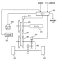
図1を参照して、本実施の形態に係る潤滑油制御装置の制御ブロック図について説明する。図1に示すように、この潤滑油制御装置は、ECU(Electronic Control Unit)100と、エンジン200の回転軸に接続されたベルト式無段変速機のプライマリプーリ300の回転数N(1)を検知する入力軸回転数センサ310と、ベルト式無段変速機のセカンダリプーリ400の回転数N(2)を検知する出力軸回転数センサ410と、オイルポンプ600と、油圧回路700とを含む。
【0044】
ECU100には、他のECUなどから車速信号やアクセル開度信号などが入力されるとともに、要求変速比γ(0)が出力される。
【0045】
エンジン200からの出力によりベルト式無段変速機のプライマリプーリ300が回転する。無端金属ベルト350によりエンジンの回転トルクがセカンダリプーリ400に伝達される。セカンダリプーリ400の回転トルクは伝達機構450を介して駆動輪500に伝達される。
【0046】
ECU100には、オイルポンプ600と油圧回路700とが接続されている。ECU100は、変速比の指令値と実測値とに基づいて、ベルト滑りが生じる可能性があるかベルト滑りが生じていると判断すると、油圧回路700を制御して、無端金属ベルト350とプライマリプーリ300およびセカンダリプーリ400との間に供給される潤滑油の流量を増加させる。
【0047】
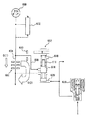
図2を参照して、油圧回路700について説明する。この油圧回路700は、無端金属ベルト350とプライマリプーリ300およびセカンダリプーリ400とに供給する潤滑油量をベルト滑り状態に応じて変更するように構成される。図2に示すように、この潤滑回路700は、潤滑油の元圧を発生させる潤滑調圧バルブ602と、無端金属ベルト350とプライマリプーリ300およびセカンダリプーリ400とを含む潤滑部位とが、流路断面積の小さい第1の油路604、すなわち開口径の小さい小オリフィス606を介装した第1の油路604によって連通されている。その小オリフィス606をバイパスする、流路断面積の大きい第2の油路608、すなわち小オリフィス606より開口径の大きい大オリフィス610を介装した第2の油路608が設けられている。
【0048】
この第2の油路608を開閉する切換バルブ612がこの第2の油路608に介装されている。この切換バルブ612は、一例としてスプールバルブであって、スプール614を一方向に押圧するスプリング616が設けられるとともに、そのスプリング616と同方向に油圧を作用させる第1の制御ポート618と、スプール614を挟んで第1の制御ポート618とは反対側に設けられた第2の制御ポート620とを備えている。そして、第1の制御ポート618および第2の制御ポート620に油圧が印加される。電磁弁630がオフの状態では、第2の制御ポート620に油圧が印加され、スプール614がスプリング616に抗して移動し、第2の油路608を開くようになっている。このとき、第1の油路604における潤滑油の流量Q(1)よりも、第2の油路608における潤滑油の流量Q(2)の方が大きい。
【0049】
また、図2に示す油圧回路に代えて、図3に示す油圧回路であってもよい。図3に示すように、電磁弁660がオンの状態では、ベルト潤滑流量切換バルブ650は開かないで、潤滑油の流量はQ(1)である。電磁弁660がオフの状態では、ベルト潤滑流量切換バルブ650が開いて、潤滑油の流量は{Q(1)+Q(2)}になる。
【0050】
図4を参照して、本実施の形態に係る潤滑油制御装置のECU100で実行されるプログラムの制御構造について説明する。
【0051】
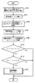
ステップ(以下ステップをSと略す。)100にて、ECU100は、入力された車速信号およびアクセル開度信号に基づいて、運転者から要求された出力を算出する。S102にて、ECU100は、算出された要求出力に基づいて、要求変速比γ(0)を算出する。この算出された要求変速比γ(0)に基づいて、ECU100は、無段変速機のプライマリプーリ300およびセカンダリプーリ400におけるベルト溝幅を制御する。
【0052】
S104にて、ECU100は、プライマリプーリ300の回転数N(1)およびセカンダリプーリ400の回転数N(2)を検知する。この検知は、プライマリプーリ300の近傍に設けられた入力軸回転数センサ310から入力された信号およびセカンダリプーリ400の近傍に設けられた出力軸回転数センサ410から入力された信号に基づいて行なわれる。S106にて、ECU100は実際の変速比γ(1)を算出する。このとき、γ(1)は、N(1)/N(2)で算出される。S108にて、ECU100は、実際の変速比γ(1)の時間変化率dγ(1)/dtを算出する。
【0053】
S110にて、ECU100は、実際の変速比γ(1)が要求変速比γ(0)+αよりも大きいか否かを判断する。ここで、αは予め定められた定数である。実際の変速比γ(1)の方が要求変速比γ(0)よりも予め定められた定数α分を加算したよりも大きい場合とは、要求変速比γ(0)に対して、しきい値であるα分を加算しても実際の変速比γ(1)の方が大きく、無端金属ベルト350と、プライマリプーリ300およびセカンダリプーリ400との間で滑りが生じていること、または滑りが生じる可能性があることを示す。実際の変速比γ(1)が要求変速比γ(0)+αよりも大きい場合には(S110にてYES)、処理はS112へ移される。もしそうでないと(S110にてNO)、この処理は終了する。
【0054】
S112にて、ECU100は、実際の変速比γ(1)の時間変化率dγ(1)/dtがβよりも大きいか否かを判断する。ここで、βは予め定められた定数である。時間変化率dγ(1)/dtが予め定められた定数βよりも大きい場合には(S112にてYES)、処理はS150へ移される。もしそうでないと(S112にてNO)、この処理は終了する。
【0055】
S150にて、ECU100は、潤滑流量増加サブルーチンを実行する。
図5を参照して、潤滑流量増加サブルーチンについて説明する。S160にて、ECU100は断面積の大きな油路を開くための電磁弁に作動を指示する。
【0056】
以上のような構造およびフローチャートに基づく、本実施の形態に係る潤滑流量制御装置の動作について説明する。
【0057】
車速アクセル開度などに基づいて運転者から要求された出力が算出され(S100)、要求変速比γ(0)が算出される(S102)。プライマリプーリ300の回転数N(1)とセカンダリプーリ400の回転数N(2)とが検知され(S104)、実際の変速比γ(1)がN(1)/N(2)で算出される(S106)。また、実際の変速比γ(1)の時間変化率dγ(1)/dtが算出される(S108)。
【0058】
実際の変速比γ(1)が要求変速比γ(0)+αよりも大きく(S110にてYES)、実際の変速比γ(1)の時間変化率dγ(1)/dtがβよりも大きいと(S112にてYES)、無端金属ベルト350とプライマリプーリ300およびセカンダリプーリ400との間で滑りが生じている、または滑りが生じる可能性がある状態と判断される。この場合、潤滑流量増加サブルーチンが実行される(S150)。潤滑流量増加サブルーチンが実行されると、図2に示す流量Q(1)がQ(2)に変更され、無端金属ベルト350とプライマリプーリ300およびセカンダリプーリ400とに供給される潤滑油の流量が増加される。
【0059】
または、図3に示すように、流量Q(1)が流量{Q(1)+Q(2)}になり、無端金属ベルト350とプライマリプーリ300およびセカンダリプーリ400とに供給される潤滑油の流量が増加される。
【0060】
以上のようにして、本実施の形態に係る潤滑油制御装置によると、無段変速機のプライマリプーリの回転数に基づいて算出された実際の変速比と要求変速比とを比較および実際の変速比の時間変化率を算出して、ベルトとプーリとの間の滑りが生じている状態、またはベルトとプーリとの間で滑りが生じる可能性がある状態を検知する。このような状態を検知すると、潤滑油の油路を断面積の大きい油路に変更して、ベルトおよびプーリに供給される潤滑油の流量を増大させる。これにより、ベルトとプーリとの間で滑りが生じている状態または滑りが生じる可能性がある状態になると、潤滑油の流量が増大されて、ベルトとプーリとの間の滑りが生じても、十分に潤滑されるのでベルトおよびプーリが摩耗することなく、無段変速機の寿命が短くなることはない。さらに、ベルト挟圧力を著しく高くする必要がないため、車両の燃費も向上する。
【0061】
<第1の実施の形態 第1の変形例>
以下、本実施の形態の第1の変形例について説明する。第1の実施の形態において、無端金属ベルト350とプライマリプーリ300およびセカンダリプーリ400とを含む潤滑部位に対する潤滑油の流量を増加させる場合、流路断面積を拡大したが、本変形例は、供給圧を高くするものである。その他の制御ブロックおよびフローチャートは、前述の第1の実施の形態と同じであるため、ここでの詳細な説明は繰返さない。
【0062】
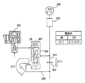
図6に本変形例に係る油圧回路を示す。潤滑用調圧バルブ670はライン圧を元圧として潤滑油圧を調圧する調圧バルブであって、スプール672がその軸線方向に移動することにより、入力ポート674とドレーンポート676とを連通/遮断するように構成されている。そのスプール672の一方の端部には、調圧レベルを決めているスプリング678が配置され、これとは反対側の端部にフィードバックポート680が形成され、このフィードバックポート680がオリフィス682を介して入力ポート674に連通されている。そしてその入力ポート674が潤滑油路684に連通されている。したがって潤滑油路684の油圧すなわち潤滑油圧が、スプール672をスプリング678に抗して移動させる程度の圧力に高くなるまでは、スプール672が図示の位置にとどまって入力ポート674を遮断し、その圧力に達するとスプール672がスプリング678の弾性力に抗して移動し、その結果、入力ポート674がドレーンポート676に連通するので、それ以上の圧力に高くなることがない。すなわち、スプリング678の弾性力によって定まる油圧が潤滑油路684に生じるようになっている。
【0063】
このような構成に加えて、スプリング678を配置してある端部に、制御ポート686が形成され、ここにオンオフ制御される電磁弁690が連通されている。この電磁弁690は、例えばオフ状態で信号圧を出力するノーマルオープンタイプのバルブであって、その信号圧を調圧バルブ670におけるスプリング678側に印加するように構成されている。すなわち調圧バルブ670の調圧レベルは、スプール672をフィードバックポート680側に押圧する荷重によって決まるので、上記の電磁弁690は潤滑油圧の調圧レベルを高くする手段として構成されている。すなわち、電磁弁690をオフ状態にして信号圧を印加して、調圧レベルを上昇させる。なお、この電磁弁690は、ECU100により制御される。
【0064】
図7を参照して、本変形例に係る流量増加サブルーチンについて説明する。S170にて、ECU100は、調圧バルブで油圧を上昇させるための電磁弁に作動を指示する。
【0065】
以上のような構造およびフローチャートに基づく本変形例に係る潤滑油制御装置の動作について説明する。なお、潤滑流量増加処理以外の処理については、前述の第1の実施の形態に係る潤滑油制御装置の動作と同じであるため、ここでの詳細な説明は繰返さない。
【0066】
実際の変速比γ(1)が要求変速比γ(0)+αよりも大きく(S110にてYES)、実際の変速比γ(1)の時間変化率dγ(1)/dtがβよりも大きいと(S112にてYES)、調圧バルブ670で油圧を上昇させるための電磁弁690に作動を指示する。このとき、図6に示す電磁弁690がオフ状態とされ、調圧バルブ670の制御ポート686に信号圧を印加する。これにより、調圧バルブ670は調圧レベルを上昇させる。
【0067】
以上のようにして、本変形例に係る潤滑油制御装置によると、無段変速機のベルトとプーリとの間に滑りが生じている状態、または滑りが生じる可能性がある状態を検知すると、オイルポンプからベルトおよびプーリに供給される油圧を上昇させて、潤滑油の油量を上昇させることができる。
【0068】
<第1の実施の形態 第2の変形例>
以下、本実施の形態の第2の変形例について説明する。第1の実施の形態において、無端金属ベルト350およびプライマリプーリ300およびセカンダリプーリ400とを含む潤滑部位に対する潤滑油の流量を増加させる場合、流路断面積を拡大したが、本変形例は、電動のオイルポンプ600を制御することにより、潤滑油の流量を増加させるものである。その他の制御ブロックおよびフローチャートは、前述の第1の実施の形態と同じであるため、ここでの詳細な説明は繰返さない。
【0069】
図8を参照して、本変形例に係る潤滑油制御装置のECU100で実行される潤滑油流量増加サブルーチンについて説明する。S180にて、ECU100は、オイルポンプ600の回転数を上昇させるように、オイルポンプ制御回路に指示する。
【0070】
以上のような構造およびフローチャートに基づく、本変形例に係る潤滑油制御装置の動作について説明する。
【0071】
実際の変速比γ(1)が要求変速比γ(0)+αよりも大きく(S110にてYES)、実際の変速比γ(1)の時間変化率dγ(1)/dtがβよりも大きいと(S112にてYES)、オイルポンプ600の回転数が上昇される。オイルポンプ600の回転数が上昇すると、オイルポンプ600から油路を介して無端金属ベルト350とプライマリプーリ300およびセカンダリプーリ400とに供給される潤滑油の流量が増加する。
【0072】
以上のようにして、本変形例に係る潤滑油制御装置によっても、ベルトとプーリとの間に滑りが生じているまたは滑りが生じる可能性があると、電動オイルポンプの回転数を上昇させて、潤滑油の流量を増加させることができる。
【0073】
<第2の実施の形態>
以下、本発明の第2の実施の形態に係る潤滑油制御装置について説明する。なお、本実施の形態に係る潤滑油制御装置は、ベルトとプーリとの間の滑りが生じている状態、またはベルトとプーリとの間に滑りが生じる可能性がある状態を、前述の第1の実施の形態に係る潤滑油制御装置とは別の方法で検知するものである。それ以外の処理は、前述の第1の実施の形態と同じである。したがって、前述の第1の実施の形態の潤滑油制御装置と同じ制御ブロック図およびフローチャートについてのここでの詳細な説明は繰返さない。
【0074】
図9を参照して、本実施の形態に係る潤滑油制御装置のECU100で実行されるプログラムの制御構造について説明する。
【0075】
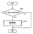
S200にて、ECU100は、ベルト挟圧力上昇指令を検知したか否かを判断する。ベルト挟圧力上昇指令とは、ベルトがプーリとの間で滑りを生じている状態や滑りを生じる可能性がある状態を、運転者の操作や車両の運転状態などから判断して、ECU100が、無段変速機に対して送信する制御信号である。ベルト挟圧力上昇指令を検知すると(S200にてYES)、処理はS150の潤滑流量増加サブルーチンに移される。もしそうでないと(S200にてNO)、この処理は終了する。
【0076】
以上のような構造フローチャートに基づく、本実施の形態に係る潤滑油制御装置の動作について説明する。
【0077】
運転者の操作(ブレーキ操作、アクセル操作など)と車両の運転状態とに基づいて、ECU100がベルト挟圧力上昇指令を無段変速機100へ出力すると(S200にてYES)、潤滑流量増加サブルーチン(S150)が実行される。すなわち、ECU100が、ベルトとプーリとの間に滑りが生じている状態またはベルトとプーリとの間に滑りが生じる可能性がある状態を検知すると、ベルト挟圧力上昇指令を無段変速機に送信する。ECU100は、このベルト挟圧力上昇指令に基づいて、潤滑流量増加サブルーチンを実行する。
【0078】
この潤滑流量増加サブルーチンについては、前述の第1の実施の形態に記載したように、油路の流路断面積を増加させる方法、潤滑油の油圧を上昇させる方法および潤滑油を供給する電動オイルポンプの回転数を増加させる方法のいずれであってもよい。
【0079】
以上のようにして、本実施の形態に係る潤滑油制御装置によると、ベルト挟圧力上昇指令が出力されると、潤滑油の流量を増加させることができる。これにより、無段変速機におけるベルトとプーリとの間で滑りが生じている状態や滑りが生じる可能性がある状態になると、ベルト挟圧力上昇指令を検知して、潤滑油の流量を増加させることができる。
【0080】
<第3の実施の形態>
以下、本発明の第2の実施の形態に係る潤滑油制御装置について説明する。なお、本実施の形態に係る潤滑油制御装置は、ベルトとプーリとの間の滑りが生じている状態、またはベルトとプーリとの間に滑りが生じる可能性がある状態を、前述の第1の実施の形態に係る潤滑油制御装置とは別の方法で検知するものである。それ以外の処理は、前述の第1の実施の形態と同じである。したがって、前述の第1の実施の形態の潤滑油制御装置と同じ制御ブロック図およびフローチャートについてのここでの詳細な説明は繰返さない。
【0081】
本実施の形態に係る潤滑油制御装置は、車速、アクセル開度、レンジ信号、油温、変速比などの情報に基づいて、ベルト滑りの検出またはベルト滑りを推定すると潤滑油量を増加させる制御構造を有する。図10を参照して、本実施の形態に係る潤滑油制御装置のECU100で実行されるプログラムの制御構造について説明する。
【0082】
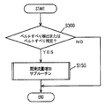
S300にて、ECU100はベルト滑り検出またはベルト滑り推定をしたか否かを判断する。このベルト滑り検出またはベルト滑り推定は、ECU100に入力される各種のセンシング量に基づいて判断される。たとえば、ECU100は、登坂路で停車中の車両が発進することを検知したり、低μ路で急ブレーキがかけられたことを検知したり、後退中の車両において、変速レンジが「R」レンジから「D」レンジに切換えられたことを検知したり、エンジン始動直後の車両において、変速レンジが「N」レンジから「D」レンジに急に切換えられたことを検知したりすると、ベルト滑り検出またはベルト滑り推定と判断する。このような車両の運転状態において、運転者によるこのような操作が実行された場合には、ベルトが滑ると検出したりベルトが滑ると推定したりする。ベルト滑り検出またはベルト滑り推定と判断されると(S300にてYES)、処理はS150の潤滑流量増加サブルーチンに移される。もしそうでないと(S300にてNO)、この処理は終了する。
【0083】
以上のような構造およびフローチャートに基づく、本実施の形態に係る潤滑油制御装置の動作について説明する。
【0084】
登坂路において停車中の車両が再発進する場合などにおいて、運転者がアクセルを開くと、ベルト滑り検出またはベルト滑り推定と判断される(S300にてYES)。ECU100は、この判断に基づいて、潤滑流量増加サブルーチンを実行する。
【0085】
この潤滑流量増加サブルーチンについては、前述の第1の実施の形態に記載したように、油路の流路断面積を増加させる方法、潤滑油の油圧を上昇させる方法および潤滑油を供給する電動オイルポンプの回転数を増加させる方法のいずれであってもよい。
【0086】
以上のようにして、本実施の形態に係る潤滑油制御装置によると、運転者の操作や車両の運転状態に基づいて、ベルト滑り検出またはベルト滑り推定を行ない、ベルト滑り検出またはベルト滑り推定と判断されると、ベルトおよびプーリに供給される潤滑油の流量を増加させることができる。
【0087】
今回開示された実施の形態はすべての点で例示であって制限的なものではないと考えられるべきである。本発明の範囲は上記した説明ではなくて特許請求の範囲によって示され、特許請求の範囲と均等の意味および範囲内でのすべての変更が含まれることが意図される。
【図面の簡単な説明】
【図1】本発明の第1の実施の形態に係る潤滑油制御装置のブロック図である。
【図2】本発明の第1の実施の形態に係る潤滑油制御装置における油圧回路を示す図(その1)である。
【図3】本発明の第1の実施の形態に係る潤滑油制御装置における油圧回路を示す図(その2)である。
【図4】本発明の第1の実施の形態に係る潤滑油制御装置のECUで実行されるプログラムの制御構造を表わすフローチャートである。
【図5】本発明の第1の実施の形態に係る潤滑油制御装置のECUで実行される潤滑流量増加サブルーチンの制御構造を表わすフローチャートである。
【図6】本発明の第1の実施の形態の第1の変形例に係る潤滑油制御装置における油圧回路を示す図である。
【図7】本発明の第1の実施の形態の第1の変形例に係る潤滑油制御装置のECUで実行される潤滑流量増加サブルーチンの制御構造を表わすフローチャートである。
【図8】本発明の第1の実施の形態の第2の変形例に係る潤滑油制御装置のECUで実行される潤滑流量増加サブルーチンの制御構造を表わすフローチャートである。
【図9】本発明の第2の実施の形態に係る潤滑油制御装置のECUで実行されるプログラムの制御構造を表わすフローチャートである。
【図10】本発明の第3の実施の形態に係る潤滑油制御装置のECUで実行されるプログラムの制御構造を表わすフローチャートである。
【符号の説明】
100 ECU、200 エンジン、300 プライマリプーリ、310 入力軸回転数センサ、350 無端金属ベルト、400 セカンダリプーリ、410 出力軸回転数センサ、500 駆動輪、600 オイルポンプ、700 油圧回路。[0001]
TECHNICAL FIELD OF THE INVENTION
The present invention relates to an endless metal belt using an endless metal belt formed by, for example, arranging a large number of plate-like elements facing each other in an annular shape, and binding these elements in an annular shape through a hoop as a metal band to the elements. More particularly, the present invention relates to a control device for controlling the amount of lubricating oil for preventing breakage of an endless metal belt.
[0002]
[Prior art]
In some vehicles, a belt-type continuously variable transmission (CVT: Continuously Variable Transmission) that adjusts the transmission gear ratio steplessly according to the traveling state of the vehicle is mounted. This CVT can efficiently extract the engine output, and is excellent in improving fuel efficiency and running performance. As one of the CVTs put into practical use, there is a CVT that uses a metal belt and a pair of pulleys to continuously change the speed continuously by changing the effective diameter of the pulley by hydraulic pressure. An endless metal belt is used by being wound around an input pulley attached to an input shaft and an output pulley attached to an output shaft. The input pulley and the output pulley each include a pair of sheaves whose groove width can be changed steplessly. By changing the groove width, the winding radius of the endless metal belt around the input pulley and the output pulley changes, As a result, the rotational speed ratio between the input shaft and the output shaft, that is, the gear ratio can be continuously and continuously changed.
[0003]
In such a CVT, lubricating oil is supplied between the belt and the pulley in order to prevent wear of the belt and the pulley. Such a CVT lubrication device is described in JP-A-8-254260 (Patent Document 1), JP-A-9-53711 (Patent Document 2), and JP-A-2000-74913 (Patent Document 3). .
[0004]
The lubricating device for a belt-type continuously variable transmission described in
[0005]
According to the lubricating device described in
[0006]
The cooling device for a belt-type continuously variable transmission described in
[0007]
According to the cooling device described in
[0008]
The lubricating device described in Patent Literature 3 has an input pulley and an output pulley capable of continuously changing a contact width with a belt, and a lubricating oil supply that supplies lubricating oil between the input pulley and the output pulley and the belt. Temperature sensor that detects the temperature of lubricating oil scattered from the belt provided on the outer peripheral portion of the belt, and the amount of lubricating oil supplied by the lubricating oil supply unit is detected by the oil temperature sensor. And a lubricating oil amount determining circuit for determining the amount of lubricating oil.
[0009]
According to the lubricating device described in Patent Literature 3, an oil temperature sensor that detects the temperature of lubricating oil scattered from the belt is installed at the outer peripheral portion of the belt, and the amount of lubricating oil supplied by the lubricating oil supply circuit is measured by the oil temperature sensor. A circuit for determining the amount of lubricating oil which is determined in accordance with the temperature of the scattered lubricating oil detected in the above was installed. This makes it possible to reliably supply a necessary amount of lubricating oil in accordance with the heat generation state of the belt and the pulley, thereby improving the durability reliability of the belt and the pulley. Furthermore, the amount of lubricating oil supplied to the belt can always be suppressed to a necessary minimum, the drive loss of the hydraulic pump can be reduced, and the fuel efficiency of the continuously variable transmission can be improved.
[0010]
[Patent Document 1]
JP-A-8-254260
[0011]
[Patent Document 2]
JP-A-9-53711
[0012]
[Patent Document 3]
JP 2000-74913 A
[0013]
[Problems to be solved by the invention]
In the continuously variable transmission to which the lubrication device and the cooling device described in the above-mentioned publications are applied, the belt is sandwiched between the pulleys so that the belt does not slip between the belt and the pulley, and the belt is connected to the pulley. I'm pushing. For this reason, in the lubricating device and the cooling device described in the above-mentioned publications, the amount of the lubricating oil is controlled based on the speed ratio and the oil temperature on the assumption that no slippage occurs between the belt and the pulley. I do. However, if the pressing force for pressing the belt against the pulley is increased so that the belt slip does not occur reliably, the fuel efficiency of the vehicle decreases. If the pressing force is not increased to avoid this, the belt slips when the load on the belt is increased depending on the driving condition. At this time, in the lubricating device and the cooling device described in the above-mentioned publications, the oil amount is controlled irrespective of the belt slip occurring. Therefore, the belt and the pulley are worn by the generated belt slip, and the life of the continuously variable transmission is shortened.
[0014]
The present invention has been made in order to solve the above-mentioned problems, and a control device for a belt-type continuously variable transmission that does not shorten the life of the continuously variable transmission without deteriorating the fuel efficiency of the vehicle and a control thereof. An object of the present invention is to provide a belt-type continuously variable transmission provided with a device.
[0015]
[Means for Solving the Problems]
A control device according to a first aspect of the present invention controls the amount of lubricating oil in a belt-type continuously variable transmission including a pair of pulleys having variable groove widths and a belt wound around these pulleys. The control device includes: an acquiring unit configured to acquire information on a slip generated between the belt and the pulley; and an amount of lubricating oil supplied between the belt and the pulley based on the information acquired by the acquiring unit. And lubricating oil amount control means for controlling the amount of lubricating oil.
[0016]
According to the first aspect, when the information that the slip is likely to occur between the belt and the pulley or the information that the slip is generated is obtained by the obtaining unit, the belt and the pulley are determined based on such information. To increase the amount of lubricating oil to be supplied. The amount of lubricating oil can be increased when belt slippage occurs, and deterioration of the durability of the belt and pulley due to belt slippage can be avoided. There is no need to increase the pressing force for pressing the belt against the pulley in order to completely eliminate the belt slippage, and the fuel efficiency of the vehicle does not decrease. As a result, it is possible to provide a control device for a belt-type continuously variable transmission that does not deteriorate the fuel efficiency of the vehicle and does not shorten the life of the continuously variable transmission.
[0017]
In the control device according to a second aspect of the present invention, in addition to the configuration of the first aspect, the acquisition means acquires information indicating that the vehicle is in a vehicle operating state in which slippage may occur. The lubricating oil amount control means controls to increase the lubricating oil amount in response to the information indicating that the vehicle is in a vehicle operating state in which slippage may occur.
[0018]
According to the second aspect, the amount of lubricating oil is increased in response to the information indicating that the vehicle is in a vehicle operating state in which slippage may occur, and the amount of the belt and the pulley is reduced due to the belt slippage. Deterioration of durability can be avoided.
[0019]
In a control device according to a third aspect of the present invention, in addition to the configuration of the first aspect, the acquisition means acquires information indicating that the vehicle is in a vehicle driving state in which slippage has occurred. The lubricating oil amount control means controls to increase the lubricating oil amount in response to the acquisition of information indicating that the vehicle is in a slipping vehicle operating state.
[0020]
According to the third invention, the amount of lubricating oil is increased in response to the information indicating that the vehicle is in a slipping vehicle driving state, and the durability of the belt and the pulley is increased due to the belt slip. Can be prevented from becoming worse.
[0021]
The control device according to a fourth aspect of the present invention is the control device according to any one of the first to third aspects, wherein the acquisition unit compares the command value of the speed ratio in the continuously variable transmission with an actually measured value to thereby control the belt speed. Means for obtaining information about slippage between the pulley and the pulley.
[0022]
According to the fourth aspect, the command value of the speed ratio in the continuously variable transmission is compared with the actually measured value, and the actually measured value of the speed ratio represented by the input shaft speed / the output shaft speed matches the command value. Otherwise, it can be determined that slippage has occurred.
[0023]
The control device according to a fifth aspect of the present invention is the control device according to the fourth aspect, wherein the acquisition unit determines that the measured value is out of a predetermined range with respect to the command value, the distance between the belt and the pulley. The vehicle includes a means for acquiring information indicating that the vehicle is in a vehicle driving state in which a slip is likely to occur or a vehicle driving state in which a slip is occurring.
[0024]
According to the fifth aspect, the command value of the speed ratio in the continuously variable transmission is compared with the actually measured value, and if the actually measured value of the speed ratio represented by the input shaft rotation speed / the output shaft rotation speed is larger than the command value. It can be determined that slippage has occurred based on the fact that the output shaft speed has not increased.
[0025]
The control device according to a sixth aspect of the present invention is the control device according to the fourth aspect, wherein the acquisition means is configured such that the measured value is out of a predetermined range with respect to the command value, and the time change rate of the measured value is Means for acquiring information indicating that the vehicle is in a vehicle operating state in which a slip may occur between the belt and the pulley when the rate of change is equal to or greater than a predetermined change rate, or a vehicle operating state in which a slip occurs. including.
[0026]
According to the sixth aspect, the command value of the speed ratio in the continuously variable transmission is compared with the actually measured value, and the measured value of the speed ratio represented by the input shaft speed / output shaft speed matches the command value. If there is no change and the time change rate of the actually measured value of the gear ratio is large, it can be determined that slippage has occurred.
[0027]
The control device according to a seventh aspect of the present invention is the control device according to any one of the fourth to sixth aspects, wherein the actually measured value is calculated based on the input shaft speed and the output shaft speed in the continuously variable transmission. Things.
[0028]
According to the seventh aspect, the actually measured value of the speed ratio can be easily calculated based on the input shaft speed and the output shaft speed in the continuously variable transmission.
[0029]
The control device according to an eighth aspect of the present invention is the control device according to any one of the first to third aspects, wherein the acquiring means determines whether the belt and the pulley have a distance between the belt and the pulley based on a command value of a belt clamping pressure in the continuously variable transmission. Means for obtaining information about slippage occurring in the vehicle.
[0030]
According to the eighth aspect, in the continuously variable transmission, when the driving state of the vehicle in which the belt slips is detected, a command value for increasing, for example, the belt clamping pressure is output. When a command value that increases the belt clamping pressure is detected, it can be determined that slippage has occurred or slippage has occurred.
[0031]
In the control device according to a ninth aspect, in addition to the configuration according to the eighth aspect, when the command value is a value that increases the belt clamping pressure, there is a possibility that slippage may occur between the belt and the pulley. Means for acquiring information indicating that there is a certain vehicle driving state or a vehicle driving state in which slippage occurs.
[0032]
According to the ninth aspect, in the continuously variable transmission, when the driving state of the vehicle in which the belt slips is detected, a command value for increasing the belt clamping pressure is output. When a command value that increases the belt clamping pressure is detected, it can be determined that slippage has occurred or slippage has occurred.
[0033]
The control device according to a tenth aspect of the present invention is the control device according to any one of the first to third aspects, wherein the acquisition unit is configured to perform the operation between the belt and the pulley based on an operation by a driver of the vehicle and a state of the vehicle. Includes means for obtaining information about the resulting slip.
[0034]
According to the tenth aspect, for example, when a vehicle stopped on an uphill road is started, the driver steps on the accelerator to start the vehicle so that the vehicle does not move backward. At this time, if the vehicle speed is low, the accelerator opening is large, the range signal is in the D range, and the gear ratio is large, the vehicle on the uphill road may stop and the belt may slip. In this way, based on the operation of the vehicle driver and the state of the vehicle, it can be determined that slippage or slippage occurs between the belt and the pulley.
The control device according to an eleventh aspect of the present invention is the control device according to any one of the first to tenth aspects, wherein the lubricating oil amount control means includes a first lubricating oil passage and a first lubricating oil passage. Means for controlling the amount of lubricating oil by switching to a second lubricating oil passage having a flow path cross-sectional area larger than the area.
[0035]
According to the eleventh aspect, when slippage occurs or slippage may occur, the first lubricating oil path has a flow path cross-sectional area larger than the flow path cross-sectional area of the first lubricating oil path. By switching to the second lubricating oil passage, the amount of lubricating oil can be increased.
[0036]
The control device according to a twelfth aspect is the control device according to any of the first to tenth aspects, wherein the lubricating oil amount control unit controls the oil amount of the lubricating oil by adjusting the oil pressure of the lubricating oil. Means.
[0037]
According to the twelfth aspect, when slippage or slippage is likely to occur, the oil pressure of the lubricating oil can be increased to increase the amount of lubricating oil.
[0038]
A control device according to a thirteenth aspect of the present invention is the control device according to any one of the first to tenth aspects, wherein the lubricating oil amount control means controls the electric oil pump for supplying the lubricating oil, thereby reducing the lubricating oil. Includes means for controlling the amount.
[0039]
According to the thirteenth aspect, when slippage occurs or slippage may occur, the number of rotations of the electric oil pump that supplies the lubricating oil can be increased to increase the amount of lubricating oil.
[0040]
A belt-type continuously variable transmission according to a fourteenth invention includes a control device limited by the configuration of any one of the first to thirteenth inventions.
[0041]
According to the fourteenth aspect, when the information that the slip is likely to occur between the belt and the pulley or the information that the slip is occurring is obtained by the obtaining unit, the information of the belt and the pulley is determined based on such information. Increase the amount of lubricating oil supplied in between. The amount of lubricating oil can be increased when belt slippage occurs, and deterioration of the durability of the belt and pulley due to belt slippage can be avoided. There is no need to increase the pressing force for pressing the belt against the pulley in order to completely eliminate the belt slippage, and the fuel efficiency of the vehicle does not decrease. As a result, it is possible to provide a belt-type continuously variable transmission that does not shorten the service life without deteriorating the fuel efficiency of the vehicle.
[0042]
BEST MODE FOR CARRYING OUT THE INVENTION
Hereinafter, embodiments of the present invention will be described with reference to the drawings. In the following description, the same components are denoted by the same reference numerals. Their names and functions are the same. Therefore, detailed description thereof will not be repeated.
[0043]
<First embodiment>
A control block diagram of the lubricating oil control device according to the present embodiment will be described with reference to FIG. As shown in FIG. 1, this lubricating oil control device controls an electronic control unit (ECU) 100 and a rotation speed N (1) of a
[0044]
The
[0045]
The output from
[0046]
The
[0047]
The
[0048]
A switching
[0049]
Further, instead of the hydraulic circuit shown in FIG. 2, a hydraulic circuit shown in FIG. 3 may be used. As shown in FIG. 3, when the
[0050]
Referring to FIG. 4, a control structure of a program executed by
[0051]
In step (hereinafter, step is abbreviated as S) 100,
[0052]
In S104,
[0053]
In S110,
[0054]
In S112,
[0055]
At S150,
The lubricating flow rate increasing subroutine will be described with reference to FIG. In S160,
[0056]
The operation of the lubrication flow control device according to the present embodiment based on the above structure and flowchart will be described.
[0057]
An output requested by the driver is calculated based on the vehicle speed accelerator opening and the like (S100), and a requested gear ratio γ (0) is calculated (S102). The rotation speed N (1) of the
[0058]
Actual speed ratio γ (1) is larger than required speed ratio γ (0) + α (YES in S110), and time change rate dγ (1) / dt of actual speed ratio γ (1) is larger than β. (YES in S112), it is determined that slippage has occurred between
[0059]
Alternatively, as shown in FIG. 3, the flow rate Q (1) becomes the flow rate {Q (1) + Q (2)}, and the flow rate of the lubricating oil supplied to the
[0060]
As described above, according to the lubricating oil control device according to the present embodiment, the actual gear ratio calculated based on the rotation speed of the primary pulley of the continuously variable transmission is compared with the required gear ratio, and the actual gear ratio is calculated. The time change ratio of the ratio is calculated to detect a state in which slippage occurs between the belt and the pulley, or a state in which slippage may occur between the belt and the pulley. When such a state is detected, the oil passage of the lubricating oil is changed to an oil passage having a large sectional area, and the flow rate of the lubricating oil supplied to the belt and the pulley is increased. Thereby, when a state in which a slip occurs between the belt and the pulley or a state in which a slip is likely to occur, the flow rate of the lubricating oil is increased, and even if the slip between the belt and the pulley occurs, The lubrication is sufficient so that the belts and pulleys do not wear and the life of the continuously variable transmission is not shortened. Further, since it is not necessary to significantly increase the belt clamping pressure, the fuel efficiency of the vehicle is improved.
[0061]
<First Embodiment First Modification>
Hereinafter, a first modified example of the present embodiment will be described. In the first embodiment, when the flow rate of the lubricating oil to the lubricating portion including the
[0062]
FIG. 6 shows a hydraulic circuit according to this modification. The lubricating
[0063]
In addition to such a configuration, a
[0064]
With reference to FIG. 7, the flow rate increase subroutine according to the present modification will be described. In S170,
[0065]
The operation of the lubricating oil control device according to the present modification based on the above structure and flowchart will be described. The processes other than the lubricating flow rate increasing process are the same as the operations of the lubricating oil control device according to the above-described first embodiment, and therefore, detailed description thereof will not be repeated.
[0066]
Actual speed ratio γ (1) is larger than required speed ratio γ (0) + α (YES in S110), and time change rate dγ (1) / dt of actual speed ratio γ (1) is larger than β. (YES in S112), an operation is instructed to
[0067]
As described above, according to the lubricating oil control device according to the present modification, when a state in which slippage occurs between the belt and the pulley of the continuously variable transmission, or a state in which slippage is likely to occur, is detected. By increasing the oil pressure supplied to the belt and the pulley from the oil pump, the amount of lubricating oil can be increased.
[0068]
<First Embodiment Second Modification>
Hereinafter, a second modified example of the present embodiment will be described. In the first embodiment, when increasing the flow rate of the lubricating oil to the lubricating portion including the
[0069]
Referring to FIG. 8, a description will be given of a lubricating oil flow rate increasing subroutine executed by
[0070]
The operation of the lubricating oil control device according to the present modification based on the above structure and flowchart will be described.
[0071]
Actual speed ratio γ (1) is larger than required speed ratio γ (0) + α (YES in S110), and time change rate dγ (1) / dt of actual speed ratio γ (1) is larger than β. (YES in S112), the rotation speed of
[0072]
As described above, even with the lubricating oil control device according to the present modification, when slippage occurs between the belt and the pulley or when slippage may occur, the rotation speed of the electric oil pump is increased. As a result, the flow rate of the lubricating oil can be increased.
[0073]
<Second embodiment>
Hereinafter, a lubricating oil control device according to a second embodiment of the present invention will be described. Note that the lubricating oil control device according to the present embodiment sets the state in which slippage occurs between the belt and the pulley, or the state in which slippage may occur between the belt and the pulley, in the first state described above. The detection is performed by a method different from the lubricating oil control device according to the embodiment. Other processes are the same as those in the first embodiment. Therefore, detailed description of the same control block diagrams and flowcharts as those of the above-described lubricating oil control device of the first embodiment will not be repeated.
[0074]
Referring to FIG. 9, a control structure of a program executed by
[0075]
In S200,
[0076]
The operation of the lubricating oil control device according to the present embodiment based on the above-described structural flowchart will be described.
[0077]
When
[0078]
As described in the first embodiment, the lubricating flow rate increasing subroutine includes a method of increasing the cross-sectional area of the oil passage, a method of increasing the oil pressure of the lubricating oil, and an electric oil for supplying the lubricating oil. Any of the methods for increasing the rotation speed of the pump may be used.
[0079]
As described above, according to the lubricating oil control device according to the present embodiment, when the belt squeezing pressure increase command is output, the flow rate of the lubricating oil can be increased. Accordingly, when a state in which slippage occurs between the belt and the pulley in the continuously variable transmission or a state in which slippage is likely to occur, a belt squeezing pressure increase command is detected and the flow rate of lubricating oil is increased. be able to.
[0080]
<Third embodiment>
Hereinafter, a lubricating oil control device according to a second embodiment of the present invention will be described. Note that the lubricating oil control device according to the present embodiment sets the state in which slippage occurs between the belt and the pulley, or the state in which slippage may occur between the belt and the pulley, in the first state described above. The detection is performed by a method different from the lubricating oil control device according to the embodiment. Other processes are the same as those in the first embodiment. Therefore, detailed description of the same control block diagrams and flowcharts as those of the above-described lubricating oil control device of the first embodiment will not be repeated.
[0081]
The lubricating oil control device according to the present embodiment performs control to increase the amount of lubricating oil when belt slip is detected or belt slip is estimated based on information such as vehicle speed, accelerator opening, range signal, oil temperature, and gear ratio. Having a structure. Referring to FIG. 10, a control structure of a program executed by
[0082]
In S300,
[0083]
The operation of the lubricating oil control device according to the present embodiment based on the above structure and flowchart will be described.
[0084]
When the driver opens the accelerator, for example, when a stopped vehicle restarts on an uphill road, it is determined that belt slippage has been detected or belt slippage has been estimated (YES in S300). The
[0085]
As described in the first embodiment, the lubricating flow rate increasing subroutine includes a method of increasing the cross-sectional area of the oil passage, a method of increasing the oil pressure of the lubricating oil, and an electric oil for supplying the lubricating oil. Any of the methods for increasing the rotation speed of the pump may be used.
[0086]
As described above, according to the lubricating oil control device according to the present embodiment, based on the operation of the driver or the driving state of the vehicle, belt slip detection or belt slip estimation is performed, and belt slip detection or belt slip estimation is performed. When determined, the flow rate of the lubricating oil supplied to the belt and the pulley can be increased.
[0087]
The embodiments disclosed this time are to be considered in all respects as illustrative and not restrictive. The scope of the present invention is defined by the terms of the claims, rather than the description above, and is intended to include any modifications within the scope and meaning equivalent to the terms of the claims.
[Brief description of the drawings]
FIG. 1 is a block diagram of a lubricating oil control device according to a first embodiment of the present invention.
FIG. 2 is a diagram (part 1) illustrating a hydraulic circuit in the lubricating oil control device according to the first embodiment of the present invention.
FIG. 3 is a diagram (part 2) illustrating a hydraulic circuit in the lubricating oil control device according to the first embodiment of the present invention.
FIG. 4 is a flowchart illustrating a control structure of a program executed by an ECU of the lubricating oil control device according to the first embodiment of the present invention.
FIG. 5 is a flowchart illustrating a control structure of a lubricating flow rate increasing subroutine executed by an ECU of the lubricating oil control device according to the first embodiment of the present invention.
FIG. 6 is a diagram showing a hydraulic circuit in a lubricating oil control device according to a first modification of the first embodiment of the present invention.
FIG. 7 is a flowchart illustrating a control structure of a lubricating flow rate increasing subroutine executed by an ECU of a lubricating oil control device according to a first modification of the first embodiment of the present invention.
FIG. 8 is a flowchart illustrating a control structure of a lubricating flow rate increasing subroutine executed by an ECU of a lubricating oil control device according to a second modification of the first embodiment of the present invention.
FIG. 9 is a flowchart illustrating a control structure of a program executed by an ECU of a lubricating oil control device according to a second embodiment of the present invention.
FIG. 10 is a flowchart illustrating a control structure of a program executed by an ECU of a lubricating oil control device according to a third embodiment of the present invention.
[Explanation of symbols]
100 ECU, 200 engine, 300 primary pulley, 310 input shaft speed sensor, 350 endless metal belt, 400 secondary pulley, 410 output shaft speed sensor, 500 drive wheels, 600 oil pump, 700 hydraulic circuit.
Claims (14)
前記ベルトと前記プーリとの間に生じる滑りに関する情報を取得するための取得手段と、
前記取得手段により取得された情報に基づいて、前記ベルトと前記プーリとの間に供給する潤滑油の油量を制御するための潤滑油量制御手段とを含む、制御装置。A control device for controlling the amount of lubricating oil in a belt-type continuously variable transmission including a pair of pulleys having variable groove widths and a belt wound around these pulleys,
Acquisition means for acquiring information about slippage occurring between the belt and the pulley,
A control device including: a lubricating oil amount control unit configured to control an amount of lubricating oil supplied between the belt and the pulley based on the information acquired by the acquiring unit.
前記潤滑油量制御手段は、前記滑りが生じる可能性がある車両運転状態であることを示す情報が取得されたことに応答して前記潤滑油量を増大させるように制御する、請求項1に記載の制御装置。The acquisition means is for acquiring information indicating that the vehicle is in a driving state in which the slip may occur,
2. The lubricating oil amount control unit according to claim 1, wherein the lubricating oil amount control unit performs control so as to increase the lubricating oil amount in response to information indicating that the vehicle is in a vehicle operating state in which the slip may occur. The control device as described.
前記潤滑油量制御手段は、前記滑りが生じている車両運転状態であることを示す情報が取得されたことに応答して前記潤滑油量を増大させるように制御する、請求項1に記載の制御装置。The acquisition means is for acquiring information indicating that the vehicle is in a driving state in which the slip has occurred,
2. The lubricating oil amount control unit according to claim 1, wherein the lubricating oil amount control unit performs control to increase the lubricating oil amount in response to information indicating that the vehicle is in the vehicle operating state in which the slippage occurs. 3. Control device.
Priority Applications (1)
| Application Number | Priority Date | Filing Date | Title |
|---|---|---|---|
| JP2002309509A JP2004144192A (en) | 2002-10-24 | 2002-10-24 | Control device for belt-type continuously variable transmission and belt-type continuously variable transmission including the control device |
Applications Claiming Priority (1)
| Application Number | Priority Date | Filing Date | Title |
|---|---|---|---|
| JP2002309509A JP2004144192A (en) | 2002-10-24 | 2002-10-24 | Control device for belt-type continuously variable transmission and belt-type continuously variable transmission including the control device |
Publications (1)
| Publication Number | Publication Date |
|---|---|
| JP2004144192A true JP2004144192A (en) | 2004-05-20 |
Family
ID=32455297
Family Applications (1)
| Application Number | Title | Priority Date | Filing Date |
|---|---|---|---|
| JP2002309509A Pending JP2004144192A (en) | 2002-10-24 | 2002-10-24 | Control device for belt-type continuously variable transmission and belt-type continuously variable transmission including the control device |
Country Status (1)
| Country | Link |
|---|---|
| JP (1) | JP2004144192A (en) |
Cited By (1)
| Publication number | Priority date | Publication date | Assignee | Title |
|---|---|---|---|---|
| JP2009517616A (en) * | 2005-12-01 | 2009-04-30 | ロベルト ボッシュ ゲゼルシャフト ミト ベシュレンクテル ハフツング | Method of operating continuously variable transmission |
-
2002
- 2002-10-24 JP JP2002309509A patent/JP2004144192A/en active Pending
Cited By (1)
| Publication number | Priority date | Publication date | Assignee | Title |
|---|---|---|---|---|
| JP2009517616A (en) * | 2005-12-01 | 2009-04-30 | ロベルト ボッシュ ゲゼルシャフト ミト ベシュレンクテル ハフツング | Method of operating continuously variable transmission |
Similar Documents
| Publication | Publication Date | Title |
|---|---|---|
| JP3981317B2 (en) | Hydraulic pressure drop detecting device for vehicle transmission | |
| JP5435137B2 (en) | Control device for continuously variable transmission for vehicle | |
| EP2074340B1 (en) | Apparatus and method for controlling continuously variable transmission and program for performing the control method | |
| US8175777B2 (en) | Control apparatus, control method, and computer-readable storage medium for continuously variable transmission | |
| US6461261B2 (en) | Control apparatus and method of continuously variable transmission | |
| CN107161136A (en) | The control device of vehicle driving apparatus | |
| KR100510806B1 (en) | Belt slip prevention system for belt type continuously variable transmission | |
| CN101490443B (en) | Control apparatus and control method of continuously variable transmission | |
| US7044873B2 (en) | Belt-type continuously variable transmission | |
| JP2004124966A (en) | Control device for belt-type continuously variable transmission | |
| JP5447274B2 (en) | Control device for continuously variable transmission for vehicle | |
| JP2009101910A (en) | Vehicle control device | |
| JP2004144192A (en) | Control device for belt-type continuously variable transmission and belt-type continuously variable transmission including the control device | |
| JP4093007B2 (en) | Control device for continuously variable transmission | |
| JP5692030B2 (en) | Hydraulic control device for vehicle | |
| JP3821764B2 (en) | Belt slip prevention system for belt type continuously variable transmission | |
| JP4362943B2 (en) | Shift control device for continuously variable transmission | |
| JP2002327835A (en) | Control device for continuously variable transmission | |
| JP5733060B2 (en) | Control device for belt type continuously variable transmission for vehicle | |
| JP2005315291A (en) | Control device for belt type continuously variable transmission | |
| JP2010265918A (en) | Control device and control method for continuously variable transmission | |
| JP3675329B2 (en) | Belt type continuously variable transmission | |
| CN111022638B (en) | Control device for power transmission mechanism | |
| JP2012172761A (en) | Control device of lock-up clutch for vehicle | |
| JP2004263737A (en) | Transmission control device for continuously variable transmission |
Legal Events
| Date | Code | Title | Description |
|---|---|---|---|
| A621 | Written request for application examination |
Free format text: JAPANESE INTERMEDIATE CODE: A621 Effective date: 20050318 |
|
| A977 | Report on retrieval |
Free format text: JAPANESE INTERMEDIATE CODE: A971007 Effective date: 20071126 |
|
| A131 | Notification of reasons for refusal |
Free format text: JAPANESE INTERMEDIATE CODE: A131 Effective date: 20071211 |
|
| A521 | Written amendment |
Free format text: JAPANESE INTERMEDIATE CODE: A523 Effective date: 20080130 |
|
| A02 | Decision of refusal |
Free format text: JAPANESE INTERMEDIATE CODE: A02 Effective date: 20080415 |