【0001】
【発明の属する技術分野】
この出願の発明は、ミラー扉に関するものである。さらに詳しくは、この出願の発明は、玄関収納家具等に有用な新しいミラー扉に関するものである。
【0002】
【従来の技術】
従来より、収納家具の扉部にミラーを配設したミラー扉が知られている。そして、これらのミラー扉は、収納家具の配置位置や用途に応じて、身体の一部あるいはほぼ全身を映す姿見として利用されている。
【0003】
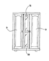
このような従来のミラー扉としては、ミラーを扉本体に埋設したものが代表的なものとして用いられている。たとえば、図10に示したミラー扉(10)は、左右それぞれに配設された2枚の扉(9)の間に配置されており、扉本体にミラー(11)を埋設したものとなっている(特許文献1)。しかしながら、ミラー扉(10)の場合には必然的にミラー(11)の大きさには制限があり、扉本体に埋設可能な平面大きさのものに限られ、どうしても姿見用のミラーとしては幅が狭く、上下の高さも小さいものとなり、不便であった。しかも、ミラー(11)周りの部材については隣接する他の扉との色合いや風合いを整合する必要性があり、使用する部材が多くなるという問題があった。
【0004】
また、このような従来のミラー扉(10)については、i)ミラー(11)に特殊な穴加工を施して把手を取付けるか、あるいはii)扉全体を押すと浮き上がるタッチパネル方式等とすることがしばしばあるが、穴開け加工が面倒であったり、ミラー(11)が汚れやすいという問題があった。
【0005】
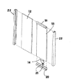
他方、ミラー(11)の扉本体への取付け構造についても、様々なものが既に提案されており、たとえば、ミラーを扉本体に取付けた構造としては、図11に示したように、ミラー板(12)の背面に背板(13)を取付け、背板(13)の端部から、固定孔(15)を有する固定板(14)が突出させ、これをミラーサッシ(16)に支持固定する構造が知られている(特許文献2)。この構造では、ミラーサッシ(16)の下端に把手(18)が備えられており、また、凹部(17)が設けられ、ここに前記の固定板(14)が挿入されて、固定孔(15)で、ビス等によって取付け固定されている。しかし、煩雑な取付け構造であって、しかもミラー板(12)がその下端に設置されたミラーサッシ(16)のみで支持されており、また把手(18)はミラーサッシ(16)の下方に備えられているため、固定強度に不安が残るだけでなく、玄関等に配置される収納家具に採用することは難しい。
【0006】
また、図12のようなミラー扉の組立て構造も提案されている(特許文献3)。すなわち、ミラー板(12)の上下端部に外嵌される上下の横桟部(19、20)と、ミラー板(12)の裏面に密接される背板(13)とによりミラー支持材を形成し、ミラー板(12)をこのミラー支持材に取付ける。そして、ミラー板(12)の側端部を縦桟部(22)に固着している。また、上側横桟部(19)は、背板(13)の上端を上方に屈曲延設して構成し、一方、下側横桟(20)は、背板(13)とは別体で形成し、背板(13)と下側横桟部(20)の取付け固定は、背板(13)の下端から突出している固定板(14)に備えられている固定孔(15)と下側横桟部(20)に備えられている取付け孔(21)を介して、ネジ部材等によって取付け固定している。
【0007】
だが、このミラー板の固定構造においては、取付け構造が面倒なものであるばかりか、把手についてほとんど考慮されていないことから、結局、その開閉は下端部において行うか、あるいは縦桟部(22)で行うことになり、手指がミラー面に接触してミラー面が汚れることになる。
【0008】
【特許文献1】
登録実用新案第3047165号公報
【特許文献2】
実開昭61−126832号公報
【特許文献3】
特開平11−332666号公報
【0009】
【発明が解決しようとする課題】
そこでこの出願の発明は、上記の事情を鑑みてなされたものであって、以上のような従来の問題を解決し、比較的大きな平面積のミラーとして姿見用に好適であって、玄関等の収納家具用として有用であり、しかも、煩雑な把手取付け作業が必要でなく、扉の開閉時に手指が直接ミラー部に触れて汚れることもなく開閉することができ、開閉操作そのものが容易とされる新しいミラー扉を提供することを課題としている。
【0010】
【課題を解決するための手段】
この出願の発明は、上記の課題を解決するものとして、第1には、扉本体にミラーが配設されて、上下左右の縁材でミラー縁部が保持されたミラー扉であって、ミラー扉の左右縁部を保持する縁材のいずれか一方には、手掛りのための凹部を有する把手部が上下方向に一体化配設されていることを特徴とするミラー扉を提供する。
【0011】
そして、第2には、上記のミラー扉について、扉本体とミラーの側縁部に手掛りのための凹部が並置されていることを特徴とするミラー扉を提供し、第3には、扉本体とミラーの側縁部前方に手掛りのための凹部が前置されていることを特徴とするミラー扉を提供する。
【0012】
【発明の実施の形態】
この出願の発明は上記のとおりの特徴を持つものであり、以下にその実施の形態について、詳しく説明する。
【0013】
図1から図4は、この出願の発明の一実施形態について例示したものである。これら図1から図4の実施形態では、まず、ミラー扉(1)において、扉本体(5)にミラー(101)が配設されて上下の縁材(3)と左右の縁材(2)でミラー(101)の縁部が保持されており、手掛りのための凹部(103)を有する把手部(102)が上下方向に一体化配設されている。この手掛りのための凹部(103)は、扉本体(5)とミラー(101)の側縁部に並置され、この凹部(103)はミラー扉(1)の前方より目視できるように配置されており、ミラー扉(1)の開閉のための手指が差し込まれる空間を構成し、把手部(102)の屈曲片部(104)に手指を係止して開閉動作ができるようにしている。
【0014】
このような凹部(103)を有する把手部(102)の場合には、ミラー扉(1)の開閉操作時に手指がミラー(101)に直接触れることはほとんどなく、ミラー(101)表面が手指によって汚れることはない。また、凹部(103)を有する把手部(102)は上下方向に配置していることから、開閉操作の手指の高さ選択の自由度も大きく、しかも、側縁部の縁材(2)と一体とされていることから、その取付けは容易であって、組立て構造も簡単である。左右の縁材(2)と把手部(102)は、たとえば、アルミ材を用いて、アルミ押出成型による一体品とすることができる。
【0015】
その固定のための構造は様々であってよいが、たとえば、図1および図3に例示したように、ミラー扉(1)の上下縁部それぞれに配設される縁材(3)およびミラー扉(1)の左右縁部それぞれに配設される縁材(2)によってミラー(101)を扉本体に取付けるが、上下の縁材(3)については、垂下片部(301)を設け、これによってミラー(101)の上端部前面をカバーして支持し、ビス、ネジ等の固定具(6)によって扉本体(5)に取付け固定することができ、左右の縁材(2)については、延設片部(201)を設け、これにおいてビス、ネジ等の固定具(6)によって扉本体(5)に取付け固定することができる。その結果、ミラー部(101)は上下左右から扉本体(5)に固定され、高い安定感を保持するミラー扉(1)となる。そして、このような左右の縁材(2)と一体とされた把手部(102)は、ミラー扉(1)と同じ厚さあるいは扉の厚み以内で構成することができ、収納家具扉として、他の扉との面一の状態を形成することができ、外観性も良好となる。
【0016】
図5および図6は、この出願の発明の別の実施形態を示したものである。この実施形態では、把手部(102)の凹部(103)の配置が、上記図1から4の実施形態のものとは異なっている。具体的には、扉本体とミラーの側縁部前方に前置されている。すなわち凹部(103)全体が前方に突出し、その開口部分がミラー(101)方向に横向きとなっている。この場合においても凹部(103)を手掛りとするので、ミラー(101)は汚れにくく、また当然開閉操作の手指の高さ選択の自由度も大きい。
【0017】
図7および図8は、この出願の発明のさらに別の実施形態について例示したものである。この実施形態では、前記の実施形態のミラー扉(1)に、さらに係止カバー(4)がミラー扉(1)の四隅に配設されている。この係止カバー(4)は、上下縁部の縁材(3)および左右縁部の縁材(2)を取付けた後、上下縁部の縁材(3)と左右縁部の縁材(2)の接触部位、すなわちミラー扉(1)の四隅を覆うような形で嵌め込み取付けられる。これにより、上下縁部の縁材(3)および左右縁部の縁材(2)のぐら付きも防止でき、またミラー扉(1)の角をカバーする効果が得られる。
【0018】
たとえば図9に例示したように、以上のとおりのミラー扉(1)を用いることで、扉部の外観性および施工性を向上させた、優れた収納家具を実現させることができる。図9の例ではミラー扉(1)が開き戸式となっているが、もちろん引き戸式としてもよい。図9中に(7)は棚板を、(8)はハンガーパイプを示している。
【0019】
以上例示したとおり、この出願の発明は、把手部(102)が上下の縁材(3)と把手が一体形成しているため、固定具(6)でミラー扉(1)の扉本体(5)に簡便に取付け固定できるため、特殊加工等のような煩雑な把手取付け作業が必要なくなり、扉の開閉時に直接ミラー(101)に触れる必要なく開閉できる把手部(102)を備えることになり、指紋等の汚れの付着も減少する。また、把手部(102)はミラー扉側端部の上下方向全体に設けられているため、ミラー(101)の固定がより強固になると同時に把手部(102)に備えられている、開閉時に手や指を引掛けるための凹部(103)の高さを気にせずに自在に開閉できる。
【0020】
もちろん、この出願の発明は、以上の実施形態に制限されることはない。
【0021】
【発明の効果】
以上、詳しく説明したとおり、この出願の発明によって、比較的大きな平面積のミラーとして姿見用に好適であって、玄関等の収納家具用として有用であり、しかも、煩雑な把手取付け作業が必要でなく、扉の開閉時に手指が直接ミラー部に触れて汚れることもなく開閉することができ、開閉操作そのものが用意とされる新しいミラー扉が提供される。
【図面の簡単な説明】
【図1】この出願の発明の一実施形態を示したミラー扉右上角周辺部分の拡大斜視図である。
【図2】(A)(B)は、各々、図1の実施形態を説明するための全体正面図および右上角周辺部分拡大正面図である。
【図3】(A)(B)は、各々、図1の実施形態を説明するための横断面図および縦断面図である。
【図4】(A)(B)は、各々、図1の実施形態における把手部および縁材を説明するための断面図である。
【図5】(A)(B)は、各々、この出願の発明の別の実施形態を示した横断面図および縦断面図である。
【図6】(A)(B)は、各々、図5の実施形態における把手部および縁材を説明するための断面図である。
【図7】(A)(B)は、各々、この出願の発明のさらに別の実施形態を示した全体正面図および右上角周辺部分正面図である。
【図8】図7の実施形態における係止カバーを説明するための斜視図である。
【図9】この出願の発明を備えた収納家具の一例を示した斜視図である。
【図10】従来のミラー扉を備えた収納家具の一例を示した正面図である。
【図11】従来のミラー扉を説明するための分解斜視図である。
【図12】従来のミラー扉を説明するための別の分解斜視図である。
【符号の説明】
1 ミラー扉
101 ミラー
102 把手部
103 手掛り凹部
104 屈曲片部
2 左右の縁材
201 延設片部
3 上下の縁材
301 垂下片部
4 係止カバー
5 扉本体
6 固定具
7 棚板
8 ハンガーパイプ
9 扉
10 ミラー扉
11 ミラー
12 ミラー板
13 背板
14 固定板
15 固定孔
16 ミラーサッシ
17 凹部
18 把手
19 上側横桟部
20 下側横桟部
21 取付け孔
22 縦桟部[0001]
TECHNICAL FIELD OF THE INVENTION
The invention of this application relates to a mirror door. More specifically, the invention of this application relates to a new mirror door useful for entrance storage furniture and the like.
[0002]
[Prior art]
2. Description of the Related Art Conventionally, a mirror door in which a mirror is provided on a door portion of storage furniture has been known. These mirror doors are used as appearances that show a part of the body or almost the whole body according to the arrangement position and use of the storage furniture.
[0003]
As such a conventional mirror door, a mirror door embedded in a door body is typically used. For example, the mirror door (10) shown in FIG. 10 is disposed between two doors (9) provided on the left and right sides, respectively, and has a mirror (11) embedded in the door body. (Patent Document 1). However, in the case of the mirror door (10), the size of the mirror (11) is inevitably limited, and is limited to a plane size that can be embedded in the door body. However, the height was small and the height was small, which was inconvenient. In addition, the members around the mirror (11) need to match the color and texture with the other adjacent doors, and there is a problem that the number of members to be used increases.
[0004]
Further, for such a conventional mirror door (10), i) a special hole is formed on the mirror (11) and a handle is attached, or ii) a touch panel system which rises when the entire door is pressed is adopted. Although there are many cases, there are problems that the drilling process is troublesome and the mirror (11) is easily stained.
[0005]
On the other hand, various mounting structures of the mirror (11) to the door body have already been proposed. For example, as a structure in which the mirror is mounted on the door body, as shown in FIG. A back plate (13) is attached to the back surface of 12), and a fixing plate (14) having a fixing hole (15) protrudes from an end of the back plate (13), and this is supported and fixed to a mirror sash (16). The structure is known (Patent Document 2). In this structure, a handle (18) is provided at the lower end of the mirror sash (16), and a concave portion (17) is provided, into which the fixing plate (14) is inserted to fix the fixing hole (15). ), And fixed by screws or the like. However, it has a complicated mounting structure, and furthermore, the mirror plate (12) is supported only by the mirror sash (16) installed at the lower end thereof, and the handle (18) is provided below the mirror sash (16). Therefore, it is not only uneasy about the fixing strength but also it is difficult to adopt it for storage furniture arranged at the entrance or the like.
[0006]
Also, an assembly structure of a mirror door as shown in FIG. 12 has been proposed (Patent Document 3). That is, the mirror support member is formed by the upper and lower horizontal rails (19, 20) fitted to the upper and lower ends of the mirror plate (12) and the back plate (13) closely contacted with the back surface of the mirror plate (12). Formed and the mirror plate (12) is attached to this mirror support. Then, the side end of the mirror plate (12) is fixed to the vertical rail (22). The upper horizontal rail (19) is formed by bending and extending the upper end of the backboard (13) upward, while the lower horizontal rail (20) is separate from the backboard (13). The back plate (13) and the lower horizontal rail (20) are attached and fixed by fixing holes (15) provided in a fixing plate (14) protruding from the lower end of the back plate (13). It is mounted and fixed by a screw member or the like via a mounting hole (21) provided in the side crosspiece (20).
[0007]
However, in this mirror plate fixing structure, not only is the mounting structure troublesome, but since the handle is hardly taken into account, the opening and closing of the mirror plate is performed at the lower end portion or the vertical cross section (22). The finger touches the mirror surface and the mirror surface becomes dirty.
[0008]
[Patent Document 1]
Registered Utility Model No. 3047165 [Patent Document 2]
Japanese Utility Model Laid-Open No. 61-126832 [Patent Document 3]
JP-A-11-332666
[Problems to be solved by the invention]
Therefore, the invention of this application has been made in view of the above circumstances, and solves the above-described conventional problems, and is suitable for use as a mirror having a relatively large flat area and suitable for viewing. It is useful for storage furniture, and it does not require complicated handle mounting work, and can be opened and closed without touching the mirror directly with fingers when opening and closing the door, making the opening and closing operation itself easy. The task is to provide a new mirror door.
[0010]
[Means for Solving the Problems]
The invention of this application solves the above-mentioned problems. First, there is provided a mirror door in which a mirror is provided on a door body and a mirror edge is held by upper, lower, left and right edge members, A mirror door is provided, wherein a handle having a concave portion for holding is integrally provided in one of the edge members holding the left and right edges of the door in a vertical direction.
[0011]
Secondly, the mirror door provides a mirror door characterized in that a concave portion for a cue is juxtaposed at a side edge of the door body and a side edge of the mirror, and thirdly, a door body is provided. And a mirror door provided with a concave portion in front of a side edge portion of the mirror for a cue.
[0012]
BEST MODE FOR CARRYING OUT THE INVENTION
The invention of this application has the features as described above, and embodiments thereof will be described in detail below.
[0013]
1 to 4 illustrate an embodiment of the invention of this application. In the embodiment shown in FIGS. 1 to 4, first, in the mirror door (1), a mirror (101) is disposed on the door body (5), and upper and lower edge members (3) and left and right edge members (2) are provided. , The edge of the mirror (101) is held, and a handle (102) having a concave portion (103) for a cue is integrally provided in the vertical direction. The recess (103) for the cue is juxtaposed to the side edges of the door body (5) and the mirror (101), and the recess (103) is arranged so as to be visible from the front of the mirror door (1). A space for inserting fingers for opening and closing the mirror door (1) is formed, and the fingers are locked to the bent pieces (104) of the handle (102) so that the opening and closing operations can be performed.
[0014]
In the case of the handle portion (102) having such a concave portion (103), the finger hardly touches the mirror (101) directly when the mirror door (1) is opened and closed, and the surface of the mirror (101) is finger-operated. Will not get dirty. Further, since the handle portion (102) having the concave portion (103) is arranged in the up-down direction, the degree of freedom in selecting the finger height of the opening / closing operation is large, and the edge material (2) of the side edge portion is also provided. Since it is integrated, its mounting is easy and its assembling structure is simple. The left and right edge members (2) and the handle part (102) can be formed as an integrated product by aluminum extrusion using, for example, aluminum.
[0015]
The structure for fixing may be various. For example, as illustrated in FIGS. 1 and 3, a rim member (3) and a mirror door disposed on the upper and lower edges of the mirror door (1), respectively. The mirror (101) is attached to the door body by the rims (2) disposed on the right and left edges of (1), and the upper and lower rims (3) are provided with hanging pieces (301). To cover and support the front surface of the upper end of the mirror (101), and can be attached and fixed to the door body (5) by fasteners (6) such as screws and screws. An extension piece (201) is provided, in which the fixing piece (6) such as a screw or a screw can be attached and fixed to the door body (5). As a result, the mirror part (101) is fixed to the door body (5) from above, below, left and right, and becomes a mirror door (1) that maintains a high sense of stability. And the handle part (102) integrated with such left and right edge members (2) can be configured to have the same thickness as the mirror door (1) or within the door thickness. A state flush with other doors can be formed, and the appearance can be improved.
[0016]
5 and 6 show another embodiment of the invention of this application. In this embodiment, the arrangement of the concave portion (103) of the handle (102) is different from that of the embodiment of FIGS. Specifically, it is provided in front of the side edges of the door body and the mirror. That is, the entire concave portion (103) protrudes forward, and the opening portion thereof is directed sideways in the mirror (101) direction. Also in this case, since the concave portion (103) is used as a clue, the mirror (101) is less likely to become dirty, and the degree of freedom in selecting the finger height for the opening / closing operation is naturally large.
[0017]
7 and 8 illustrate another embodiment of the invention of this application. In this embodiment, a locking cover (4) is further provided at the four corners of the mirror door (1) on the mirror door (1) of the above embodiment. After attaching the edge material (3) of the upper and lower edges and the edge material (2) of the left and right edges, the locking cover (4) attaches the edge material (3) of the upper and lower edges and the edge material of the left and right edges ( It is fitted and attached so as to cover the contact area of 2), that is, the four corners of the mirror door (1). Thereby, it is possible to prevent the edge material (3) of the upper and lower edge portions and the edge material (2) of the left and right edge portions from wobbling, and to obtain an effect of covering the corner of the mirror door (1).
[0018]
For example, as illustrated in FIG. 9, by using the mirror door (1) as described above, it is possible to realize excellent storage furniture with improved appearance and workability of the door portion. In the example of FIG. 9, the mirror door (1) is of an open door type, but may be of course a sliding door type. In FIG. 9, (7) indicates a shelf board, and (8) indicates a hanger pipe.
[0019]
As exemplified above, in the invention of this application, since the handle portion (102) is integrally formed with the upper and lower edge members (3) and the handle, the door body (5) of the mirror door (1) is fixed by the fixture (6). ) Can be easily attached and fixed, so that a complicated handle attaching work such as special processing is not required, and a handle (102) which can be opened and closed without directly touching the mirror (101) when opening and closing the door is provided. Adhesion of dirt such as fingerprints is also reduced. In addition, since the handle portion (102) is provided on the entire vertical direction of the mirror door side end, the mirror (101) is more firmly fixed, and at the same time, the handle (102) provided on the handle portion (102) is opened and closed. And can be freely opened and closed without worrying about the height of the concave portion (103) for hooking a finger.
[0020]
Of course, the invention of this application is not limited to the above embodiments.
[0021]
【The invention's effect】
As described above in detail, according to the invention of this application, a mirror having a relatively large flat area is suitable for appearance, useful for storage furniture such as an entrance, and requires a complicated handle mounting work. In addition, when the door is opened and closed, the finger can be opened and closed without directly touching the mirror portion and the mirror can be opened and closed.
[Brief description of the drawings]
FIG. 1 is an enlarged perspective view of a portion around an upper right corner of a mirror door showing an embodiment of the present invention.
2 (A) and 2 (B) are an overall front view and an enlarged front view of a portion around an upper right corner for explaining the embodiment of FIG. 1;
FIGS. 3A and 3B are a cross-sectional view and a vertical cross-sectional view, respectively, for explaining the embodiment of FIG.
FIGS. 4A and 4B are cross-sectional views for explaining a handle and an edge member in the embodiment of FIG. 1;
FIGS. 5A and 5B are a cross-sectional view and a vertical cross-sectional view, respectively, showing another embodiment of the invention of this application.
FIGS. 6A and 6B are cross-sectional views for explaining a handle and an edge member in the embodiment of FIG. 5;
FIGS. 7A and 7B are an overall front view and a front view in the vicinity of the upper right corner, respectively, showing still another embodiment of the invention of this application.
FIG. 8 is a perspective view for explaining a locking cover in the embodiment of FIG. 7;
FIG. 9 is a perspective view showing an example of the storage furniture provided with the invention of this application.
FIG. 10 is a front view showing an example of a storage furniture having a conventional mirror door.
FIG. 11 is an exploded perspective view for explaining a conventional mirror door.
FIG. 12 is another exploded perspective view for explaining a conventional mirror door.
[Explanation of symbols]
DESCRIPTION OF SYMBOLS 1 Mirror door 101 Mirror 102 Handle part 103 Hook concave part 104 Bending piece part 2 Left and right edge material 201 Extension piece part 3 Upper and lower edge material 301 Hanging piece part 4 Locking cover 5 Door main body 6 Fixture 7 Shelf 8 Hanger pipe 9 Door 10 Mirror door 11 Mirror 12 Mirror plate 13 Back plate 14 Fixing plate 15 Fixing hole 16 Mirror sash 17 Depression 18 Handle 19 Upper horizontal beam 20 Lower horizontal beam 21 Mounting hole 22 Vertical beam