JP2004142942A - Print media coating apparatus and print media coating method - Google Patents
Print media coating apparatus and print media coating method Download PDFInfo
- Publication number
- JP2004142942A JP2004142942A JP2003326235A JP2003326235A JP2004142942A JP 2004142942 A JP2004142942 A JP 2004142942A JP 2003326235 A JP2003326235 A JP 2003326235A JP 2003326235 A JP2003326235 A JP 2003326235A JP 2004142942 A JP2004142942 A JP 2004142942A
- Authority
- JP
- Japan
- Prior art keywords
- web
- spool
- take
- fuser
- coating
- Prior art date
- Legal status (The legal status is an assumption and is not a legal conclusion. Google has not performed a legal analysis and makes no representation as to the accuracy of the status listed.)
- Withdrawn
Links
Images


Classifications
-
- B—PERFORMING OPERATIONS; TRANSPORTING
- B32—LAYERED PRODUCTS
- B32B—LAYERED PRODUCTS, i.e. PRODUCTS BUILT-UP OF STRATA OF FLAT OR NON-FLAT, e.g. CELLULAR OR HONEYCOMB, FORM
- B32B37/00—Methods or apparatus for laminating, e.g. by curing or by ultrasonic bonding
- B32B37/14—Methods or apparatus for laminating, e.g. by curing or by ultrasonic bonding characterised by the properties of the layers
- B32B37/16—Methods or apparatus for laminating, e.g. by curing or by ultrasonic bonding characterised by the properties of the layers with all layers existing as coherent layers before laminating
- B32B37/22—Methods or apparatus for laminating, e.g. by curing or by ultrasonic bonding characterised by the properties of the layers with all layers existing as coherent layers before laminating involving the assembly of both discrete and continuous layers
- B32B37/223—One or more of the layers being plastic
- B32B37/226—Laminating sheets, panels or inserts between two continuous plastic layers
-
- B—PERFORMING OPERATIONS; TRANSPORTING
- B41—PRINTING; LINING MACHINES; TYPEWRITERS; STAMPS
- B41M—PRINTING, DUPLICATING, MARKING, OR COPYING PROCESSES; COLOUR PRINTING
- B41M7/00—After-treatment of prints, e.g. heating, irradiating, setting of the ink, protection of the printed stock
- B41M7/0027—After-treatment of prints, e.g. heating, irradiating, setting of the ink, protection of the printed stock using protective coatings or layers by lamination or by fusion of the coatings or layers
-
- B—PERFORMING OPERATIONS; TRANSPORTING
- B32—LAYERED PRODUCTS
- B32B—LAYERED PRODUCTS, i.e. PRODUCTS BUILT-UP OF STRATA OF FLAT OR NON-FLAT, e.g. CELLULAR OR HONEYCOMB, FORM
- B32B37/00—Methods or apparatus for laminating, e.g. by curing or by ultrasonic bonding
- B32B37/02—Methods or apparatus for laminating, e.g. by curing or by ultrasonic bonding characterised by a sequence of laminating steps, e.g. by adding new layers at consecutive laminating stations
- B32B37/025—Transfer laminating
-
- Y—GENERAL TAGGING OF NEW TECHNOLOGICAL DEVELOPMENTS; GENERAL TAGGING OF CROSS-SECTIONAL TECHNOLOGIES SPANNING OVER SEVERAL SECTIONS OF THE IPC; TECHNICAL SUBJECTS COVERED BY FORMER USPC CROSS-REFERENCE ART COLLECTIONS [XRACs] AND DIGESTS
- Y10—TECHNICAL SUBJECTS COVERED BY FORMER USPC
- Y10S—TECHNICAL SUBJECTS COVERED BY FORMER USPC CROSS-REFERENCE ART COLLECTIONS [XRACs] AND DIGESTS
- Y10S128/00—Surgery
- Y10S128/914—Rebreathing apparatus for increasing carbon dioxide content in inhaled gas
-
- Y—GENERAL TAGGING OF NEW TECHNOLOGICAL DEVELOPMENTS; GENERAL TAGGING OF CROSS-SECTIONAL TECHNOLOGIES SPANNING OVER SEVERAL SECTIONS OF THE IPC; TECHNICAL SUBJECTS COVERED BY FORMER USPC CROSS-REFERENCE ART COLLECTIONS [XRACs] AND DIGESTS
- Y10—TECHNICAL SUBJECTS COVERED BY FORMER USPC
- Y10T—TECHNICAL SUBJECTS COVERED BY FORMER US CLASSIFICATION
- Y10T156/00—Adhesive bonding and miscellaneous chemical manufacture
- Y10T156/17—Surface bonding means and/or assemblymeans with work feeding or handling means
- Y10T156/1702—For plural parts or plural areas of single part
- Y10T156/1705—Lamina transferred to base from adhered flexible web or sheet type carrier
-
- Y—GENERAL TAGGING OF NEW TECHNOLOGICAL DEVELOPMENTS; GENERAL TAGGING OF CROSS-SECTIONAL TECHNOLOGIES SPANNING OVER SEVERAL SECTIONS OF THE IPC; TECHNICAL SUBJECTS COVERED BY FORMER USPC CROSS-REFERENCE ART COLLECTIONS [XRACs] AND DIGESTS
- Y10—TECHNICAL SUBJECTS COVERED BY FORMER USPC
- Y10T—TECHNICAL SUBJECTS COVERED BY FORMER US CLASSIFICATION
- Y10T156/00—Adhesive bonding and miscellaneous chemical manufacture
- Y10T156/17—Surface bonding means and/or assemblymeans with work feeding or handling means
- Y10T156/1702—For plural parts or plural areas of single part
- Y10T156/1712—Indefinite or running length work
- Y10T156/1741—Progressive continuous bonding press [e.g., roll couples]
-
- Y—GENERAL TAGGING OF NEW TECHNOLOGICAL DEVELOPMENTS; GENERAL TAGGING OF CROSS-SECTIONAL TECHNOLOGIES SPANNING OVER SEVERAL SECTIONS OF THE IPC; TECHNICAL SUBJECTS COVERED BY FORMER USPC CROSS-REFERENCE ART COLLECTIONS [XRACs] AND DIGESTS
- Y10—TECHNICAL SUBJECTS COVERED BY FORMER USPC
- Y10T—TECHNICAL SUBJECTS COVERED BY FORMER US CLASSIFICATION
- Y10T156/00—Adhesive bonding and miscellaneous chemical manufacture
- Y10T156/19—Delaminating means
- Y10T156/195—Delaminating roller means
- Y10T156/1956—Roller pair delaminating means
Abstract
Description
本発明は、印刷媒体の両面に被覆を施すための装置および方法に関する。 The present invention relates to an apparatus and a method for coating both sides of a print medium.
印刷された媒体に透明な可撓性材料の膜を被覆することが望まれる場合がある。このような被膜を、調合し、塗布して印刷された画像を保護し、印刷された画像を向上させ、(印刷された領域および印刷されていない領域の両方を含む)媒体全体にわたってより均一な光沢レベルを提供するか、または印刷された領域における色域を広げるのに役立つようにすることができる。紙シートまたは他の印刷媒体の両面に印刷された画像が施される両面印刷は、現在、かなり一般的である。多くのプリンタ、複写機、多機能周辺機器、および他の印刷装置は、両面印刷を提供する。(両面印刷の場合のように)シートの両面に被覆が所望される場合、シートは、一度は、シートの頂(上)面に被覆を施すため、もう一度は、シートの底面に被覆を施すために、印刷後の仕上げ装置の被覆モジュールを二度通過しなければならない。 が あ る It may be desirable to coat the printed media with a film of a transparent flexible material. Such coatings may be formulated and applied to protect the printed image, enhance the printed image, and provide a more uniform throughout the media (including both printed and unprinted areas). Gloss levels can be provided or help to increase the color gamut in the printed areas. Duplex printing, in which printed images are applied to both sides of a paper sheet or other print media, is now quite common. Many printers, copiers, multifunction peripherals, and other printing devices provide duplex printing. If coating is desired on both sides of the sheet (as in the case of double-sided printing), the sheet may be coated once on the top (top) side of the sheet and again on the bottom side of the sheet. Then it must pass twice through the coating module of the finishing device after printing.
本発明の目的は一度の通過で印刷媒体の両面を同時に被覆できる印刷媒体被覆装置と印刷媒体被覆方法とを提供することにある。 An object of the present invention is to provide a print medium coating apparatus and a print medium coating method capable of simultaneously coating both sides of a print medium in one pass.
本発明の様々な実施形態は、印刷媒体の2つの面に被覆を施すための従来の技法を改善するために開発された。したがって、本発明の一実施形態は、第1および第2のウェブ供給部と、第1および第2のウェブ巻き取り部と、融着器を通過する印刷媒体通路を画定するための融着器を含む印刷媒体被覆装置とに関する。第1のウェブ供給部および第1のウェブ巻き取り部は、媒体通路の片側に位置し、第2のウェブ供給部および第2のウェブ巻き取り部は、第1のウェブ供給部および第1のウェブ巻き取り部とは反対側にある媒体通路の他方の側に位置する。第1の被覆材料ウェブは、融着器を通る媒体通路に沿って、第1のウェブ供給部から第1のウェブ巻き取り部まで走行し、第2の被覆材料ウェブは、融着器を通る媒体通路に沿って、第2のウェブ供給部から第2の巻き取り部まで走行する。 Various embodiments of the present invention have been developed to improve upon conventional techniques for applying coatings on two sides of a print medium. Accordingly, one embodiment of the present invention comprises a first and second web supply, a first and second web take-up, and a fuser for defining a print media path through the fuser. And a print medium coating apparatus. The first web supply and the first web take-up are located on one side of the media path, and the second web supply and the second web take-up are the first web supply and the first web take-up. It is located on the other side of the media path opposite the web take-up. A first coating material web travels along a media path through the fuser from a first web supply to a first web take-up, and a second coating material web passes through the fuser. It travels along the media path from the second web supply to the second take-up.
本発明の別の実施形態は、2層の被覆材料の間に印刷媒体を挟み、次に、被覆材料を印刷媒体に融着させることを含む、印刷媒体に被覆を施すための方法に関する。 Another embodiment of the present invention relates to a method for applying a coating to a print medium, comprising sandwiching a print medium between two layers of coating material and then fusing the coating material to the print medium.
被覆装置を1回通過させて印刷媒体の2つの面に被覆を施すことは、2回通過させる装置と比べて、被覆時間を低減させ、媒体の両面により一定した光沢レベルを維持するのに役立つ。記載される実施形態のいくつかはまた、被覆装置を2回通過できない連続したロール型印刷媒体の両面にも被覆を施すことができる。 Coating the two sides of the print media with a single pass through the coating device reduces coating time and helps maintain a more consistent gloss level on both sides of the media compared to a double pass device. . Some of the described embodiments can also apply coating to both sides of a continuous roll-type print media that cannot pass through the coating device twice.
図1は、本発明の一実施形態による印刷媒体シートの両面に同時に被覆を施すための装置を例示する。図1を参照すると、被覆装置10は、第1/上部の被覆材料ウェブ供給部およびウェブ巻き取りスプール12および14、ならびに第2/下部の被覆材料供給部および巻き取りスプール16および18を有する。第1/上部の被覆材料ウェブ20は、上部供給スプール12から融着器22を通って上部巻き取りスプール14まで走行する。第2/下部の被覆材料ウェブ24は、下部ウェブ供給スプール16から融着器22を通って下部ウェブ巻き取りスプール18まで走行する。ウェブ20および24は、一般に、紙および他のタイプの印刷媒体とともに用いるのに適した被覆フィルムを担持する任意のウェブを示す。図2は、被覆装置10において用いるのに適した典型的なウェブを例示する断面図である。図2を参照すると、ウェブ20/24は、接着材料の層26、接着層26上の被覆材料の層28、担体30すなわち裏打ち(ときどきこう呼ばれるように)、ならびに担体30と被覆材料28との間に介在する解放層32を有する。適当なウェブとしては、たとえば、「有孔媒体に印刷され熱転写オーバーコートで被覆された画像(Images Printed On Porous Media And Coated With A Thermal Transfer Overcoat)」という名称の2002年6月11日に出願され本願出願人に譲渡された米国特許出願第10/167,891号の明細書に記載されている透明な可撓性のフィルムウェブが挙げられる。
FIG. 1 illustrates an apparatus for simultaneously coating both sides of a print media sheet according to one embodiment of the present invention. Referring to FIG. 1, the
融着器22は、通常、ウェブ/媒体の積層体に熱もしくは圧力またはその両方を加えて被覆28を紙または他の印刷媒体に結合させる任意の適切な装置を示す。図1に例示される実施形態では、融着器22は、互いに回転して融着器ニップ40を形成する一対の対向するローラ34および36を有する。レーザプリンタにおいて用いられるロール型定着器などの従来の定着器は、被覆装置10において融着器22として使用するように適応させることができる。図1に示され、図6にさらに詳細に示されるこのような融着器の1つの例では、ローラ34は、加熱された融着ローラとして構築され、ローラ36は、迎合(コンプライアント:compliant)加圧ローラとして構築されている。
紙または他の印刷媒体42の全幅にわたる被覆が所望されるとき、通常は、各ウェブ20および24ならびに対応する供給部および巻き取りスプールは、図6に最もよく示されるように、印刷媒体とほぼ同じ幅である。印刷媒体シート42は、媒体通路44に沿って融着器22を通って移動する。上部ウェブ20は、上部ウェブ供給スプール12から融着器22を通って第1/上部ウェブ通路46に沿って上部ウェブ巻き取りスプール14まで移動する。下部ウェブ24は、下部ウェブ供給スプール16から融着器22を通って第2/下部ウェブ通路48に沿って下部ウェブ巻き取りスプール18まで移動する。印刷媒体通路44ならびにウェブ通路46および48は、融着器ニップ40に集束し、各ウェブからの被覆28が印刷媒体シート42の上部および下部に施される際に、融着器22を通して互いに符合し、次に、使用済みのウェブ20aおよび24aのそれぞれが巻き取りスプール14および18に巻き取られる際に分岐する。ウェブ20および24ならびに媒体シート42が融着器ニップ40を通過する際にこれらに加えられる熱および圧力の組み合わせによって、接着層26がシート42に溶融して、被覆28をシート42の上部および下部に接着させ、解放層32を軟化させる。スプール14および18上に巻き取られた使用済みのウェブ20aおよび24aは、担体30および解放層32の残物からなる。
When a full-width coating of paper or
図3は、本発明の第2の実施形態によって構築された被覆装置10を例示する。本実施形態では、ウェブ20および24ならびにシート42は、融着器22から下流側の冷却器50を通って、冷却器50から下流側の剥離棒52および54上を通過する。印刷媒体通路44ならびにウェブ通路46および48は、融着器ニップ40に集束し、融着器22および冷却器50を通って互いに符合し、次に、使用済みのウェブ20aおよび24aのそれぞれが巻き取りスプール14および18に巻き取られる際に、剥離棒52および54で分岐する。冷却器50は、ウェブ20および24ならびにシート42を冷却して、被覆層28とシート42との接着硬化を促進する。硬化を促進することによって、被覆28とシート42との接着は強化され、担体30は、剥離棒52および54において被覆28からよりきれいに分離されることが可能になる。
FIG. 3 illustrates a
図3の実施形態では、冷却器50は、互いに回転して冷却器ニップ60を形成する一対の対向するローラ56および58として構築される。冷却器50は、ヒートシンクとして受動的に冷却し得る。この場合、冷却ローラ56および58は、熱伝導材料の比較的大きなマス(mass)として構築される。あるいは、一方または両方の冷却ローラ56および58は、冷却器50が、ウェブ/シートの積層体が冷却された冷却ローラ56および58の間を通過する際に当該積層体を能動的に冷却するように、能動的に冷却される。
冷却 In the embodiment of FIG. 3,
冷却器50の下流側では、各ウェブ20および24は、剥離棒52および54を通過する。各剥離棒52および54は、ウェブの幅を横断して延在し、ウェブの通路にわずかに突出する。各ウェブ通路46および48は、鋭い角度(好ましくは、60度〜130度、最も好ましくは約90度)で剥離棒52および54において媒体通路44から分岐し、担体30が被覆層28からよりきれいに引き剥がされるようにする。
下流 Downstream of the cooler 50, each
図3の実施形態では、剥離棒52および54は、ウェブ/媒体通路にわたって互いに直接対向して位置合わせされない。1つの剥離棒が他の剥離棒から下流側に位置する図3に示される千鳥構成は、担体/被覆分離を改善させるのに役立つことが見出された。剥離棒が互いに直接対向して配置される代替構成では、各担体30は、同時に、被覆層28から剥離される。この代替構成のテスト中に、担体30と被覆28との間の接着が、担体30が被覆28から引き剥がされる際に各ウェブ20および24が媒体シート42を引っ張ることが見出された。この引っ張りは、シート42の各面において常に同じではない。一方の引っ張りが他方の引っ張りよりも強いと、弱い側の剥離棒に対する圧力が緩和される傾向がある。この圧力緩和により、弱い側における担体30と被覆28との間の分離が妨げられ、それにより、シート42のこの弱い側に保持される被覆の品質が影響を受ける。したがって、剥離棒52および54の千鳥構成は、位置合わせされた構成よりも好ましい。
剥離 In the embodiment of FIG. 3,
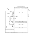
図4ないし図7は、作用的にプリンタ66に連結される印刷後の仕上げ装置64に取り付けられたモジュラー被覆装置62を例示する。図5は、被覆装置62の拡大図であり、図6は、被覆装置62の融着器/冷却器モジュール68の詳細図である。図4ないし図7を参照すると、モジューラ被覆装置62は、各シート42の上部に被覆を施すための構成要素を有する上部モジュール68、および各シート42の下部に被覆を施すための構成要素を有する下部モジュール70を有する。2つの印刷媒体通路は、印刷後の仕上げ装置64を通して設けられている。被覆媒体通路44は、被覆モジュール68および70を通って走行し、バイパス媒体通路45は、被覆モジュール68および70を迂回している。両媒体通路44および45は、シート42を(図7に示される)出力トレイ72または他の下流側仕上げ工程に対して排出する。
FIGS. 4-7 illustrate a
上部モジュール68は、第1/上部の被覆材料ウェブ供給スプール12、第1/上部のウェブ巻き取りスプール14、ならびに第1/上部の融着器および冷却器ユニット74を有する。下部モジュール70は、第2/下部の被覆材料ウェブ供給スプール16、第2/下部のウェブ巻き取りスプール18、ならびに第2/下部の融着器および冷却器ユニット76を有する。第1/上部の被覆材料ウェブ20は、図5に示されるように、上部供給スプール12から融着器および冷却ユニット74を通って上部巻き取りスプール14まで、アイドラーローラ78および80を周って走行する。第2/下部の被覆材料ウェブ24は、下部ウェブ供給スプール16から融着器および冷却器ユニット76を通って下部ウェブ巻き取りスプール18まで、アイドラーローラ82および84を周って走行する。上部供給および巻き取りスプール12および14、ならびに下部供給および巻き取りスプール16および18は、互いに重なって配置され、垂直方向にコンパクトな設計を成し遂げている。各融着器および冷却器ユニットでは被覆材料ウェブの走行に沿って融着器、冷却器の順で配置されている。
The
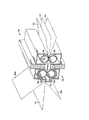
出口駆動ローラ86および係合するピンチローラ88は、被覆装置62から媒体シート42を出力トレイ72まで前進させる。上部被覆モジュール68内のローラのそれぞれは、上部モジュールフレーム90に搭載されるか、または上部モジュールフレーム90に支持される。下部被覆モジュール70内のローラのそれぞれは、下部モジュールフレーム92に搭載されるか、または下部モジュールフレーム92に支持される。図8は、上部モジュール68の斜視図である。モジュール68およびそれに対応する下部モジュール70は、印刷後の仕上げ装置64の内外に摺動し、モジュールの取り付け、修理、および交換を容易にするように構成されている。
The
被覆装置62の様々な構成要素は、構成要素をフレームに直接搭載するなどによってフレームに直接支持され得るか、または構成要素は、構成要素を支持構造体またはフレームに搭載された他の構成要素に搭載するなどによってフレームに間接的に支持され得る。構成要素を支持するフレームは、上部モジュールフレーム90および下部モジュールフレーム92におけるようなモジュールフレーム、全体的な被覆装置フレーム、または仕上げ装置の内外に摺動するモジュラーユニットで被覆装置が構築されていない場合のような印刷後の仕上げ装置フレームであり得る。
The various components of the
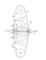
図9は、モジュラー被覆装置62の従動構成要素用の駆動列を例示する。図9に示される駆動列では、媒体通路44ならびにウェブ通路46および48における主な構成要素はすべて、1つのモータによって駆動される。他の駆動列構成が可能であり、2つ以上のモータを、様々な構成要素を駆動するために用いることができる。図9を参照すると、主要駆動ステッパモータ94は、主要駆動ギア96を時計回りに駆動する。下部ウェブ巻き取りスプール18に連結された下部ウェブ巻き取りギア98は、スペーサギア100を通して主要ギア96から時計回りに駆動される。上部ウェブ巻き取りスプール14に連結された上部ウェブ巻き取りギア102は、一対の反転スペーサギア104および106を通して主要ギア96から反時計回りに駆動される。出口駆動ローラ86に連結された出口駆動ギア108は、主要ギア96から直接反時計回りに駆動される。
FIG. 9 illustrates a drive train for the driven components of the
主要ギア96と同軸上で回転する中央駆動ギア110は、モータ94の付勢で時計回りに駆動される。上部融着ローラ34に連結された上部融着ローラギア112、および上部冷却ローラ56に連結された上部冷却ローラギア114は、中央駆動ギア110から反時計回りに駆動される。下部融着ローラ36に連結された下部融着ローラギア116、および下部冷却ローラ58に連結された下部冷却ローラギア118は、中央スペーサギア120を通して、中央駆動ギア110から時計回りに駆動される。
The
図示されていないが、図9に例示される駆動列はまた、可動部品間の適切な関係を維持するために必要であるかまたは望ましい場合に、いくつかの駆動要素間に介在するクラッチを含み得る。たとえば、電磁スリップクラッチは、上部および下部被覆ウェブ20、20aおよび24、24aへの張力を制御するのを助けるために、巻き取りギア98および102に含まれなければならない。
Although not shown, the drive train illustrated in FIG. 9 also includes a clutch interposed between several drive elements, if necessary or desirable to maintain the proper relationship between the moving parts. obtain. For example, an electromagnetic slip clutch must be included in the take-up gears 98 and 102 to help control the tension on the upper and
上記の例示的な実施形態を参照しながら本発明を示し記載したが、他の形状、詳細、および実施形態が、添付の特許請求の範囲において定義される本発明の趣旨および範囲を逸脱せずになされ得ることを理解されたい。 Although the invention has been shown and described with reference to the above exemplary embodiments, other shapes, details, and embodiments do not depart from the spirit and scope of the invention as defined in the appended claims. It should be understood that
印刷装置や印刷装置に関連して用いられる仕上げ装置に実施して至便である。 It is convenient to carry out the present invention on a printing device or a finishing device used in connection with the printing device.
10 印刷媒体被覆装置
12、16 ウェブ供給部
14、18 ウェブ巻き取り部
20、24 第2の被覆材料ウェブ
22 融着器
40 融着器ニップ
42 印刷媒体
44 媒体通路
50 冷却器
52,54 剥離棒
90、92 フレーム
94 モータ
DESCRIPTION OF
Claims (10)
第1のウェブ供給部と、
第1のウェブ巻き取り部と、
第2のウェブ供給部と、
第2のウェブ巻き取り部と、
通過する媒体通路を画定する融着器とを備え、
前記第1のウェブ供給部および第1のウェブ巻き取り部は、前記媒体通路の一方の側に配置され、前記第2のウェブ供給部および前記第2のウェブ巻き取り部は、前記第1のウェブ供給部および前記第1のウェブ巻き取り部とは反対側にある前記媒体通路の他方の側に配置されるとともに、さらに
前記媒体通路に沿って前記融着器を通って、前記第1のウェブ供給部から前記第1のウェブ巻き取り部まで走行する第1の被覆材料ウェブと、
前記媒体通路に沿って前記融着器を通って、前記第2のウェブ供給部から前記第2のウェブ巻き取り部まで走行する第2の被覆材料ウェブとを備えることを特徴とする印刷媒体被覆装置。 An apparatus for coating a print medium, comprising:
A first web supply unit;
A first web take-up unit;
A second web supply,
A second web take-up unit;
A fuser defining a medium passage therethrough;
The first web supply and the first web take-up are located on one side of the media path, and the second web supply and the second web take-up are the first web take-up and the first web take-up. The first web take-up unit is disposed on the other side of the medium passage opposite to the first web take-up unit, and further through the fuser along the medium passage, A first coating material web traveling from a web supply to the first web take-up,
A second web of coating material traveling from the second web supply to the second web take-up along the fuser along the media path. apparatus.
フレームと、
媒体通路の第1の側に近接して前記フレームによって回転可能に支持された第1のウェブ供給スプールと、
前記第1の供給スプールから始まり、第1のウェブ巻き取りスプールで終わる第1のウェブ通路に沿って、前記第1のウェブ供給スプールから下流側に前記媒体通路の前記第1の側に近接して前記フレームによって回転可能に支持された第1のウェブ巻き取りスプールと、
前記第1の側とは反対側にある媒体通路の第2の側に近接して前記フレームによって回転可能に支持された第2のウェブ供給スプールと、
該第2の供給スプールから始まり、第2のウェブ巻き取りスプールで終わる第2のウェブ通路に沿って前記第2のウェブ供給スプールから下流側に前記媒体通路(44)の前記第2の側に近接して前記フレームによって回転可能に支持された第2のウェブ巻き取りスプールと、
前記媒体通路、前記第1の供給スプールと前記第1の巻き取りスプールとの間の前記第1のウェブ通路、および前記第2の供給スプールと前記第2の巻き取りスプールとの間の前記第2のウェブ通路に沿って配置された、前記フレームによって支持される融着器と、
前記第1のウェブ巻き取りスプールおよび前記第2のウェブ巻き取りスプールを駆動するように連結されるモータとを備え、
前記媒体通路、前記第1のウェブ通路、および前記第2のウェブ通路は、前記融着器を通って互いに符合していることを特徴とする印刷媒体被覆装置。 An apparatus for coating a print medium, comprising:
Frame and
A first web supply spool rotatably supported by the frame proximate a first side of the media passage;
Along a first web path starting from the first supply spool and ending with a first web take-up spool, downstream from the first web supply spool and proximate to the first side of the media path. A first web take-up spool rotatably supported by the frame.
A second web supply spool rotatably supported by the frame proximate a second side of the media passage opposite the first side;
Along a second web path starting from the second supply spool and ending with a second web take-up spool downstream from the second web supply spool to the second side of the media path (44). A second web take-up spool proximately rotatably supported by the frame;
The media path, the first web path between the first supply spool and the first take-up spool, and the first web path between the second supply spool and the second take-up spool. A fuser supported by the frame, the fuser being disposed along two web paths;
A motor coupled to drive the first web take-up spool and the second web take-up spool;
The print media coating apparatus of claim 1, wherein the media passage, the first web passage, and the second web passage coincide with each other through the fuser.
該被覆材料ウェブの各々は、被覆材料の層を含む、前記融着器から上流側の第1の部分と、実質的にすべての前記被覆材料が除去された前記融着器(22)から下流側の第2の使用済み部分とを有することを特徴とする請求項2に記載の装置。 A web of coating material running from each of the web supply spools along each of the web paths to a corresponding web take-up spool;
Each of the coating material webs includes a first portion upstream from the fuser that includes a layer of coating material and a downstream portion from the fuser (22) with substantially all of the coating material removed. 3. A device according to claim 2, comprising a second used part on the side.
前記融着器から下流側に前記媒体通路に沿って配置され、前記第2のウェブ通路内に突出する、前記フレームによって支持された第2の剥離棒とをさらに備え、
前記媒体通路、前記第1のウェブ通路、および前記第2のウェブ通路は、前記融着器から前記第1、第2の剥離棒の少なくとも1つまで、互いに符合していることを特徴とする請求項2に記載の装置。 A first release rod supported by the frame, disposed along the media path downstream from the fuser and projecting into the first web path;
A second release rod supported by the frame, disposed along the medium path downstream from the fuser and projecting into the second web path;
The medium passage, the first web passage, and the second web passage are coincident with each other from the fuser to at least one of the first and second peel bars. An apparatus according to claim 2.
媒体通路の第1の側に近接した第1の回転可能なウェブ供給スプールと、
該第1のウェブ供給スプールで始まり、第1の回転可能なウェブ巻き取りスプールで終わる第1のウェブ通路に沿って前記第1のウェブ供給スプールから下流側で前記媒体通路の前記第1の側に近接した第1の回転可能なウェブ巻き取りスプールと、
前記第1の側とは反対側にある前記媒体通路の第2の側に近接した第2の回転可能なウェブ供給スプールと、
該第2のウェブ供給スプールで始まり、第2の回転可能なウェブ巻き取りスプールで終わる第2のウェブ通路に沿って前記第2のウェブ供給スプールから下流側で前記媒体通路の前記第2の側に近接した第2の回転可能なウェブ巻き取りスプールと、
前記第1の供給スプールと前記第1の巻き取りスプールとの間の前記第1のウェブ通路および前記第2の供給スプールと前記第2の巻き取りスプールとの間の前記第2のウェブ通路に沿った融着器であって、互いに係合可能で、融着器ニップを形成する第1および第2のローラを備え、前記融着器ニップは、該融着器を通過する前記媒体通路を画定する融着器と、
前記第1のウェブ巻き取りスプール、前記第2のウェブ巻き取りスプール、および前記融着ローラの少なくとも1つを駆動するように連結される単一のモータとを備え、
前記媒体通路、前記第1のウェブ通路、および前記第2のウェブ通路は、前記融着器を通して互いに符合していることを特徴とする印刷媒体被覆装置。 A print media coating device,
A first rotatable web supply spool proximate a first side of the media passage;
The first side of the media path downstream from the first web supply spool along a first web path beginning with the first web supply spool and ending with a first rotatable web take-up spool A first rotatable web take-up spool proximate to;
A second rotatable web supply spool proximate a second side of the media passage opposite the first side;
The second side of the media path downstream from the second web supply spool along a second web path beginning with the second web supply spool and ending with a second rotatable web take-up spool A second rotatable web take-up spool proximate to
The first web path between the first supply spool and the first take-up spool and the second web path between the second supply spool and the second take-up spool; A first fuser and a second roller that are engageable with each other and form a fuser nip, wherein the fuser nip extends through the media passage through the fuser. A fuser to define;
A single motor coupled to drive at least one of the first web take-up spool, the second web take-up spool, and the fusing roller;
The print media coating apparatus according to claim 1, wherein the medium passage, the first web passage, and the second web passage coincide with each other through the fuser.
該主要駆動ギアと同軸上に搭載された中央駆動ギアと、
前記主要駆動ギアと係合する第1のウェブ巻き取りスペーサギアと、
該第1のウェブ巻き取りスペーサギアと係合する、前記第1のウェブ巻き取りスプールに連結された第1のウェブ巻き取りギアと、
前記第2のウェブ巻き取りスプールに連結された第2のウェブ巻き取りギアと、
互いに係合する第1および第2の反転スペーサギアであって、該第1の反転スペーサギアは前記主要駆動ギアと係合し、該第2の反転スペーサギアは前記第2のウェブ巻き取りギアと係合する第1および第2のスペーサギアと、
前記中央駆動ギアと係合する、前記第1の融着ローラと連結された第1の融着ギアと、
前記中央駆動ギアと係合する融着スペーサギアと、
該融着スペーサギアと係合する、前記第2の融着ローラと連結された第2の融着ギアとをさらに備えることを特徴とする請求項5に記載の装置。 A main drive gear directly coupled to drive the motor;
A central drive gear mounted coaxially with the main drive gear;
A first web take-up spacer gear engaged with the main drive gear;
A first web take-up gear coupled to the first web take-up spool for engaging the first web take-up spacer gear;
A second web take-up gear connected to the second web take-up spool;
First and second reversing spacer gears engaged with each other, the first reversing spacer gears engaging with the main drive gear, and the second reversing spacer gears engaging the second web take-up gear; First and second spacer gears engaging with
A first fusing gear coupled to the first fusing roller, the first fusing gear engaging the central drive gear;
A fused spacer gear engaged with the central drive gear;
The apparatus of claim 5, further comprising a second fusing gear coupled to the second fusing roller, the second fusing gear engaging the fusing spacer gear.
媒体通路の第1の側に近接した第1のウェブ搬送システムと、
前記第1の側とは反対側にある前記媒体通路の第2の側に近接した第2のウェブ搬送システムと、
前記第1のウェブ搬送システムと前記第2のウェブ搬送システムとの間で前記媒体通路に沿って動作する融着器と、
を備える印刷媒体被覆装置。 An apparatus for coating a print medium, comprising:
A first web transport system proximate a first side of the media path;
A second web transport system proximate a second side of the media path opposite the first side;
A fuser operating along the media path between the first web transport system and the second web transport system;
A printing medium coating device comprising:
前記印刷媒体の一方の側に被覆を施す工程と、
前記印刷媒体の他方の側に被覆を同時に施す工程とを含む印刷媒体被覆方法。 A method for applying a coating to a print medium, comprising:
Applying a coating on one side of the print medium;
Simultaneously applying a coating to the other side of the print medium.
被覆材料の2つの層の間に前記印刷媒体を挟む工程と、
前記印刷媒体に前記被覆材料を融着させる工程とを含む印刷媒体被覆方法。 A method of coating a print medium, comprising:
Sandwiching the print medium between two layers of coating material;
Fusing the coating material to the print medium.
それぞれが被覆材料と該被覆材料を担持する担体とを有する第1および第2の被覆材料ウェブを提供する工程と、
前記印刷媒体を前記第1および第2の被覆材料ウェブの間に挟む工程と、
前記印刷媒体に前記被覆材料を融着させる工程と、
前記第1の被覆材料ウェブ上の前記被覆材料から前記担体を剥離し、前記第2の被覆材料ウェブ上の前記被覆材料から前記担体を剥離する工程とを含む印刷媒体被覆方法。 A method for applying a coating to a print medium, comprising:
Providing first and second webs of coating material each having a coating material and a carrier carrying the coating material;
Sandwiching the print medium between the first and second webs of coating material;
Fusing the coating material to the print medium;
Stripping the carrier from the coating material on the first web of coating material and stripping the carrier from the coating material on the second web of coating material.
Applications Claiming Priority (1)
| Application Number | Priority Date | Filing Date | Title |
|---|---|---|---|
| US10/280,989 US6823920B2 (en) | 2002-10-25 | 2002-10-25 | Print media coating device and method |
Publications (2)
| Publication Number | Publication Date |
|---|---|
| JP2004142942A true JP2004142942A (en) | 2004-05-20 |
| JP2004142942A5 JP2004142942A5 (en) | 2006-09-07 |
Family
ID=32107079
Family Applications (1)
| Application Number | Title | Priority Date | Filing Date |
|---|---|---|---|
| JP2003326235A Withdrawn JP2004142942A (en) | 2002-10-25 | 2003-09-18 | Print media coating apparatus and print media coating method |
Country Status (2)
| Country | Link |
|---|---|
| US (1) | US6823920B2 (en) |
| JP (1) | JP2004142942A (en) |
Cited By (1)
| Publication number | Priority date | Publication date | Assignee | Title |
|---|---|---|---|---|
| JP2013043406A (en) * | 2011-08-25 | 2013-03-04 | Sharp Corp | Image forming apparatus, processing unit, and image forming method |
Families Citing this family (4)
| Publication number | Priority date | Publication date | Assignee | Title |
|---|---|---|---|---|
| JP3903382B2 (en) * | 2002-12-10 | 2007-04-11 | 三井金属鉱業株式会社 | Spacer winding device in processing device for film carrier tape for electronic component mounting |
| KR101857288B1 (en) * | 2011-08-26 | 2018-05-14 | 삼성디스플레이 주식회사 | Methods and apparatus for peeling a donor film from a substrate |
| KR101929527B1 (en) * | 2012-09-17 | 2018-12-17 | 삼성디스플레이 주식회사 | Film peeling apparatus |
| CN105966976A (en) * | 2016-06-17 | 2016-09-28 | 重庆鑫仕达包装设备有限公司 | Premixing-free solvent-free compound machine and grouping pre-coating solvent-free compound method |
Family Cites Families (7)
| Publication number | Priority date | Publication date | Assignee | Title |
|---|---|---|---|---|
| US3415705A (en) * | 1964-12-30 | 1968-12-10 | Vitta Corp | Machines for tape transfer |
| US3547730A (en) * | 1966-12-16 | 1970-12-15 | Du Pont | Machine for making resist images |
| JPS6151391A (en) * | 1984-08-20 | 1986-03-13 | Toshiba Corp | Thermal transfer recording medium and its apparatus |
| US5370960A (en) * | 1993-04-02 | 1994-12-06 | Rexham Graphics Incorporated | Electrographic imaging process |
| US5571368A (en) * | 1994-04-15 | 1996-11-05 | Graphic Laminating, Inc. | Laminating machine with improved heating and cooling |
| US5582669A (en) * | 1994-05-10 | 1996-12-10 | Polaroid Corporation | Method for providing a protective overcoat on an image carrying medium utilizing a heated roller and a cooled roller |
| US5714305A (en) * | 1995-05-24 | 1998-02-03 | Polaroid Corporation | Overcoat-releasing laminate and method for the manufacture thereof |
-
2002
- 2002-10-25 US US10/280,989 patent/US6823920B2/en not_active Expired - Fee Related
-
2003
- 2003-09-18 JP JP2003326235A patent/JP2004142942A/en not_active Withdrawn
Cited By (2)
| Publication number | Priority date | Publication date | Assignee | Title |
|---|---|---|---|---|
| JP2013043406A (en) * | 2011-08-25 | 2013-03-04 | Sharp Corp | Image forming apparatus, processing unit, and image forming method |
| US9764919B2 (en) | 2011-08-25 | 2017-09-19 | Sharp Kabushiki Kaisha | Image forming apparatus, processing unit, and image forming method |
Also Published As
| Publication number | Publication date |
|---|---|
| US6823920B2 (en) | 2004-11-30 |
| US20040079475A1 (en) | 2004-04-29 |
Similar Documents
| Publication | Publication Date | Title |
|---|---|---|
| JP4605482B2 (en) | Glossiness imparting device and image forming system | |
| US20010026720A1 (en) | Laminator peel-off bar | |
| JP2004325934A (en) | Fixing device | |
| JP4080404B2 (en) | Printing media coating device | |
| JP5836631B2 (en) | Film cartridge for surface treatment equipment | |
| JP2004142942A (en) | Print media coating apparatus and print media coating method | |
| US6690908B1 (en) | Print media coating device and method | |
| JP2003312085A (en) | Laminator, printer and method for laminating printed recording medium | |
| JP2013024912A (en) | Recording material cooling and humidifying device, image forming apparatus, and image heating system | |
| JP2007304459A (en) | Image forming apparatus and image forming method | |
| US7508404B2 (en) | Thermal printer with two print heads | |
| US6802355B2 (en) | Overcoat application peel apparatus | |
| JP2011037042A (en) | Printing mechanism and thermal printer | |
| US11442382B2 (en) | Imaging system with gloss treatment device | |
| JP2022074735A (en) | Foil transfer apparatus | |
| JP2004142941A (en) | Print media coating apparatus and finishing apparatus | |
| JPS637953A (en) | Recording apparatus | |
| JPS63139753A (en) | Recorder | |
| JP2003107660A (en) | Image forming device | |
| JPS6351162A (en) | Recording apparatus | |
| JPH11224011A (en) | Fixing device | |
| JP2007216410A (en) | Printer | |
| JPS62261463A (en) | Recorder | |
| KR20050034522A (en) | Thermal type image forming apparatus and method thereof | |
| JP2004276269A (en) | Transfer method, transfer device, and recording apparatus |
Legal Events
| Date | Code | Title | Description |
|---|---|---|---|
| A521 | Request for written amendment filed |
Free format text: JAPANESE INTERMEDIATE CODE: A523 Effective date: 20060721 |
|
| A621 | Written request for application examination |
Free format text: JAPANESE INTERMEDIATE CODE: A621 Effective date: 20060721 |
|
| A761 | Written withdrawal of application |
Free format text: JAPANESE INTERMEDIATE CODE: A761 Effective date: 20080508 |