JP2004142436A - Print medium coating apparatus and print medium coating method - Google Patents
Print medium coating apparatus and print medium coating method Download PDFInfo
- Publication number
- JP2004142436A JP2004142436A JP2003326202A JP2003326202A JP2004142436A JP 2004142436 A JP2004142436 A JP 2004142436A JP 2003326202 A JP2003326202 A JP 2003326202A JP 2003326202 A JP2003326202 A JP 2003326202A JP 2004142436 A JP2004142436 A JP 2004142436A
- Authority
- JP
- Japan
- Prior art keywords
- web
- coating
- coating material
- cooler
- print medium
- Prior art date
- Legal status (The legal status is an assumption and is not a legal conclusion. Google has not performed a legal analysis and makes no representation as to the accuracy of the status listed.)
- Pending
Links
Images


Classifications
-
- B—PERFORMING OPERATIONS; TRANSPORTING
- B41—PRINTING; LINING MACHINES; TYPEWRITERS; STAMPS
- B41M—PRINTING, DUPLICATING, MARKING, OR COPYING PROCESSES; COLOUR PRINTING
- B41M7/00—After-treatment of prints, e.g. heating, irradiating, setting of the ink, protection of the printed stock
- B41M7/0027—After-treatment of prints, e.g. heating, irradiating, setting of the ink, protection of the printed stock using protective coatings or layers by lamination or by fusion of the coatings or layers
Landscapes
- Coating Apparatus (AREA)
- Laminated Bodies (AREA)
Abstract
Description
本発明は、印刷媒体に被覆を施すための印刷媒体被覆装置および印刷媒体被覆方法とに関する。 The present invention relates to a print medium coating apparatus and a print medium coating method for coating a print medium.
印刷された媒体に透明な可撓性材料の膜を被覆することが望まれる場合がある。このような被膜を、調合し、塗布して印刷された画像を保護し、印刷された画像を向上させるか、または(印刷された領域および印刷されていない領域の両方を含む)媒体全体にわたってより均一な光沢レベルを提供するのに役立つようにすることができる。被覆は、被覆材料を含む多層ウェブを媒体上に積層し、熱および圧力を加えて被覆材料を媒体に融着させることによって印刷媒体に施される。ウェブは、通常、被覆材料の膜/層、担体(裏打ちとも呼ばれる)、被覆材料と担体との間の解放層、および被覆材料が紙または他の印刷媒体に接着するを助ける被覆材料上の接着層を含む。 が あ る It may be desirable to coat the printed media with a film of a transparent flexible material. Such coatings may be formulated and applied to protect the printed image, enhance the printed image, or to provide more coverage across the media (including both printed and unprinted areas). It can help provide a uniform gloss level. The coating is applied to the print media by laminating a multilayer web containing the coating material on the media and applying heat and pressure to fuse the coating material to the media. The web typically comprises a film / layer of coating material, a carrier (also called a backing), a release layer between the coating material and the carrier, and an adhesive on the coating material that helps the coating material adhere to paper or other print media. Including layers.
図1に示されるような従来の片面被覆装置では、剥離バー2は、融着器4の下流の媒体通路3にわずかに突出し、被覆材料ウェブ5に圧力を加える。ウェブ5は、供給スプール6から巻き取りスプール7まで融着器4を通り抜ける。被覆材料ウェブ5および媒体シート8は、ウェブ5の被覆材料膜部分を印刷媒体シート8に向けて、融着器4を通して共に挟まれる。融着器4は、ウェブ/シート積層体に熱および圧力を加えて、接着層を溶融させ、被覆材料膜を印刷媒体に固着させ、解放層を軟化させる。ウェブ5の担体部分は、剥離バー2から巻き取りスプール7に向かって上向きに角度をなして離れる。剥離バー2によってウェブ5に加えられた点圧力は、ウェブ5の担体部分が、被覆膜からよりきれいに分離されるのに役立つ。
In a conventional single-side coating apparatus as shown in FIG. 1, the stripping bar 2 slightly projects into the
接着/被覆材料は、融着器4の下流に向かって冷却すると、硬化して印刷媒体に永久的に固着する。担体が被覆材料から離れて引き剥がされる前に、接着/被覆材料ができるだけ硬化することが望ましい。剥離前に接着/被覆材料が硬化すればするほど、接着/被覆材料はより良好に印刷媒体に接着し、剥離によって被覆と媒体との間の結合が乱されることは少ない。従来の被覆装置は、受動冷却のみを用いる。受動冷却では、所望の冷却を可能にするため、融着器と剥離棒との間の距離は十分に長く、ウェブの速度は十分に遅くなくてはならない。 When the adhesive / coating material cools downstream of the fuser 4, it hardens and permanently adheres to the print media. It is desirable that the adhesive / coating material cure as much as possible before the carrier is peeled away from the coating material. The more the bonding / coating material cures before peeling, the better the bonding / coating material adheres to the print media, and the less the peeling will disrupt the bond between the coating and the media. Conventional coating equipment uses only passive cooling. In passive cooling, the distance between the fuser and the release bar must be long enough and the web speed must be low enough to allow the desired cooling.
本発明の目的は印刷媒体の被覆工程を改良し被覆工程の所要時間を短縮し、被覆の質を高めることにある。 SUMMARY OF THE INVENTION It is an object of the present invention to improve the coating process of a print medium, reduce the time required for the coating process, and enhance the coating quality.
融着器と剥離棒との間のウェブを能動的に冷却することによって、剥離前に被覆材料結合部の硬化を促進するように、本発明の様々な実施形態が開発された。その結果、本発明の一実施形態は、ウェブ供給部、ウェブ巻き取り部、融着器、および融着器から媒体通路において下流にあるウェブ冷却器を含む印刷媒体被覆装置を対象とする。被覆材料ウェブは、媒体通路に沿って融着器および冷却器を通ってウェブ供給部からウェブ巻き取り部まで走行する。 Various embodiments of the present invention have been developed to facilitate the curing of the coating material bond prior to peeling by actively cooling the web between the fuser and the peel bar. As a result, one embodiment of the present invention is directed to a print media coating apparatus that includes a web supply, a web take-up, a fuser, and a web cooler downstream in the media path from the fuser. The coating material web travels along the media path through the fuser and cooler from the web supply to the web take-up.
本発明の他の実施形態は、印刷媒体に被覆材料を積層すること、被覆材料を印刷媒体に融着させること、融着後に、被覆材料を冷却することを含む、印刷媒体に被覆を施す被覆方法に関する。 Another embodiment of the present invention is a coating for applying a coating to a print medium, including laminating the coating material on the print medium, fusing the coating material to the print medium, and cooling the coating material after fusing. About the method.
本発明により、印刷媒体の被覆工程に要する時間が短縮され、また被覆の質も向上する。融着器と剥離棒との間の距離も比較的短く装置は小型となる。 According to the present invention, the time required for the step of coating the print medium is reduced, and the quality of the coating is improved. The distance between the fuser and the stripper is also relatively short, making the device compact.
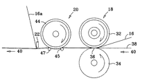
図3は、本発明の一実施形態による、印刷媒体シートに被覆を施す装置を例示する。図3を参照すると、被覆装置10は、被覆材料ウェブ供給スプール12およびウェブ巻き取りスプール14を有する。被覆材料ウェブ16は、供給スプール12から融着器18および冷却器20を通って、剥離棒22上を巻き取りスプール14まで走行する。ウェブ16は、通常、紙および他のタイプの印刷媒体と共に用いるのに適した被覆膜を搬送する任意のウェブを示す。
FIG. 3 illustrates an apparatus for coating a print media sheet according to one embodiment of the present invention. Referring to FIG. 3, the
図2は、被覆装置10において用いるのに適したウェブの一例を例示す断面図である。図2を参照すると、ウェブ16は、接着剤の層24、接着層24上の被覆材料の層26、担体28(または裏打ちとも呼ばれる)、および担体28と被覆材料の層26との間に介在する解放層30を有する。適当なウェブとしては、例えば、「有孔媒体に印刷され熱転写オーバーコートで被覆された画像(Images Printed On Porous Media And Coated With A Thermal Transfer Overcoat)」という名称で2002年6月11日に米国出願され本願出願人に譲渡された米国特許出願第10/167,891号の明細書に記載されている透明な可撓性のフィルムウェブが挙げられる。
FIG. 2 is a cross-sectional view illustrating an example of a web suitable for use in the
融着器18は、通常、ウェブ/媒体の積層体に熱もしくは圧力またはその両方を加えて被覆材料の層26を紙または他の印刷媒体に結合させる任意の適切な装置を示す。図3に例示される実施形態では、融着器18は、互いに回転して融着器ニップ36を形成する一対の対向するローラ32および34を有する。レーザ印刷装置において用いられるロール型定着器などの従来の定着器は、被覆装置10において融着器18として使用できるように適応させることができる。図3に示され、図5にさらに詳細に示されるこのような融着器の1つの例では、ローラ32は、加熱された融着器ローラとして構築され、ローラ34は、迎合(コンプライアント:compliant)加圧ローラとして構築されている。
紙または他の印刷媒体38の全幅にわたる被覆が所望されるとき、通常は、ウェブ16ならびに対応する供給部および巻き取りスプールは、図5に最もよく示されるように、印刷媒体とほぼ同じ幅である。印刷媒体シート38は、媒体通路40に沿って融着器18を通って移動する。ウェブ16は、供給スプール12から融着器18および冷却器20を通って、剥離棒22上をウェブ巻き取りスプール14まで、ウェブ通路42に沿って移動する。印刷媒体通路40およびウェブ通路42は、融着器ニップ36で集束し、融着器18および冷却器20を通って互いに符合し、次に、使用済みのウェブ16aが巻き取りスプール14に巻き取られる際に剥離棒22で分岐する。ウェブ16および媒体シート38が融着器ニップ36を通過する際にこれらに加えられる熱および圧力を組み合わせることによって、接着層24はシート38に溶融し、被覆材料の層26をシート38の上部に結合させ、解放層30を軟化させる。冷却器20は、ウェブ16およびシート38を冷却し、被覆材料の層26とシート38との間の結合部の硬化を促進する。硬化が促進されることにより、被覆材料の層26とシート38との間の結合は強くなり、担体28が剥離棒22において被覆材料の層26からよりきれいに分離されることが可能になる。スプール14に巻き取られた使用済みのウェブ16aは、担体28および解放層30の残物からなる。
When coating over the full width of the paper or
図3および図5の実施形態では、冷却器20は、互いに回転して冷却器ニップ48を形成する一対の対向するローラ44および46として構築される。冷却器20は、熱をウェブ16から逃すヒートシンクとして動作する。冷却ローラ44および46は、熱伝導材料の比較的大きな塊として構築され得る。この文脈において、「比較的大きい」とは、冷却ローラのサーマルマス(thermal mass)と、ウェブ/媒体積層体のサーマルマスとの間の関係を指す。あるいは、冷却ローラ44および46の一方または両方は、例えば、ローラを通して空気を循環させることによって、能動的に冷却され、所望のヒートシンクをウェブ16に提供することができる。冷却面接触面積を広げるため、ローラが回転することは望ましい。対向するローラは、同時に接触し、ウェブ/シート積層体の両側から熱を逃す。
3 and 5, the cooler 20 is constructed as a pair of
冷却器20の下流では、ウェブ16は、剥離棒22を通過する。剥離棒22は、ウェブ16の幅にわたって延在し、ウェブ通路42にわずかに突出する。ウェブ通路42は、とがった角度(好ましくは、60度〜130度)で剥離棒22において媒体通路40から分岐し、担体28が被覆材料の層26からよりきれいに引き剥がされるようにする。
下流 Downstream of the cooler 20, the
冷却器20に関連する様々な動作パラメータは、性能を最適化するために、必要または所望に応じて変更することができる。しかし、試験によると、融着ローラ32および34から50mm間隔を置き、剥離棒22から35mm間隔を置いた、2mm厚のアルミニウム壁を有する冷却ローラ44および46は、空気が冷却ローラ44および46を通して、直接ウェブ16にわたって吹き付けられるときに、所望の促進された冷却を提供することが示されている。
Various operating parameters associated with
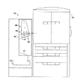
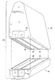
図4および図6は、印刷装置54に作用的に連結される印刷後の仕上げをする仕上げ装置52に取り付けられたモジュラー被覆装置50を例示する。図5は、被覆装置50の融着器/冷却器モジュール56の詳細図である。図4ないし図6を参照すると、モジュラー被覆装置50は、上部モジュール58および下部モジュール60を有する。2つの印刷媒体通路が仕上げ装置52を通して提供される。被覆媒体通路40は、被覆モジュール58および60を通って走行し、迂回媒体通路41は、被覆モジュール58および60を迂回する。媒体通路40および41は共に、シート38を出力トレイ62または他の下流仕上げ工程に対して排出する。
FIGS. 4 and 6 illustrate a
上部モジュール58は、ウェブ供給スプール12、ウェブ巻き取りスプール14、ならびに上部融着ローラおよび冷却ローラ32および44を収容する上部融着および冷却ユニット64を有する。下部モジュール60は、下部融着ローラおよび冷却ローラ34および46を収容する下部融着および冷却ユニット66を有する。ウェブ16は、供給スプール12から融着および冷却ユニット64を通って、遊びローラ68および70を周って巻き取りスプール14まで走行する。出口駆動ローラ72および関連のピンチローラ74は、被覆装置50から媒体シート38を出力トレイ62に向けて前進させる。上部被覆モジュール58内のローラはそれぞれ、上部モジュールフレーム76に搭載されるかまたは支持される。下部被覆モジュール60におけるローラはそれぞれ、下部モジュールフレーム78に搭載されるかまたは支持される。
The
被覆装置50の様々な構成要素は、構成要素をフレームに直接搭載するなどによってフレームに直接支持してよいし、あるいは構成要素は、構成要素を支持構造体またはフレームに搭載された他の構成要素に搭載するなどによってフレームに間接的に支持されてもよい。構成要素を支持するフレームは、上部モジュールフレーム76および下部モジュールフレーム78におけるようなモジュールフレーム、全体的な被覆装置フレーム、または被覆装置が仕上げ装置内外へ摺動するモジュラーユニットで構築されていない場合のような仕上げ装置フレームであり得る。
The various components of the
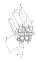
図7は、仕上げ装置52内外へ摺動し、各モジュールの取り付け、修理、および交換を容易にするように構成された上部モジュール58および下部モジュール60の斜視図である。
FIG. 7 is a perspective view of
図8は、モジュラー被覆装置50の従動構成要素用の駆動列を例示する。図8に示される駆動列では、媒体通路40ならびにウェブ通路42(図8には図示せず)における主な構成要素はすべて、1つのモータによって駆動される。他の駆動列構成が可能であり、2つ以上のモータが、様々な構成要素を駆動するために用いられ得る。図8を参照すると、主要駆動ステッパモータ80は、主要駆動ギア82を時計回りに駆動する。ウェブ巻き取りスプール14に連結されたウェブ巻き取りギア84は、一対の反転スペーサギア86および88を通して主ギア82から反時計回りに駆動される。出口駆動ローラ72に連結された出口駆動ギア90は、主ギア82から直接反時計回りに駆動される。
FIG. 8 illustrates the drive train for the driven components of the
主ギア82と同軸上で回転する中央駆動ギア92は、モータ80の付勢で時計回りに駆動される。上部融着ローラ32に連結された上部融着ローラギア94、および上部冷却ローラ44に連結された上部冷却ローラギア96は、中央駆動ギア92から反時計回りに駆動される。下部融着ローラ34に連結された下部融着ローラギア98、および下部冷却ローラ46に連結された下部冷却ローラギア100は、中央スペーサギア102を通して、中央駆動ギア92から時計回りに駆動される。
中央 The
図示されていないが、図8に例示される駆動列はまた、可動部品の適切な関係を維持するために必要であるかまたは望ましい場合に、いくつかの駆動素子間に介在するクラッチを含み得る。例えば、電磁スリップクラッチは、被覆ェブ16および16aへの張力を制御するのを助けるために、巻き取りギア84に含まれなければならない。
Although not shown, the drive train illustrated in FIG. 8 may also include a clutch interposed between several drive elements if necessary or desirable to maintain the proper relationship of moving parts. . For example, an electromagnetic slip clutch must be included in the take-
図9に例示される冷却器20の代替実施形態では、上部および下部冷却ローラ44および46は、互いにオフセットし、ウェブ/媒体積層体が各ローラの周囲を部分的に包んで、冷却表面の接触面積を増加させるようになっている。
In an alternative embodiment of the cooler 20 illustrated in FIG. 9, the upper and
図10に例示される冷却器20の代替実施形態では、単一の冷却ローラ44は、ローラ44の反対側に隣接して位置する一対の遊びローラ45および47と連動して用いられる。遊びローラ45および47は、ローラ44に対してウェブ/媒体積層体を保持し、ウェブ/媒体積層体がローラ44を部分的に包み、冷却表面の接触面積を増加させるようになっている。
In an alternative embodiment of the cooler 20 illustrated in FIG. 10, a
図11に例示される冷却器20の代替実施形態では、冷却空気は、チャネル104を通してウェブ/媒体積層体にわたって吹き付けられる。
代替 In an alternative embodiment of the cooler 20 illustrated in FIG. 11, cooling air is blown through the
上記の例示的な実施形態を参照しながら本発明を示し記載したが、他の形状、詳細、および実施形態が、添付の特許請求の範囲において定義される本発明の趣旨および範囲を逸脱せずになされ得ることを理解されたい。 Although the invention has been shown and described with reference to the above exemplary embodiments, other shapes, details, and embodiments do not depart from the spirit and scope of the invention as defined in the appended claims. It should be understood that
印刷装置や印刷装置に関連して用いられる仕上げ装置に実施して至便である。 It is convenient to carry out the present invention on a printing device or a finishing device used in connection with the printing device.
10 被覆装置
12 ウェブ供給部(ウェブ供給スプール)
14 ウェブ巻き取り部(ウェブ巻き取りスプール)
16 被覆材料ウェブ
18 融着器
20 冷却器
22 剥離棒
38 印刷媒体
40 媒体通路
42 ウェブ通路
45,47 遊びローラ
50 モジュラー被覆装置
52 印刷後の仕上げ装置
54 印刷装置
104 チャネル
10
14 Web take-up part (web take-up spool)
16
Claims (10)
ウェブ供給部と、
ウェブ巻き取り部と、
通過する媒体通路を画定する融着器と、
該融着器の下流において、通過する前記媒体通路を画定するウェブ冷却器と、
前記ウェブ供給部から、前記媒体通路に沿って前記融着器および前記冷却器を通って、前記ウェブ巻き取り部まで走行する被覆材料ウェブと、
を備える印刷媒体被覆装置。 An apparatus for applying a coating to a print medium, comprising:
A web supply unit,
A web take-up unit,
A fuser defining a media passage therethrough;
Downstream of the fuser, a web cooler defining the media passage therethrough;
A coating material web running from the web supply to the web take-up along the fuser and cooler along the media path;
A printing medium coating device comprising:
媒体通路に近接した回転可能なウェブ供給スプールと、
該ウェブ供給スプールで始まり、ウェブ巻き取りスプールで終わるウェブ通路に沿って前記ウェブ供給スプールの下流で前記媒体通路に近接した回転可能な該ウェブ巻き取りスプールと、
前記供給スプールと前記巻き取りスプールとの間の前記媒体通路および前記ウェブ通路に沿って配置された融着器と、
前記融着器と前記巻き取りスプールとの間で前記媒体通路に沿って配置された冷却器とを備え、
前記媒体通路および前記ウェブ通路は、前記融着器および前記冷却器を通って互いに符合することを特徴とする印刷媒体被覆装置。 An apparatus for applying a coating to a print medium, comprising:
A rotatable web supply spool proximate the media path;
A rotatable web take-up spool proximate to the media path downstream of the web supply spool along a web path starting at the web supply spool and ending at a web take-up spool;
A fuser disposed along the media path and the web path between the supply spool and the take-up spool;
A cooler disposed along the medium path between the fuser and the take-up spool;
The print medium coating apparatus according to claim 1, wherein the medium passage and the web passage coincide with each other through the fuser and the cooler.
媒体通路に近接した被覆材料ウェブ搬送システムと、
前記媒体通路に沿って動作する融着器と、
該融着器の下流の前記媒体通路に沿って動作する冷却器とを備えることを特徴とする印刷媒体被覆装置。 An apparatus for applying a coating to a print medium, comprising:
A coating material web transport system proximate to the media path;
A fuser operating along the media path;
A cooler operating along the media path downstream of the fuser.
前記印刷媒体に被覆材料を積層させる工程と、
前記被覆材料を前記印刷媒体に融着させる工程と、
該融着させることの後で、前記被覆材料を冷却する工程とを含む印刷媒体被覆方法。 A method for applying a coating to a print medium, comprising:
Laminating a coating material on the print medium,
Fusing the coating material to the print medium;
Cooling said coating material after said fusing.
被覆材料および前記被覆材料を搬送する担体を有する被覆材料ウェブを提供する工程と、
前記印刷媒体に前記被覆材料ウェブを積層する工程と、
前記被覆材料を前記印刷媒体に融着する工程と、
前記被覆材料を冷却する工程と、
前記担体を前記被覆材料から剥離する工程と、
を含む印刷媒体被覆方法。 A method for applying a coating to a print medium, comprising:
Providing a coating material web having a coating material and a carrier that carries the coating material;
Laminating the coating material web on the print medium;
Fusing the coating material to the print medium;
Cooling the coating material;
Stripping the carrier from the coating material;
A printing medium coating method comprising:
Applications Claiming Priority (1)
| Application Number | Priority Date | Filing Date | Title |
|---|---|---|---|
| US10/280,461 US6690908B1 (en) | 2002-10-25 | 2002-10-25 | Print media coating device and method |
Publications (2)
| Publication Number | Publication Date |
|---|---|
| JP2004142436A true JP2004142436A (en) | 2004-05-20 |
| JP2004142436A5 JP2004142436A5 (en) | 2005-06-02 |
Family
ID=30770726
Family Applications (1)
| Application Number | Title | Priority Date | Filing Date |
|---|---|---|---|
| JP2003326202A Pending JP2004142436A (en) | 2002-10-25 | 2003-09-18 | Print medium coating apparatus and print medium coating method |
Country Status (2)
| Country | Link |
|---|---|
| US (1) | US6690908B1 (en) |
| JP (1) | JP2004142436A (en) |
Cited By (1)
| Publication number | Priority date | Publication date | Assignee | Title |
|---|---|---|---|---|
| WO2011122499A1 (en) * | 2010-03-30 | 2011-10-06 | 日本板硝子株式会社 | Method for producing transfer body |
Families Citing this family (5)
| Publication number | Priority date | Publication date | Assignee | Title |
|---|---|---|---|---|
| JP2008107609A (en) * | 2006-10-26 | 2008-05-08 | Ricoh Co Ltd | Method and apparatus for forming image sheet |
| JP2008158357A (en) * | 2006-12-25 | 2008-07-10 | Ricoh Co Ltd | Electrophotographic type image forming apparatus |
| US11247488B2 (en) | 2019-03-08 | 2022-02-15 | Palo Alto Research Center Incorporated | Printer head for strand element printing |
| US11318757B2 (en) * | 2019-07-09 | 2022-05-03 | Xerox Corporation | Method and apparatus for digital dyeing of thread |
| US11897188B2 (en) | 2020-01-30 | 2024-02-13 | Xerox Corporation | Method and system for 3D printing on fabric |
Family Cites Families (6)
| Publication number | Priority date | Publication date | Assignee | Title |
|---|---|---|---|---|
| US3549447A (en) * | 1968-07-01 | 1970-12-22 | Xerox Corp | Imaging system |
| JPS6151391A (en) | 1984-08-20 | 1986-03-13 | Toshiba Corp | Thermal transfer recording medium and its apparatus |
| JP3156139B2 (en) * | 1992-03-05 | 2001-04-16 | コニカ株式会社 | Glossy image forming method |
| US5370960A (en) | 1993-04-02 | 1994-12-06 | Rexham Graphics Incorporated | Electrographic imaging process |
| US5582669A (en) | 1994-05-10 | 1996-12-10 | Polaroid Corporation | Method for providing a protective overcoat on an image carrying medium utilizing a heated roller and a cooled roller |
| US5714305A (en) | 1995-05-24 | 1998-02-03 | Polaroid Corporation | Overcoat-releasing laminate and method for the manufacture thereof |
-
2002
- 2002-10-25 US US10/280,461 patent/US6690908B1/en not_active Expired - Lifetime
-
2003
- 2003-09-18 JP JP2003326202A patent/JP2004142436A/en active Pending
Cited By (2)
| Publication number | Priority date | Publication date | Assignee | Title |
|---|---|---|---|---|
| WO2011122499A1 (en) * | 2010-03-30 | 2011-10-06 | 日本板硝子株式会社 | Method for producing transfer body |
| JP2011207618A (en) * | 2010-03-30 | 2011-10-20 | Nippon Sheet Glass Co Ltd | Method of manufacturing transfer body |
Also Published As
| Publication number | Publication date |
|---|---|
| US6690908B1 (en) | 2004-02-10 |
Similar Documents
| Publication | Publication Date | Title |
|---|---|---|
| TW594382B (en) | Transfer device and method for a photo-sensing layer | |
| US5518762A (en) | Method and apparatus for manufacturing linerless labels | |
| JP4605482B2 (en) | Glossiness imparting device and image forming system | |
| KR100420390B1 (en) | Device and method for lamination | |
| US20010026720A1 (en) | Laminator peel-off bar | |
| JP2004325934A (en) | Fixing device | |
| US5557388A (en) | Printing or copying machine having a cooling device for the recording substrate | |
| JP4080404B2 (en) | Printing media coating device | |
| JP2002137294A (en) | Laminating equipment | |
| JP2004142436A (en) | Print medium coating apparatus and print medium coating method | |
| JP2004142942A (en) | Print media coating apparatus and print media coating method | |
| JP2003312085A (en) | Laminator, printer and method for laminating printed recording medium | |
| JP2004142943A5 (en) | Print media coating device | |
| JP2011046096A (en) | Recording device | |
| JP2007304459A (en) | Image forming apparatus and image forming method | |
| WO2004011263A9 (en) | Image recording device and imag recording method, and image receiving layer transfer element and image forming medium using them | |
| US20030121617A1 (en) | Overcoat application peel apparatus | |
| JP2004168475A (en) | Laminating apparatus | |
| US11442382B2 (en) | Imaging system with gloss treatment device | |
| JP2007011110A (en) | Image heating device | |
| JP2006142537A (en) | Covering apparatus | |
| JP3176287B2 (en) | Method and apparatus for removing hot-melt layer from laminated sheet | |
| JP2004276269A (en) | Transfer method, transfer device, and recording apparatus | |
| JP2002127623A (en) | Laminating device and image recording device | |
| JP2022074735A (en) | Foil transfer apparatus |
Legal Events
| Date | Code | Title | Description |
|---|---|---|---|
| A521 | Request for written amendment filed |
Free format text: JAPANESE INTERMEDIATE CODE: A523 Effective date: 20041008 |
|
| A621 | Written request for application examination |
Free format text: JAPANESE INTERMEDIATE CODE: A621 Effective date: 20041008 |
|
| A977 | Report on retrieval |
Free format text: JAPANESE INTERMEDIATE CODE: A971007 Effective date: 20070919 |
|
| A131 | Notification of reasons for refusal |
Free format text: JAPANESE INTERMEDIATE CODE: A131 Effective date: 20071002 |
|
| A521 | Request for written amendment filed |
Free format text: JAPANESE INTERMEDIATE CODE: A523 Effective date: 20071221 |
|
| A131 | Notification of reasons for refusal |
Free format text: JAPANESE INTERMEDIATE CODE: A131 Effective date: 20090407 |
|
| A02 | Decision of refusal |
Free format text: JAPANESE INTERMEDIATE CODE: A02 Effective date: 20091006 |