JP2004140145A - Aligner - Google Patents
Aligner Download PDFInfo
- Publication number
- JP2004140145A JP2004140145A JP2002302810A JP2002302810A JP2004140145A JP 2004140145 A JP2004140145 A JP 2004140145A JP 2002302810 A JP2002302810 A JP 2002302810A JP 2002302810 A JP2002302810 A JP 2002302810A JP 2004140145 A JP2004140145 A JP 2004140145A
- Authority
- JP
- Japan
- Prior art keywords
- axis
- stage
- axis direction
- counter mass
- wafer
- Prior art date
- Legal status (The legal status is an assumption and is not a legal conclusion. Google has not performed a legal analysis and makes no representation as to the accuracy of the status listed.)
- Withdrawn
Links
Images


Abstract
Description
【0001】
【発明の属する技術分野】
本発明は、露光装置に係り、更に詳しくは、半導体素子、液晶表示素子などの電子デバイスを製造するリソグラフィ工程で用いられる露光装置に関する。
【0002】
【従来の技術】
従来より、半導体素子、液晶表示素子等の製造におけるリソグラフィ工程では、種々の露光装置が用いられている。近年においては、ステップ・アンド・リピート方式の縮小投影露光装置(いわゆるステッパ)やステップ・アンド・スキャン方式の走査型投影露光装置(いわゆるスキャニング・ステッパ)などが比較的多く用いられている。
【0003】
この種の露光装置では、ウエハ上の複数のショット領域にマスクとしてのレチクルのパターンを転写する必要がある。このため、ウエハステージはXY2次元方向に例えばリニアモータ等を含む駆動装置により駆動されるが、このウエハステージの駆動によって生じる反力は、例えばステージと振動絶縁された基準(例えば床面又は装置の基準となるベースプレートなど)に設けられたフレーム部材を用いて機械的に床(大地)に逃がすことで処理していた(例えば、特許文献1参照)。
【0004】
また、例えば、スキャニング・ステッパの場合、ウエハステージのみならず、レチクルステージも所定の走査方向についてはリニアモータ等で駆動する必要があるが、このレチクルステージの駆動によって生じる反力の吸収のためには、主として運動量保存の法則を利用した走査方向一軸に関するカウンタマス機構が採用されている(例えば、特許文献2参照)。また、ウエハステージにカウンタステージ(カウンタマス)及びそのカウンタステージの位置を補正する補正装置(トリムモータなど)を備えた走査型露光装置も知られている(例えば、特許文献3参照)。この他、レチクルステージの移動により発生する反力を、フレーム部材を用いて機械的に基準、すなわち床(大地)に逃がすものもある(例えば、特許文献4参照)。
【0005】
【特許文献1】
特開平8−166475号公報
【特許文献2】
特開平8−63231号公報
【特許文献3】
特開2002−208562号公報
【特許文献4】
特開平8−330224号公報
【0006】
【発明が解決しようとする課題】
従来の投影露光装置では、基準に逃がされるステージの反力を防振台(除振台)等の振動絶縁装置で減衰させ、これによりその反力に起因する投影光学系(投影レンズ)の振動や基準を介した回り込みによるステージの振動が低減されていた。しかしながら、基準に逃がされたステージの反力は減衰させられたとはいえども、現状の微細加工において求められているレベルからみると、少なからず投影光学系や、ステージに振動を与えることになる。このため、ステージ(ひいては、ウエハ又はレチクル)を走査しつつ露光を行うスキャニング・ステッパにおいてはその反力に起因する振動が、露光精度を低下させる要因となる。
【0007】
これに対し、カウンタマス機構を用いて反力吸収を行う場合には反力の伝達をほぼ完全に防止することができるのであるが、従来のカウンタマス機構では、ステージの駆動方向と反対の方向にステージの駆動距離に比例した距離だけ移動するカウンタマスが用いられていた。このため、ステージの全ストロークに応じた(比例した)ストロークをカウンタマスについても用意しなければならず、露光装置の大型化を招く傾向があった。また、上記特許文献3に記載の露光装置のように、カウンタステージ及びそのカウンタステージの位置を補正する補正装置を備えた露光装置にあっては、補正装置によりカウンタステージの位置を補正できるので、カウンタステージのストロークを、補正装置を備えていない場合に比べて短くすることができる。また、上記特許文献3に記載の走査型露光装置では、振動の発生を防止することを主眼とし、いずれの動作に際してもカウンタステージの運動量保存則に従った移動を許容して、カウンタステージの移動により反力の完全吸収を図っている。また、上記特許文献3に記載の走査型露光装置では、カウンタステージの位置の補正は、もっぱら次の動作に際してカウンタステージのストロークを確保することを目的として行われている。しかしながら、例えば、ウエハに対する露光が終了してウエハステージがウエハ交換位置まで移動する場合などにおいて、カウンタステージの運動量保存則に従った移動を許容すると、その移動距離、すなわち露光終了時の位置からウエハ交換位置までの距離に応じたカウンタステージの大きなストロークを確保する必要があった。これでは、装置の大型化を効果的に抑制することは困難である。
【0008】
本発明は、かかる事情の下でなされたもので、その目的は、露光精度の低下を招くことなく、装置の大型化を抑制することが可能な露光装置を提供することにある。
【0009】
【課題を解決するための手段】
一般に、走査型露光装置では、振動を殆ど許容できない動作と、多少の振動を許容できる動作との両方が行われている。本発明は、この点に着目し、以下のような構成を採用する。
【0010】
請求項1に記載の発明は、マスク(R)と感光物体(W)とを第1軸方向に同期移動して前記マスクに形成されたパターンを前記感光物体上の複数の区画領域に順次転写する露光装置であって、前記マスクが載置されるマスクステージ(RST)と;前記感光物体が載置される物体ステージ(WST)と;前記マスクステージ及び物体ステージを駆動する駆動系(15、20、34)と;前記駆動系による前記物体ステージの駆動時に生じる反力の作用により運動量保存則に従って運動する少なくとも1つのカウンタマス(42A、42B、110)と;前記カウンタマスを駆動するカウンタマス駆動系(106A、106B、108A、108B等)と;前記カウンタマスの前記運動量保存則に従った運動を少なくとも一部相殺するように、前記駆動系による前記物体ステージの駆動状態に応じて前記カウンタマス駆動系を制御する制御装置(22)と;を備える露光装置である。
【0011】
これによれば、制御装置により、カウンタマスの運動量保存則に従った運動を少なくとも一部相殺するように、駆動系による物体ステージの駆動状態に応じてカウンタマス駆動系が制御される。この場合、制御装置は、露光に影響を与えない範囲で、かつ駆動系による物体ステージの駆動状態に応じてカウンタマス駆動系を制御することにより、カウンタマスの運動量保存則に従った運動の一部若しくは全部を相殺することができる。従って、物体ステージの駆動時の反力に起因するカウンタマスの運動量保存則に従った運動の際の移動ストロークを小さく設定できるので、露光装置のフットプリントの狭小化、あるいはカウンタマスの小型化が可能となり、いずれにしても露光精度の低下を招くことなく、装置の大型化を抑制することが可能となる。
【0012】
この場合において、請求項2に記載の露光装置の如く、前記制御装置は、第1軸方向に関する前記マスクステージと前記物体ステージとの加減速度がともに零となる前記マスクステージと前記物体ステージとの同期移動時を除く特定の時に、前記駆動系による前記物体ステージの駆動状態に応じた前記カウンタマス駆動系の制御を行うこととすることができる。
【0013】
この場合において、請求項3に記載の露光装置の如く、前記制御装置は、前記カウンタマス駆動系を介して、前記カウンタマスの前記運動量保存則に従った前記第1軸方向の運動及び前記カウンタマスの前記運動量保存則に従った前記第1軸方向に直交する第2軸方向の運動の少なくとも一方を、少なくとも一部相殺することとすることができる。
【0014】
上記請求項2及び3に記載の各露光装置において、請求項4に記載の露光装置の如く、前記特定の時は、前記感光物体上の任意の区画領域の露光終了後に、前記第1軸方向に関し前記マスクステージと前記物体ステージとを同時に減速する時を含むこととすることができる。
【0015】
上記請求項2及び3に記載の各露光装置において、請求項5に記載の露光装置の如く、前記特定の時は、感光物体の交換のための前記物体ステージの移動時、及び前記物体ステージ上の感光物体と前記マスクとの位置関係の計測のための前記物体ステージの移動時の少なくとも一方の時を含むこととすることができる。
【0016】
この場合において、請求項6に記載の露光装置の如く、前記制御装置は、前記感光物体の交換のための前記物体ステージの移動時、及び前記物体ステージ上の感光物体と前記マスクとの位置関係の計測のための前記物体ステージの移動時の少なくとも一方の時に、前記物体ステージの移動の間中、前記カウンタマス駆動系を介して前記カウンタマスを駆動し続けることとすることができる。
【0017】
上記請求項2及び3に記載の各露光装置において、請求項7に記載の露光装置の如く、前記特定の時は、前記感光物体上の2つの区画領域の露光の間における前記物体ステージの移動時の少なくとも一部を含むこととすることができる。
【0018】
請求項8に記載の発明は、マスク(R)と感光物体(W)とを第1軸方向に同期移動して前記マスクに形成されたパターンを前記感光物体上の複数の区画領域にステップ・アンド・スキャン方式で順次転写する露光装置であって、前記マスクが載置されるマスクステージ(RST)と;前記感光物体が載置される物体ステージ(WST)と;前記マスクステージ及び物体ステージを駆動する駆動系(15,20,34)と;前記駆動系による前記物体ステージの駆動時に生じる反力の作用により運動量保存則に従って運動する少なくとも1つのカウンタマス(42A,42B,110)と;前記カウンタマスを駆動するカウンタマス駆動系(106A,108A,106B,108B)と;前記ステップ・アンド・スキャン方式による前記複数の区画領域に対するパターンの転写動作シーケンス中に、前記転写動作シーケンスに要する時間と、前記物体ステージを含む可動部と前記カウンタマスとの質量比に応じて定まる前記転写動作シーケンス中の前記カウンタマスの前記運動量保存則に従った運動による定常変位とを考慮した少なくとも前記第1軸方向に関する平均速度が前記カウンタマスに与えられるように、前記カウンタマス駆動系を制御する制御装置(22)と;を備える露光装置である。
【0019】
これによれば、制御装置は、ステップ・アンド・スキャン方式による前記複数の区画領域に対するパターンの転写動作シーケンス中に、前記転写動作シーケンスに要する時間と、前記物体ステージを含む可動部と前記カウンタマスとの質量比に応じて定まる前記転写動作シーケンス中の前記カウンタマスの前記運動量保存則に従った運動による定常変位とを考慮した少なくとも前記第1軸方向(同期移動方向)に関する平均速度が前記カウンタマスに与えられるように、前記カウンタマス駆動系を制御する。このため、ステップ・アンド・スキャン方式による複数の区画領域に対するパターンの転写動作シーケンス中には、物体ステージの駆動に応じ、その駆動によって生じる反力の作用によってカウンタマスが運動量保存則にほぼ従った運動をし、例えば完全交互スキャンにて露光が行われる場合には、カウンタマスは第1軸方向に関して往復運動を繰り返しながら、一側から他側に徐々に移動する。しかるに、その転写動作シーケンスに要する時間と、物体ステージを含む可動部とカウンタマスとの質量比に応じて定まる転写動作シーケンス中のカウンタマスの運動量保存則に従った運動による定常変位とを考慮した第1軸方向に関する平均速度がカウンタマスに与えられるように、カウンタマス駆動系が制御されるので、そのカウンタマス駆動系の発生する力によりカウンタマスの前記定常変位が抑制される。従って、第1軸方向に関してはカウンタマスの移動ストロークを小さく設定することができる。また、ステップ・アンド・スキャン方式による複数の区画領域に対するパターンの転写動作シーケンスに要する時間は、通常数10秒という長い時間であるため、上記の定常変位をそのパターンの転写動作シーケンスに要する時間で割った平均速度は、小さく、その平均速度を与えるカウンタマス駆動系の駆動力は、露光中のカウンタマスの運動量保存則に従った運動を妨害するものではない。
【0020】
従って、マスクパターンと感光物体との重ね合わせ精度の低下を招くことがないとともに、露光装置のフットプリントの狭小化、あるいはカウンタマスの小型化が可能となり、いずれにしても露光精度の低下を招くことなく、装置の大型化を抑制することが可能となる。
【0021】
この場合において、請求項9に記載の露光装置の如く、前記制御装置は、前記パターンが転写される最初の区画領域と最後の区画領域との前記感光物体上における前記第1軸方向に直交する第2軸方向の位置が異なる場合には、前記転写動作シーケンス中に、前記転写動作シーケンスに要する時間と、前記可動部と前記カウンタマスとの質量比とに応じて定まる前記転写動作シーケンス中の前記カウンタマスの前記運動量保存則に従った運動による定常変位とを考慮した前記第2軸方向に関する平均速度が前記カウンタマスに与えられるように、前記カウンタマス駆動系を制御することとすることができる。
【0022】
上記請求項8及び9に記載の各露光装置において、請求項10に記載の露光装置の如く、前記駆動系は、前記物体ステージを前記第1軸方向に駆動する左右一組のモータを含み、前記カウンタマスは、前記各モータに個別に対応して設けられ、前記制御装置は、前記物体ステージの前記第2軸方向の位置に応じた各モータに対する推力配分を考慮して、前記転写動作シーケンス中、前記各カウンタマスを個別に制御することとすることができる。
【0023】
【発明の実施の形態】
《第1の実施形態》
以下、本発明の第1の実施形態を図1〜図9に基づいて説明する。図1には、第1の実施形態に係る露光装置100の概略構成が示されている。この露光装置100は、ステップ・アンド・スキャン方式の走査型露光装置、すなわち、いわゆるスキャニング・ステッパである。後述するように本実施形態では、投影光学系PLが設けられており、以下においては、この投影光学系PLの光軸AX方向をZ軸方向、これに直交する面内でマスクとしてのレチクルRと感光物体としてのウエハWとが相対走査される方向をY軸方向、これらZ軸及びY軸に直交する方向をX軸方向として説明を行う。
【0024】
この露光装置100は、照明系IOP、レチクルRを保持するマスクステージとしてのレチクルステージRST、投影光学系PL、ウエハWを保持してXY2次元方向に移動する物体ステージとしてのウエハステージWSTを有するウエハステージ装置11、及びこれらの制御系等を備えている。
【0025】
前記照明系IOPは、例えば、特開平9−320956号公報、特開平4−196513号公報などに開示されるように、光源ユニット、照度均一化光学系(オプティカルインテグレータを含む)、ビームスプリッタ、集光レンズ系、レチクルブラインド、及び結像レンズ系等(いずれも不図示)から構成され、照度分布のほぼ均一な露光用照明光(以下、単に「露光光」と呼ぶ)ELにより、レチクルR上の矩形(あるいは円弧状)の照明領域IARを均一な照度で照明する。ここで、露光光ELとしては、例えば、超高圧水銀ランプからの紫外域の輝線(g線、i線)や、KrFエキシマレーザ光(波長248nm)、ArFエキシマレーザ光(波長193nm)、F2レーザ光(波長157nm)などの遠紫外域、又は真空紫外域の光が用いられる。
【0026】
前記レチクルステージRSTは、後述する本体コラム10を構成する第2コラム12の天板14上に載置されている。この天板14は、レチクルベースとしての役割も果たしている。以下では、天板14を「レチクルベース14」とも記すものとする。
【0027】
レチクルステージRST上にはレチクルRが、例えば真空吸着により固定されている。レチクルステージRSTは、Z軸に垂直な平面内で2次元的に(X軸方向及びこれに直交するY軸方向及びXY平面に直交するZ軸回りの回転方向(θz方向)に)微少駆動可能に構成されている。
【0028】
また、このレチクルステージRSTは、レチクルベース14上をリニアモータ等で構成された駆動装置としてのレチクル駆動部15により、所定の走査方向(ここではY軸方向とする)に指定された走査速度で移動可能となっている。このレチクルステージRSTは、レチクルRの全面が少なくとも照明系IOPの光軸を横切ることができるだけの移動ストロークを有している。
【0029】
レチクルステージRST上にはレチクルレーザ干渉計(以下、「レチクル干渉計」という)16からのレーザビームを反射する移動鏡18が固定されており、レチクルステージRSTの移動面内の位置はレチクル干渉計16によって、例えば0.5〜1nm程度の分解能で常時検出される。ここで、実際には、レチクルステージRST上には走査方向(Y軸方向)に直交する反射面を有する移動鏡と非走査方向(X軸方向)に直交する反射面を有する移動鏡とが設けられ、これに対応してレチクル干渉計もレチクルX干渉計とレチクルY干渉計とが設けられているが、図1ではこれらが代表的に移動鏡18、レチクル干渉計16として示されている。なお、例えば、レチクルステージRSTの端面を鏡面加工して反射面(移動鏡18の反射面に相当)を形成しても良い。また、レチクルステージRSTの走査方向(本実施形態ではY軸方向)の位置検出に用いられるX軸方向に伸びた反射面の代わりに、少なくとも1つのレトロリフレクタを用いても良い。ここで、レチクルY干渉計とレチクルX干渉計の一方、例えばレチクルY干渉計は、測長軸を2軸有する2軸干渉計であり、このレチクルY干渉計の計測値に基づきレチクルステージRSTのY位置に加え、θz方向の回転も計測できるようになっている。
【0030】
レチクル干渉計16からのレチクルステージRSTの位置情報(又は速度情報)はステージ制御系20及びこれを介して主制御系22に送られ、ステージ制御系20では主制御系22からの指示に応じてレチクルステージRSTの位置情報に基づいてレチクル駆動部15を介してレチクルステージRSTを駆動する。
【0031】
前記本体コラム10は、クリーンルームの床面F上に複数(例えば3個)の防振ユニット24を介して設置された第1コラム26と、この第1コラム26上に設けられた第2コラム12とを備えている。
【0032】
第1コラム26は、各防振ユニット24の上部にそれぞれ直列に配置された複数本(例えば3本)の支柱28と、これらの支柱28によって水平に支持された鏡筒定盤30とから構成されている。この場合、前記防振ユニット24によって、床面Fから鏡筒定盤30を含む本体コラム10に伝達される微振動がマイクロGレベルで絶縁されるようになっている。
【0033】
前記第2コラム12は、第1コラム26の上面に固定された複数本(例えば3本)の脚部32と、これらの脚部32によって水平に支持された前記天板(レチクルベース)14とによって構成されている。
【0034】
前記投影光学系PLは、鏡筒定盤30の中央部に形成された不図示の開口内に上方から挿入され、その鏡筒部に設けられた不図示のフランジを介して鏡筒定盤30によって支持されている。投影光学系PLとしては、ここでは両側テレセントリックな縮小系であり、光軸AX方向(Z軸方向)に沿って所定間隔で配置された複数枚のレンズエレメントから成る屈折光学系が使用されている。この投影光学系PLの投影倍率は、例えば1/4、1/5あるいは1/6である。このため、照明系IOPからの露光光ELによってレチクルR上の照明領域IAR部分が照明されると、このレチクルRを通過した露光光ELにより、投影光学系PLを介してレチクルRの照明領域IAR内の回路パターンの縮小像(部分倒立像)が表面にフォトレジストが塗布されたウエハW上の照明領域IARに共役な露光領域IAに形成される。
【0035】
また、投影光学系PLの近傍には、オフアクシス(off−axis)方式のアライメント検出系ALGが設置されている。このアライメント検出系ALGとしては、例えば、ウエハ上のレジストを感光させないブロードバンドな検出光束を対象マークに照射し、その対象マークからの反射光により受光面に結像された対象マークの像と不図示の指標の像とを撮像素子(CCD)等を用いて撮像し、それらの撮像信号を出力する画像処理方式のFIA(Filed Image Alignment)系のアライメントセンサが用いられている。このアライメント検出系ALGの出力に基づき、後述する基準マーク板上の基準マーク及びウエハ上のアライメントマークのX、Y2次元方向の位置計測を行なうことが可能である。なお、FIA系に限らず、コヒーレントな検出光を対象マークに照射し、その対象マークから発生する散乱光又は回折光を検出したり、その対象マークから発生する2つの回折光(例えば同次数)を干渉させて検出したりするアライメントセンサを単独であるいは適宜組み合わせて用いることは勿論可能である。
【0036】
このアライメント検出系ALGからの情報は、不図示のアライメント制御装置によりA/D変換され、デジタル化された波形信号を演算処理してマーク位置が検出される。この結果が主制御系22に送られるようになっている。
【0037】
前記ウエハステージ装置11は、投影光学系PLの下方に配置されている。このウエハステージ装置11は、ウエハWを保持するウエハステージWST及び駆動装置としてのウエハ駆動装置34から構成されている。
【0038】
ウエハステージWSTは、図2に示されるX軸可動子112と、該X軸可動子112上に搭載された不図示のZ・チルト駆動機構と、該Z・チルト駆動機構によってZ軸方向及びXY面に対する傾斜方向に微小駆動可能に保持されたウエハテーブルTBとを含んで構成されている。なお、X軸可動子112及びZ・チルト駆動機構については更に後述する。
【0039】
前記ウエハテーブルTBの上面には、不図示のウエハホルダを介してウエハWが静電吸着又は真空吸着により固定されている。また、ウエハテーブルTB上には、前述のアライメント検出系ALGの検出中心から投影光学系PLの光軸までの距離を計測するベースライン計測のための基準マークを含む各種基準マークが形成された基準マーク板FMが固定されている。
【0040】
また、ウエハテーブルTBの上面には、図2に示されるように、X軸方向の一端(−X側端)にY軸方向に延びるX移動鏡36Xが設けられ、Y軸方向の一端(−Y側端)には、X軸方向に延びるY移動鏡36Yが設けられている。これらの移動鏡36X,36Yの外面側は、鏡面仕上げがなされた反射面となっている。なお、図1では、移動鏡36X,36Yが代表的に移動鏡36として示されている。なお、移動鏡36の代わりに、例えばウエハテーブルTBの端面を鏡面加工して反射面として用いても良い。
【0041】
これらの移動鏡36X,36Yの反射面と対向する位置には、X軸干渉計、Y軸干渉計(いずれも図示を省略)が設けられており、これらX軸干渉計、Y軸干渉計からのレーザビームが移動鏡36X,36Yの反射面に投射され、その反射光をそれぞれの干渉計が受光するようになっている。これにより、移動鏡36X,36Yそれぞれの反射面の基準位置からの変位を計測し、ウエハテーブルTB(ステージWST)の2次元位置が計測されるようになっている。なお、図1においては、X軸干渉計及びY軸干渉計が代表的にウエハ干渉計38として示されている。
【0042】
次に、前記ウエハ駆動装置34について、図2〜図7に基づいて、詳述する。
【0043】
このウエハ駆動装置34は、図2に示されるように、ウエハステージWSTをウエハ定盤40の上方でX軸方向に駆動するX軸リニアモータ装置(以下、「X軸モータ装置」と略す)XM、並びにウエハステージWST及びX軸モータ装置XMを駆動する第1Y軸リニアモータ装置(以下、「第1Y軸モータ装置」と略す)YMA及び第2Y軸リニアモータ装置(以下、「第2Y軸モータ装置」と略す)YMB等を備えている。
【0044】
ここで、第1Y軸モータ装置YMA(より詳しくは、後述するY軸固定子42A)は、ウエハベースBS上面の+X側のY軸方向一側(+Y側)及び他側(−Y側)の端部にそれぞれ固定された枠体44A及び46Aによって、Z軸方向及びX軸方向の動きが拘束された状態で非接触にて支持されている。また、第2Y軸モータ装置YMB(より詳しくは、後述するY軸固定子42B)は、ウエハベースBS上面の−X側のY軸方向一側(+Y側)及び他側(−Y側)の端部にそれぞれ固定された枠体46B及び44Bによって、Z軸方向及びX軸方向の動きが拘束された状態で非接触にて支持されている。
【0045】
前記第1Y軸モータ装置YMAは、図2及び図2中のウエハステージWST及びその駆動装置の一部を取り出し、その一部を破断して示す図3に示されるように、Y軸固定子42Aと、該Y軸固定子42Aに係合しつつ、Y軸固定子42Aに沿ってY軸方向に移動するY軸可動子48Aとを備えている。
【0046】
前記Y軸固定子48Aは、Y軸方向をその長手方向とし、XZ断面がコ字状(U字状)をした磁極ユニット50A、該磁極ユニット50Aの−Z側(下側)に設けられ、磁極ユニット50Aと同様の構造を有する磁極ユニット52A、磁極ユニット50A,52Aそれぞれの−X側に設けられ、Y軸方向をその長手方向とする板状のYガイド部材54A,56A、及び磁極ユニット50A,52A、Yガイド部材54A,56Aを所定の位置関係で保持する保持部材30A1,30A2を備えている。
【0047】
前記磁極ユニット50Aは、図3に示されるように、断面コ字状(U字状)のヨーク62と、このヨーク62の上下対向面にY軸方向に沿って所定間隔でそれぞれ配設された複数の界磁石64とを有している。なお、Z軸方向で向かい合う界磁石64同士の磁極面は、互いに逆極性となっている。このため、Z軸方向で向かい合う界磁石64間には、主にZ軸方向の磁束が発生している。また、Y軸方向で隣り合う界磁石34の磁極面は互いに逆極性とされている。このため、ヨーク62の内部空間には、X軸方向に沿って交番磁界が形成されている。
【0048】
前記磁極ユニット52Aは、上記の磁極ユニット50Aと同様に構成されている。
【0049】
前記保持部材58Aは、図3に示されるように、磁極ユニット50A,52A及びYガイド部材54A,56Aを所定の位置関係で固定する固定部材66Aと、この固定部材66AをZ軸方向の両側(上下)から挟持する上面部材68A及び下面部材70Aとを備えている。上面部材68Aの上側の面には、図3及び図2のD−D線断面図である図4(A)に示されるように、Y軸方向に沿って所定の間隔で配列された電機子コイルを有する電機子ユニット72Aが埋め込まれており、下面部材70Aの下側の面には、上記電機子ユニット72Aと同様の電機子ユニット74Aが埋め込まれている。
【0050】
前記保持部材60Aは、図3に示されるように固定部材76Aと、この固定部材76Aを上下方向から挟持する上面部材78A及び下面部材80Aとを備えている。
【0051】
以上のように構成されたY軸固定子42Aは、図2に示される前記枠体44A,46Aの内面側(X軸方向両内面側及びZ軸方向両内面側)に設けられた真空予圧型気体静圧軸受け装置(以下、便宜上、単に「軸受け装置」と呼ぶ)82(図4(A)参照、但し枠体46Aに設けられた軸受け装置については不図示)によって非接触で支持されている。すなわち、Y軸固定子42Aは、X軸方向及びZ軸方向に拘束されているが、Y軸方向には一切拘束されていないので、Y軸固定子42AにY軸方向の力が作用すれば、その力に応じて、Y軸固定子42AはY軸方向に沿って移動するようになっている。
【0052】
前記Y軸可動子48Aは、図2及び図3に総合的に示されるように、Y軸ガイド部材54A,56Aに対して+X側で対向する面を有する平板部材から成るスライド部材84Aと、該スライド部材84Aの+X側面のほぼ中央位置に設けられ、磁極ユニット50A,52Aの間の空間に配置される、YZ断面が矩形の枠状部材86Aと、該枠状部材86Aから±Z方向にほぼ等距離の位置(磁極ユニット50A,52Aそれぞれの内部空間に対応する位置)に配置された電機子ユニット88A,90Aとを備えている。電機子ユニット88A,90Aそれぞれの内部には、X軸方向に沿って所定間隔で複数の電機子コイルがそれぞれ配列されている。
【0053】
前記スライド部材84Aの−X側の面には、後述する第2Y軸モータ装置YMBのY軸可動子48Bを構成するスライド部材84Bに設けられた軸受け装置92B(図3参照)と同様の軸受け装置(図示省略)が設けられている。この軸受け装置から、前述のY軸固定子42Aを構成するYガイド部材54A,56Aに対してそれぞれ噴き出される加圧気体(例えばヘリウム又は窒素ガス(あるいはクリーンな空気)など)の静圧により、Y軸可動子48AはY軸固定子42Aに対してX軸方向に数μm程度のクリアランスを介して非接触とされている。
【0054】
また、枠状部材86Aの上面と下面にも同様の軸受け装置94A及び不図示の軸受け装置がそれぞれ設けられており、これらの軸受け装置から、前記Y軸固定子42Aを構成する磁極ユニット50Aの下面及び磁極ユニット52Aの上面に対して噴き出される加圧気体の静圧により、Y軸可動子48AがY軸固定子42Aに対してZ軸方向に数μm程度のクリアランスを介して非接触とされている。
【0055】
また、スライド部材84Aの中央部には、図3において示される、第2Y軸モータ装置YMBのY軸可動子48Bを構成するスライド部材84Bにおける開口部96Bと同様の開口部96A(図6参照)が形成されており、この開口部96Aが前記枠状部材86Aの中空部98Aと連通するようになっている。
【0056】
以上のように構成された第1Y軸モータ装置YMAでは、電機子ユニット88A,90Aをそれぞれ構成する電機子コイルを流れる電流と、Y軸固定子42Aを構成する磁極ユニット50A,52Aをそれぞれ構成する界磁石の発生する磁界との間の電磁相互作用により発生するローレンツ力によって、Y軸可動子48AがY軸方向に駆動され、Yガイド部材54A,56Aに沿ってX軸方向に移動する。このとき、Y軸可動子48Aに作用するY軸方向の駆動力の作用点の位置は、Y軸固定子42Aの重心点の位置に一致するようになっている。また、Y軸可動子48Aの駆動に伴ってY軸固定子42Aに作用するY軸方向の反力の作用点のX軸方向位置及びZ軸方向位置は、Y軸固定子42Aの重心点のX軸方向位置及びZ軸方向位置に一致するようになっている。
【0057】
なお、Y軸可動子48Aに作用するY軸方向の駆動力の大きさ及び方向は、主制御系22がステージ制御系20を介して電機子ユニット88A,90Aの電機子コイルに供給する電流の波形(振幅及び位相)によって制御されるようになっている。
【0058】
また、電機子ユニット88A,90Aには、電機子コイルを冷却するための冷媒が供給されるようになっている。この冷媒の流量制御も主制御系22によって行なわれる。
【0059】
前記第2Y軸モータ装置YMBは、図2に示されるように、上述した第1Y軸モータ装置YMAと回転対称な配置ではあるが同様に構成されている。すなわち、第2Y軸モータ装置YMBは、第1Y軸モータ装置YMAを構成するY軸固定子42Aと同様の構成であるY軸固定子42Bと、Y軸可動子48Aと同様の構成であるY軸可動子48Bとを備えている。
【0060】
すなわち、前記Y軸固定子42Bは、前記磁極ユニット50A、52Aと同様の磁極ユニット50B,52B、前記Yガイド部材54A,56Aと同様のYガイド部材54B,56B、及び磁極ユニット50B,52B、Yガイド部材54B,56Bを所定の位置関係で保持する保持部材58B,60B等を備えている。
【0061】
Y軸固定子42Bの−Y側端部に設けられた前記保持部材58Bは、前記固定部材66Aと同様の固定部材66Bと、該固定部材66BをZ軸方向両側(上下)から挟持する上面部材68B及び下面部材70Bとを備えている。上面部材68Bの上側の面には、前述の電機子ユニット72Aと同様の電機子ユニット72Bが埋め込まれており、下面部材70Bの下側の面には、前述の電機子ユニット74Aと同様の電機子ユニット74Bが埋め込まれている。
【0062】
Y軸固定子18Bの+Y側端部に設けられた保持部材60Bは、前述した保持部材60Aと同様の構成となっている。すなわち、固定部材76Bと、該固定部材76Bを上下から挟持する上面部材78B及び下面部材80Bとを備えている。
【0063】
なお、枠体44B,46Bにおいては、前述の枠体44A,46Aと同様に、その内面側に軸受け装置82が設けられている(図4(B)参照)。
【0064】
前記Y軸可動子48Bは、図3に示されるように、前述のスライド部材84Aと同様に構成されたスライド部材84Bと、該スライド部材84Bの−X側面のほぼ中央位置に設けられた前述の枠状部材86Aと同様の構成の枠状部材86Bと、該枠状部材86Bから±Z方向にほぼ等距離の位置に設けられた前述の電機子ユニット88A,90Aと同様の構成の電機子ユニット88B,90Bとを備えている。
【0065】
前記スライド部材84Bの+X側の面には、軸受け装置92Bが設けられており、枠状部材86Bの上面及び下面には、前述の軸受け装置94Aと同様の軸受け装置(不図示)が設けられている。
【0066】
また、スライド部材84Bの中央部には、図3に示されるように開口部96Bが形成されており、この開口部96Bが前記枠状部材86Bの中空部と連通するようになっている。
【0067】
また、第2Y軸モータ装置YMBでは、第1Y軸モータ装置YMAの場合と同様に、電機子ユニット88B,90Bをそれぞれ構成する電機子コイルを流れる電流と、Y軸固定子42Bを構成する磁極ユニット50B,52Bをそれぞれ構成する界磁石の発生する磁界との間の電磁相互作用により発生するローレンツ力によって、Y軸可動子48BがY軸方向に駆動され、Yガイド部材54B,56Bに沿ってY軸方向に移動する。このとき、Y軸可動子48Bに作用するY軸方向の駆動力の作用点の位置は、Y軸可動子48Bの重心点の位置に一致するようになっている。また、Y軸可動子48Bの駆動に伴ってY軸固定子42Bに作用するY軸方向の反力の作用点のX軸方向位置及びZ軸方向位置は、Y軸固定子42Bの重心点のX軸方向位置及びZ軸方向位置に一致するようになっている。
【0068】
また、第1Y軸モータ装置YMAの場合と同様に、Y軸可動子48Bに作用するY軸方向の駆動力の大きさ及び方向は、主制御系22がステージ制御系20を介して電機子ユニット88B,90Bの電機子コイルに供給する電流の波形(振幅及び位相)によって制御されるようになっている。
【0069】
また、第2Y軸モータ装置YMBを構成する電機子ユニット88B,90Bにも前述の電機子ユニット88A,90Aと同様に、電機子コイルを冷却するための冷媒が供給されるようになっている。この冷媒の流量制御も主制御系22によって行なわれる。
【0070】
前述の保持部材58Aに対応する枠体44Aにおいては、図4(A)に示されるように、前述の上面部材68A,下面部材70Aに設けられた電機子ユニット72A,74Aに対向する位置(すなわち枠体44Aの上下対向面)に磁性体部材及びY軸方向に所定間隔で配列された複数の界磁石から成る磁極ユニット102A,104Aが設けられている。ここで、磁極ユニット102A,104Aでは、Y軸方向に隣り合う界磁石の磁極面は互いに逆極性とされている。
【0071】
このため、磁極ユニット102A,104Aに対向する電機子ユニット72A,74Aの配置される空間には、Y軸方向に沿って交番磁界が形成されている。
【0072】
この結果、図4(A)に示される、電機子ユニット72Aを可動子とし、磁極ユニット102Aを固定子とする電磁力駆動方式のムービングコイル型のリニアモータ(以下、「Y軸トリムモータ」と呼ぶ)106A、及び電機子ユニット74Aを可動子とし、磁極ユニット104Aを固定子とする電磁力駆動方式のムービングコイル型のリニアモータ(以下、「Y軸トリムモータ」と呼ぶ)108Aが構成されている。
【0073】
前述の保持部材58Bに対応する枠体44Bにおいては、保持部材58B及び枠体44Bを+X方向から見た図4(B)に示されるように、上面部材68B,下面部材70Bに設けられた電機子ユニット72B,74Bに対向する位置(すなわち枠体44Bの上下対向面)に磁性体部材及びY軸方向に所定間隔で配列された複数の界磁石から成る磁極ユニット102B,104Bが設けられている。ここで、磁極ユニット102B,104Bでは、Y軸方向に隣り合う界磁石の磁極面は互いに逆極性とされている。従って、磁極ユニット102B,104Bに対向する電機子ユニット72B,74Bの配置される空間には、Y軸方向に沿って周期的な磁界が形成されている。この結果、図4(B)に示される、電機子ユニット72Bを可動子とし、磁極ユニット102Bを固定子とする電磁力駆動方式のムービングコイル型のリニアモータ(以下、「Y軸トリムモータ」と呼ぶ)106B、及び電機子ユニット74Bを可動子とし、磁極ユニット104Bを固定子とする電磁力駆動方式のムービングコイル型のリニアモータ(以下、「Y軸トリムモータ」と呼ぶ)108Bが構成されている。
【0074】
Y軸トリムモータ106A、108AがY軸固定子42Aに与えるY軸方向の駆動力の作用点のX軸方向位置及びZ軸方向位置は、Y軸固定子42Aの重心点のX軸方向位置及びZ軸方向位置に一致するようになっている。また、Y軸トリムモータ106B、108BがY軸固定子42Bに与えるY軸方向の駆動力の作用点のX軸方向位置及びZ軸方向位置は、Y軸固定子42Bの重心点のX軸方向位置及びZ軸方向位置に一致するようになっている。
【0075】
また、Y軸トリムモータ106A、108A、106B、108BによりY軸固定子42A,42Bに与えられるY軸方向の駆動力の大きさ及び方向は、主制御系22がステージ制御系20を介して電機子ユニット72A,74A,72B,74Bの電機子コイルに供給する電流の波形(振幅及び位相)によって制御されるようになっている。
【0076】
図2に戻り、前記X軸モータ装置XMは、X軸固定子110と、X軸可動子112とを備えている。
【0077】
前記X軸固定子110は、図5に示されるように、X軸方向に長手方向を有し、その内部にX軸方向に沿って所定間隔で複数の電機子コイルが配列された電機子ユニット114が内蔵されたコイルプレート116と、該コイルプレート116のY軸方向の一側と他側にそれぞれ設けられた一対のXガイド部材118,120とを備えている。ここで、+X側においては、Xガイド部材118,120の+X側の端部付近にまで電機子コイルが並べられているが、−X側においては、Xガイド部材118,120の端部が−X方向に突出した状態とされている。
【0078】
また、図5に示されるように、Xガイド部材118は、長手方向の一側及び他側の端部に、上下方向(Z軸方向)の寸法が幾分狭く形成された鉄板保持部122A,122Bが設けられている。これらの鉄板保持部122A,122Bの−Y側の面には、鉄板124A,124Bがそれぞれ埋め込まれている。
【0079】
また、Xガイド部材120は、長手方向の一側及び他側の端部に、上下方向(Z軸方向)の寸法が幾分狭く形成された鉄板保持部126A,126Bが設けられている。これらの鉄板保持部126A,126Bの+Y側の面には、鉄板124C,124D(鉄板保持部材126Bにおける鉄板124Dについては図5では不図示、図6参照)がそれぞれ埋め込まれている。
【0080】
また、X軸固定子110の長手方向一側及び他側の端部は、図3に示されるように、前述したY軸可動子48A,48Bを構成するスライド部材84A,84Bにそれぞれ形成された開口部96A(図6参照)、96Bを介して枠状部材86A,86Bの内部に挿入されている。
【0081】
図6は、X軸モータ装置XM及びY軸可動子48A,48Bを高さ方向中央やや上方の位置でXY面に平行な面に沿って断面し、その一部を省略して示す図である。この図6から分かるように、Y軸可動子48A,48Bをそれぞれ構成する枠状部材86A及び枠状部材86Bの内部側壁には、電磁石群126A,126C,126B,126Dが固定されている。これらの電磁石群126A,126C,126B,126Dは、X軸固定子110のX軸方向端部に埋め込まれた鉄板124A,124C,124B,124Dそれぞれに対向するようになっており、鉄板124A,124C,124B,124Dとそれぞれ対向する電磁石群126A,126C,126B,126Dとの間に発生する磁気力によって、X軸固定子110がY軸方向に非接触で拘束されるようになっている。一方、X軸固定子110はX軸方向には一切拘束されていないので、X軸固定子110にX軸方向の力が作用すれば、その力に応じて、X軸固定子110はX軸方向に沿って移動するようになっている。なお、電磁石群126A,126C,126B,126Dにおける個々の磁気力の制御は、主制御系22がステージ制御系20を介して電磁石群126A,126C,126B,126Dそれぞれに供給する電流を制御することによって行われる。
【0082】
なお、鉄板124A,124C,124B,124Dとそれぞれ対向する電磁石群126A,126C,126B,126Dとの間における磁気力を個別に制御することにより、X軸固定子110ひいてはウエハW(ウエハステージWST)のθz方向に関する微少駆動が可能となっている。
【0083】
また、図5に示されるように、枠状部材86Aの内部には、電機子ユニット114の上面に対向する位置に、X軸方向に沿って所定の間隔で配列された複数の界磁石からなる磁石群128Aと、電機子ユニット114の下面に対向する位置に、X軸方向に沿って所定の間隔で配列された複数の界磁石からなる磁石群(不図示)とが配置されている。なお、磁石群128Aと電機子ユニット114の下面に対向する不図示の磁石群とにおいて、対向する界磁石の磁極面の極性は互いに逆極性となっている。この結果、電機子ユニット114と磁石群128A等からなる磁極ユニットとによってX軸固定子110をX軸方向に駆動する電磁力駆動方式のムービングコイル型のリニアモータ(以下、便宜上「X軸トリムモータ」と呼ぶ)が構成されることになる。
【0084】
そして、X軸トリムモータがX軸固定子110に与えるX軸方向の駆動力の作用点のY軸方向位置及びZ軸方向位置は、X軸固定子110の重心点のY軸方向位置及びZ軸方向位置に一致するようになっている。また、X軸トリムモータによるX軸方向の駆動力の大きさ及び方向は、主制御系22がステージ制御系20を介して電機子ユニット114の一部を構成する電機子コイルに供給する電流の波形(振幅及び位相)によって制御されるようになっている。
【0085】
また、Xガイド部材118,120のX軸方向の両端部近傍の下側には、ウエハ定盤40に対するクリアランスを維持するための不図示の軸受け装置をその底部に有する浮上部材130A,130Bが設けられている。そして、これらの浮上部材130A,130Bに設けられた軸受け装置からウエハ定盤40の上面に対して噴き出される加圧気体の静圧により、浮上部材130A,130B、ひいてはX軸固定子110が、ウエハベースBSに対して数μm程度のクリアランスを介して浮上支持されるようになっている。
【0086】
なお、X軸固定子110では、電機子ユニット114はXガイド部材118,120のZ軸方向中央よりやや下側に固定されており、X軸固定子110の重心点のZ軸方向位置が、前述したY軸固定子42Aの重心点のZ軸方向位置と一致するようになっている。
【0087】
図5に戻り、前記X軸可動子70は、YZ断面が矩形枠状の磁石保持部材132と、該磁石保持部材132の内側上面に配置され、X軸方向に所定間隔で界磁石が配列された磁極ユニット134、及び磁石保持部材132の内側下面に配置された磁極ユニット134と同様の磁極ユニット(不図示)と、該磁石保持部材132の上側に設けられた平面視略正方形状の上板136と、磁石保持部材132の下側に設けられた重心点位置調整部材138とを備えている。そして、磁石保持部材132の内部空間に、前述したX軸固定子110が挿入されるようになっている。
【0088】
前記磁極ユニット134は、磁石保持部材132の内側上面に固定された磁性体部材と、該磁性体部材の下面にX軸方向に沿って所定間隔で配置された複数の界磁石(いずれも図示せず)とから構成されている。このとき、各界磁石の磁極面は、電機子ユニット114の上面に対向するようになっている。また、X軸方向に隣り合う界磁石の磁極面は互いに逆極性とされている。
【0089】
前記磁石保持部材132の内側下面に固定された磁極ユニット(不図示)は、上述の磁極ユニット134と同様に構成され、この磁極ユニットと前述の磁極ユニット134において、Z軸方向で互いに対向する界磁石同士の磁極面は逆極性とされている。このため、磁極ユニット134とコイルプレート116を介して磁極ユニット134に対向する不図示の磁極ユニットとの間の空間には、X軸方向に沿って交番磁界が形成されている。
【0090】
前記重心点位置調整部材138の底面には不図示の軸受け装置が複数配置されており、ウエハ定盤40の上面に対して噴き出される加圧気体の静圧により、ウエハ定盤40に対して数μm程度のクリアランスを介してX軸可動子112が浮上支持されるようになっている。
【0091】
また、磁石保持部材132の内部におけるY軸方向に対向する面にも同様に不図示の軸受け装置が設けられており、X軸固定子110を構成するXガイド部材118,120の外面に対して数μm程度のクリアランスを介して非接触保持されるようになっている。このクリアランスを一定に維持することにより、X軸可動子112がX軸リニアモータによってX軸方向に駆動される際のX軸可動子112ひいては後述するウエハステージWSTのθz回転(ヨーイング)の発生を防止できるようになっている。
【0092】
なお、X軸可動子112に設けられた軸受け装置からの加圧気体の噴き出し圧力及び噴き出し流量は、主制御系22からの指示に応じて図1のステージ制御系20が行うようになっている。また、これまでに説明した各軸受け装置についても同様の制御が行われるようになっている。
【0093】
前記X軸可動子112の上面には、不図示のZ・チルト駆動機構を介して前述のウエハテーブルTBが搭載されている。
【0094】
前記Z・チルト駆動機構は、X軸可動子112を構成する上板136上にほぼ正三角形の頂点となる位置に配置され、ウエハテーブルTBをそれぞれ支持するとともに、独立してZ軸方向に微少駆動する3つのアクチュエータ(例えば、ボイスコイルモータなど)を含んで構成されている。したがって、Z・チルト駆動機構によって、ウエハテーブルTBは、Z軸方向、θx方向(X軸回りの回転方向)、及びθy方向(Y軸回りの回転方向)の3自由度方向について微少駆動されるようになっている。このZ・チルト駆動機構の駆動は、主制御系22の指示に基づいてステージ制御系20により制御される。なお、X軸方向、Y軸方向、及びθz方向(Z軸回りの回転方向)を加えた6自由度にウエハテーブルTBを微動可能としても良い。
【0095】
本実施形態では、X軸可動子112、ウエハテーブルTBなどを含んで構成されるウエハステージWSTの重心点のY軸方向位置及びZ軸方向位置は、X軸固定子110の重心点のY軸方向位置及びZ軸方向位置と一致するようになっている。
【0096】
以上のように構成されたX軸モータ装置XMでは、電機子ユニット114を構成する電機子コイルを流れる電流と、X軸可動子112を構成する磁極ユニット134等を構成する界磁石が発生する磁界との間の電磁相互作用により発生するローレンツ力によって、X軸可動子112がX軸方向に駆動され、Xガイド部材118,120に沿ってX軸方向に移動する。このとき、X軸可動子112に作用するX軸方向の駆動力の作用点の位置は、X軸可動子112の重心点の位置に一致するようになっている。また、X軸可動子112の駆動に伴ってX軸固定子110に作用するX軸方向の反力の作用点のY軸方向位置及びZ軸方向位置は、X軸固定子110の重心点のY軸方向位置及びZ軸方向位置に一致するようになっている。
【0097】
なお、X軸可動子112に作用するX軸方向の駆動力の大きさ及び方向は、主制御系22がステージ制御系20を介して電機子ユニット114の電機子コイルに供給する電流の波形(振幅及び位相)によって制御されるようになっている。
【0098】
また、電機子ユニット114には、電機子コイルの冷却用の冷媒が供給されるようになっている。この冷媒の流量制御も主制御系22によって行なわれる。
【0099】
次に、上述のようにして構成された本実施形態の露光装置100による動作を、ウエハWに対して第2層目(セカンドレイヤ)以降の層の露光処理を行う際を例にとって、説明する。
【0100】
まず、不図示のレチクルローダにより、レチクルステージRST上にレチクルRがロードされ、引き続き、レチクルアライメント及びベースライン計測が行われる。かかるレチクルアライメント及びベースライン計測にあたっては、主制御系22が、ステージ制御系20を介してウエハ駆動装置34を制御し、ウエハステージWSTを2次元移動させる。こうしたウエハステージWSTの2次元移動にあたって、ステージ制御系20では、主制御系22からの指示に応じ、ウエハ干渉計38からのウエハステージWSTの位置情報(又は速度情報)に基づいて、ウエハ駆動装置34の第1及び第2Y軸モータ装置YMA,YMBのY軸駆動用の電機子ユニット88A,90A,88B,90Bに供給される電流の波形、及び、X軸モータ装置XMの電機子ユニット114の電機子コイルに供給される電流の波形を制御する。
【0101】
上記のレチクルアライメント及びベースライン計測が終了すると、引き続き、不図示のウエハローダにより、ウエハWがウエハステージWSTにロードされる。かかるウエハWのロードにあたっては、ロード位置までウエハステージWSTが移動するが、このウエハステージWSTの移動の制御は、上記のレチクルアライメント等の場合と同様に行われる。
【0102】
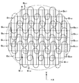
なお、ロードされたウエハW上には、図7に示されるように、被露光領域(区画領域)としての複数のショット領域Si,jがマトリクス状に配列され、各ショット領域Si,jには前層の工程における露光及び現像等によりそれぞれチップパターンが形成されるとともに、ウエハアライメント用のファインアライメントマークが付設されているものとする。
【0103】
次に、最小二乗法等の統計演算により、ウエハW上のショット領域の配列座標を算出するエンハンスト・グローバル・アライメント(EGA)方式によるファインアライメントを行う。ファインアライメント工程では、ファインアライメントマークの撮像にあたって、所定のファインアライメントマークをアライメント検出系ALGの撮像範囲に入れるために、ウエハステージWSTの移動が行われるが、このウエハステージWSTの移動の制御も、上記のレチクルアライメント等の場合と同様に行われる。このEGA方式によるファインアライメントについては、例えば、特開昭61−44429号公報に開示されている。
【0104】
次いで、ウエハW上の各ショット領域のステップ・アンド・スキャン方式による露光が行われる。なお、ショット領域Si,jの露光順序は、図7に示される通りであり、ショット領域S1,1から始まり、行方向(+X方向)に順次進む。そして、第1行の最後のショット領域S1,7の露光が終了すると、第2行の最初のショット領域S2,9へ進む。そして、第1行の行方向とは逆の行方向(−X方向)に順次進む。以後、行を変更する度に、前の行における進行方向とは逆の行方向へ進行しながら、最終のショット領域まで順次露光を行う。
【0105】
なお、図7における実線矢印は、各ショット領域における露光領域IAによるウエハWの走査方向を示している。すなわち、本実施形態では、露光順が進む度に、順次走査方向を逆転するいわゆる交互スキャン方式を採用しているものとする。なお、実際には、露光領域IAが固定でウエハWが移動するので、ショット領域の露光順が進むに従って、実際にはウエハWは、図7における実線(点線を含む)矢印と逆方向に移動する。
【0106】
かかる露光処理にあたって、まず、主制御系22は、上記のファインアライメント結果及びウエハ干渉計38からの位置情報(又は速度情報)に基づき、ステージ制御系20を介してウエハ駆動装置34を制御して、ウエハステージWSTを移動させ、ウエハWの第1ショット領域S1,1の露光のための走査開始位置(加速開始位置)にウエハWを移動させる。
【0107】
次に、ステージ制御系20は、主制御系22の指示に応じてレチクルRとウエハW、すなわちレチクルステージRSTとウエハステージWSTとのY軸方向の相対移動を開始する。両ステージRST,WSTがそれぞれの目標走査速度に達し、等速同期状態に達すると、照明系IOPからの照明光によってレチクルRのパターン領域が照明され始め、走査露光が開始される。上記の相対走査は、ステージ制御系20が、前述したウエハ干渉計38及びレチクル干渉計16の計測値をモニタしつつ、不図示のレチクル駆動部及びウエハ駆動装置34を制御することにより行われる。
【0108】
そして、ステージ制御系20は、レチクル駆動部及びウエハ駆動装置34を介してレチクルステージRST及びウエハステージWSTを同期制御する。その際、特に上記の走査露光時には、レチクルステージRSTのY軸方向の移動速度VRとウエハステージWSTのY軸方向の移動速度VWとが、投影光学系PLの投影倍率(1/4倍あるいは1/5倍)に応じた速度比に維持されるように同期制御を行う。
【0109】
そして、レチクルRのパターン領域の異なる領域が照明光で逐次照明され、パターン領域全面に対する照明が完了することにより、ウエハW上の第1ショット領域S1,1の走査露光が終了する。これにより、レチクルRのパターンが投影光学系PLを介して第1ショット領域S1,1に縮小転写される。なお、走査露光の終了後には、照明光によるレチクルRのパターン領域の照射を止める。
【0110】
以上のような走査露光における同期移動の際には、ウエハステージWST(ひいてはウエハW)の移動は、ウエハ駆動装置34の第1、第2のY軸モータ装置YMA、YMBによるY軸可動子48A、48Bの駆動によって行われる。
【0111】
以上のようにして、第1ショット領域S1,1の走査露光が終了すると、主制御系22からの指示に基づき、ステージ制御系20がウエハ駆動装置34を制御してウエハステージWSTを、例えば図7に点線で示されるようなU字状の経路(あるいはコ字状若しくはV字状の経路)に従って、ウエハWを次のショット領域(ここでは、第2ショットS1,2)の走査露光の開始位置まで移動するショット領域間のステッピング動作を行う。このステッピング動作が終了した時点では、ウエハW(ウエハステージWST)の加速動作は終了しており、ウエハWはY軸方向に関してのみ速度を有する。なお、ショット領域間のステッピング動作については、更に後述する。
【0112】
そして、ウエハW、レチクルRの移動方向が反対であることを除いて、第1ショット領域S1,1の場合と同様にして、第2ショット領域S1,2の走査露光を行う。
【0113】
以後、上記のステップ動作と走査露光動作とを繰り返して、第1行のショット領域の走査露光を順次実行する。
【0114】
そして、第1行の最後のショット領域S1,7の走査露光を終了すると、主制御系22からの指示に基づき、ステージ制御系20がウエハ駆動装置34を制御してウエハステージWSTを移動し、第2行の最初のショット領域S2,9の露光のための走査開始位置(加速開始位置)まで移動する、行間の移動動作を行う。
【0115】
引き続き、第2行においても、ショット領域の露光順序が−X方向に進行することを除いて、第1行の場合と同様にして、各ショット領域の走査露光が実行される。以後、第1行及び第2行の場合と同様にして、最終行(第7行)までの各ショット領域の走査露光が実行される。
【0116】
以上のようにして、ウエハW上の最終ショット領域S8,1に対する走査露光が完了すると、ウエハWが不図示のアンローダによって、ウエハステージWSTからアンロードされる。かかるウエハWのアンロードにあたっては、アンロード位置までウエハステージWSTが移動する。こうして、1枚のウエハWに関する一連の露光処理が終了する。なお、本実施形態では、ステップ・アンド・スキャン方式によるウエハの露光動作時に、各ショット領域の走査開始位置でウエハステージWSTを停止させることなく移動している。
【0117】
上記の露光処理中の各動作に伴い、ウエハステージWSTのY軸方向への駆動にあたっては、主制御系22からの指示に応じ、ステージ制御系20により、第1及び第2Y軸モータ装置YMA,YMBによるY軸可動子48A,48Bに与えられる駆動力が、互いに同一の大きさ及び同一の方向となるように、電流制御がなされる。この場合、第1及び第2Y軸モータ装置YMA,YMBのY軸可動子48A,48Bが、前述のように、X軸方向及びZ軸方向について非接触で拘束されているので、第1及び第2Y軸モータ装置YMA,YMBによるY軸可動子48A,48Bの駆動が安定して行われる。また、この場合、第1及び第2Y軸モータ装置YMA,YMBによるY軸可動子48A,48Bの駆動の結果、Y軸固定子42A,42BにはY軸可動子48A,48Bの駆動方向とは反対方向の反力が発生するが、Y軸固定子42A,42Bは、X軸方向及びZ軸方向に非接触で拘束されているので、かかる反力の作用により、Y軸固定子42A,42Bは、運動量保存則にほぼ従って自由運動を行い、Y軸可動子48A,48Bの駆動方向とは逆のY軸方向に移動する。この結果、Y軸固定子42A,42Bに作用する反力はほぼ完全に吸収される。従って、Y軸可動子48A,48B、すなわちウエハステージWSTのY軸方向の駆動による反力に起因する振動の発生がほぼ完全に防止される。
【0118】
また、ウエハステージWSTのX軸方向への駆動にあたっては、主制御系22からの指示に応じ、ステージ制御系20によりX軸モータXMによるX軸可動子112に与えられる駆動力が、所望の大きさ方向となるように、電流制御がなされる。この場合、X軸モータ装置XMによるX軸可動子112の駆動の結果、X軸固定子110にはX軸可動子112の駆動方向とは反対方向の反力が発生する。この場合、X軸固定子110は、Y軸方向及びZ軸方向に非接触で拘束されているので、かかる反力の作用により、X軸固定子110は、運動量保存則にほぼ従って自由運動を行い、X軸可動子112の駆動方向とは逆のX軸方向に移動する。この結果、X軸固定子110に作用する反力はほぼ完全に吸収される。従って、X軸可動子112の駆動の反力に起因する振動の発生がほぼ完全に防止される。
【0119】
ところで、上述した一連の動作に際し、例えばウエハステージWSTに対するウエハのロード、あるいはアンロードの際などには、ウエハのロード位置とウエハアライメントの開始位置(アライメント検出系ALGによるウエハのマーク又は基準マークの検出位置)との間、あるいはウエハのアンロード位置と露光終了位置との間で、ウエハステージWSTを大きなストロークで少なくともY軸方向に移動させる必要がある。このような場合に、前述したY軸固定子42A、42Bの運動量保存則に従った運動を無条件に許容すると、ウエハステージWSTとX軸固定子110とY軸可動子48A,48Bとの合計の質量と、Y軸固定子42A、42Bの質量との比、及びウエハステージWSTのストロークによって一義的に定まる大きな距離のY軸固定子42A、42Bの移動ストロークを用意しなければならない。
【0120】
そこで、本実施形態では、以下に説明するような、Y軸トリムモータ106A、108A及びY軸トリムモータ106B、108Bの制御を行うことで、上記のY軸固定子42A、42Bの移動ストロークを極力短くしている。
【0121】
図8(A)には、一例として、ウエハステージWSTのY軸方向に関する長ストローク移動時における第1及び第2Y軸モータ装置YMA,YMBの可動子であるY軸可動子48A、48Bの速度変化曲線Vy(t)及び加速度変化曲線Ay(t)が示されている。また、図8(B)には、図8(A)に対応する主制御系22によるY軸トリムモータ106A、108A及びY軸トリムモータ106B、108Bの駆動によるY軸固定子42A、42Bの加速度変化曲線CAy(t)の一例などが示されている。
【0122】
図8(A)に示されるように、主制御系22の指示に基づき、ステージ制御系20により、Y軸可動子48A、48Bに加速度変化曲線Ay(t)で示されるような加速度が与えられると、Y軸可動子48A、48Bは、速度変化曲線Vy(t)に沿って移動する。このときの移動距離は、速度変化曲線Vy(t)と横軸とで囲まれた領域の面積である。このようなY軸可動子48A、48Bの駆動による反力がY軸固定子42A、42Bに作用した場合に、前述したY軸固定子42A、42Bの運動量保存則に従った運動を無条件に許容すると、Y軸固定子42A、42Bには、図8(B)中の曲線Ry(t)で示されるような加速度が生じ、この加速度に従ってY軸固定子42A、42BがY軸可動子48A、48Bと逆向きに移動する。
【0123】
しかるに、主制御系22では、指令値Ay(t)に基づいて、所定の演算を行うことにより、曲線Ry(t)を事前に容易に求めることができる。そこで、主制御系22では、この曲線Ry(t)を算出した後、曲線Ry(t)で示されるような加速度を相殺するような加速度変化曲線CRy(t)を算出し、この加速度変化曲線CRy(t)に基づいて、Y軸トリムモータ106A、108A及びY軸トリムモータ106B、108Bを駆動するようになっている。これにより、Y軸固定子42A、42Bの運動量保存則に従った運動を完全に相殺して、Y軸固定子42A、42BをウエハステージWSTのY軸方向に関する長ストローク移動開始前の初期位置に停止させたままの状態とすることができる。
【0124】
但し、Y軸トリムモータ106A、108A及びY軸トリムモータ106B、108Bの発生可能な推力があまり大きくない場合には、一例として図8(B)中に示される加速度変化曲線CAy(t)に基づいて、Y軸トリムモータ106A、108A及びY軸トリムモータ106B、108Bを駆動することとすれば良い。この加速度変化曲線CAy(t)に基づいてY軸トリムモータ106A、108A及びY軸トリムモータ106B、108Bを駆動した場合におけるY軸固定子42A、42Bの速度変化曲線CVy(t)が図8(B)中に実線にて示されている。
【0125】
加速度変化曲線CRy(t)に基づく場合は勿論、加速度変化曲線CAy(t)に基づいてY軸トリムモータ106A、108A及びY軸トリムモータ106B、108Bを駆動する場合にも、特に不都合はない。これは、運動量保存則に従うY軸固定子42A、42Bの運動を妨害すれば、ウエハ駆動装置34に偏荷重が発生して振動が生じるが、ウエハのロード、あるいはアンロードの際などには、振動が発生しても問題がないからである。同様の理由から、前述のEGA方式のウエハアライメント時などの露光時以外の時には、主制御系22は、上述した長ストローク移動時と同様のY軸トリムモータ106A、108A及びY軸トリムモータ106B、108Bの駆動制御を行うようにしても良い。このようにすると、Y軸固定子42A、42Bのストロークを小さく設定することができる。
【0126】
これに対し、前述したステップ・アンド・スキャン方式の露光の際には、少なくとも露光光ELがウエハWに照射される露光中には、振動は極力抑制する必要がある。
【0127】
図9には、ステップ・アンド・スキャン方式により、隣接する2ショット領域に対する露光を行う際の、第1及び第2Y軸モータ装置YMA,YMBの可動子であるY軸可動子48A、48Bの速度変化曲線Vy(t)及び加速度変化曲線Ay(t)が示されている。
【0128】
図9において、符号TAで示される期間は、あるショット領域(ショット領域Aとする)の露光開始前のY軸可動子48A、48B(ウエハステージWST及びレチクルステージRST)の+Y方向への加速時間であり、符号TEで示される期間は、ショット領域Aに対する露光時間であり、符号TDで示される期間は、ショット領域Aの露光終了後の減速時間である。なお、期間TAとTEとの間の期間は、レチクルステージRSTとウエハステージWSTとの同期整定のための時間(同期整定時間)であり、期間TEとTDとの間の期間は、同期整定時間に対応する等速時間である。
【0129】
この図9に示されるように、主制御系22の指示に基づき、ステージ制御系20により、Y軸可動子48A、48Bに加速度変化曲線Ay(t)で示されるような加速度が与えられると、Y軸可動子48A、48B(ウエハステージWST)は、速度変化曲線Vy(t)に沿って移動する。このようなY軸可動子48A、48Bの駆動による反力がY軸固定子42A、42Bに作用すると、Y軸固定子42A、42Bには、加速度変化曲線Ay(t)と逆向きの加速度が生じ、この加速度に従ってY軸固定子42A、42BがY軸可動子48A、48Bと逆向きに移動する。このときの移動は、運動量保存則に従って行われ、その結果、上記の反力がY軸固定子42A、42Bの移動により完全に吸収され、振動が発生するのが防止される。
【0130】
そこで、主制御系22では、上記のY軸固定子42A、42Bの運動量保存則に従った運動を許容することとしている。
【0131】
本実施形態の場合、図7からも明らかなように、上記のY軸固定子42A、42Bの運動量保存則に従った運動を許容しても、同一行のショット領域に対する露光が行われている間は、Y軸固定子42A、42BはY軸方向に沿って所定ストロークで往復運動するのみなので、特に問題は生じない。
【0132】
但し、加速時間TAと異なり、減速時間TDでは、振動が生じても特に不都合はない。従って、主制御系22では、この減速時間TDの間だけ、前述と同様にして、指令値Ay(t)に基づいて、所定の演算を行うことにより、その加速度の少なくとも一部を相殺するような加速度変化曲線を算出し、この加速度変化曲線に基づいて、Y軸トリムモータ106A、108A及びY軸トリムモータ106B、108Bを駆動しても良い。これにより、Y軸固定子42A、42Bのストロークを減速時間中に反力の作用によって移動する距離分、あるいはその一部の分だけ短くすることができる。
【0133】
一方、同一行のショット領域に対する露光が終了して、次の行のショット領域に対する露光を行うためのウエハの移動は、比較的大きなストロークで行われること、及びこの間に振動が生じても特に不都合は無い。かかる点に鑑み、主制御系22では、先に図8(A)、図8(B)を用いて説明したのと同様の、Y軸トリムモータ106A、108A及びY軸トリムモータ106B、108Bの駆動制御を行う。
【0134】
なお、図7に示されるような経路に沿ってウエハステージのショット領域間ステッピング動作を行う場合には、Y軸方向に関して図9の速度制御(又は加速度制御)が行われるのと並行して、X軸方向に関しては、次のような制御が行われる。すなわち、ショット領域の露光終了後であってY軸方向に関する速度が零となる前にX軸方向の加速を開始し、X軸方向の減速(ステッピング)が終了する前に次のショット領域の露光のためのY軸方向への加速を開始する。この場合、露光終了後でY軸方向の速度が零となる前にX軸方向の加速を開始するだけでも良いし、あるいはステッピング終了前にY軸方向への加速を開始するだけでも良い。なお、次ショット領域の露光のためのY軸方向への加速が終了する前にX軸方向の減速(ステッピング)を終了させることが好ましい。かかるウエハステージのショット領域間ステッピング動作に関する詳細は、例えば特開2000−106340号公報などに開示されており、公知であるから詳細説明については省略する。
【0135】
また、ここまでは、レチクルR(レチクルステージRST)とウエハW(ウエハステージWST)との同期移動方向、すなわち走査方向であるY軸方向に関するウエハステージWSTの駆動時の反力の作用によるY軸固定子42A、42Bの運動制御について説明したが、主制御系22では、上記と同様にして、ウエハステージWSTのX軸方向駆動時に生じる反力の作用によるX軸固定子110の運動量保存則に従う運動を完全に、あるいは一部相殺すべく、前述の電機子ユニット114と磁石群128A等からなる磁極ユニットとによって構成されるX軸トリムモータを制御するようになっている。従って、X軸固定子110についてもストロークを小さく設定することができる。ここで、前述の露光期間TEでは、ウエハステージWSTの速度、加速度は共に零であり、X軸モータ装置XMは、駆動力(推力)を発生していないので、前述のX軸トリムモータの制御は不要である。
【0136】
これまでの説明から明らかなように、本実施形態では、レチクル駆動部15、ウエハ駆動装置34及びステージ制御系20によって、レチクルステージRSTとウエハステージWSTとを駆動する駆動系が構成され、Y軸固定子42A,42B、X軸固定子110によってカウンタマスがそれぞれ構成されている。また、Y軸トリムモータ106A,108A,106B,108B及び前述のX軸トリムモータによってカウンタマス駆動系が構成され、主制御系22によってカウンタマス駆動系を制御する制御装置が構成されている。
【0137】
以上説明したように、本実施形態に係る露光装置100によると、主制御系22により、露光に影響を与えない範囲で、ステージ制御系20によるウエハ駆動装置34を介したウエハステージWSTの駆動状態に応じて、Y軸固定子42A,42B、X軸固定子110の運動量保存則に従った運動を少なくとも一部相殺するように、Y軸トリムモータ106A,108A,106B,108B及び前述のX軸トリムモータが制御される。これにより、ウエハステージWSTの駆動時の反力に起因するY軸固定子42A,42B、X軸固定子110の運動量保存則に従った運動の際の移動ストロークを小さく設定できるので、露光装置100のフットプリントの狭小化、あるいはY軸トリムモータ106A,108A,106B,108B及び前述のX軸トリムモータの小型化が可能となる。従って、露光装置100によると、露光精度の低下を招くことなく、装置の大型化を抑制することが可能となる。
【0138】
また、本実施形態の露光装置100によると、主制御系22は、レチクルステージRSTとウエハステージWSTとのY軸方向に関する加減速度がともに零となる両ステージRST、WSTの同期移動時、すなわち前述の整定時間、露光時間TEを除く特定の時、例えばウエハ上の任意のショット領域の露光終了後に、Y軸方向に関しレチクルステージRSTとウエハステージWSTとを同時に減速する時、あるいはウエハ交換のためのウエハステージWSTの移動時(ウエハロード、ウエハアンロードの際のウエハステージWSTの移動時)及びウエハステージWST上のウエハWとレチクルRとの位置関係の計測のためのウエハステージWSTの移動時、例えば前述のレチクルアライメント、EGA方式のウエハアライメントの際のウエハステージWSTの移動時、及び異なる行のショット領域間のウエハステージWSTの移動時などの長ストロークの移動時に、ステージ制御系20によるウエハ駆動装置34を介したウエハステージWSTの駆動状態に応じて、Y軸トリムモータ106A,108A,106B,108B及び前述のX軸トリムモータの少なくとも一方を制御する。このため、露光精度を低下させることなく、Y軸固定子42A,42B及びX軸固定子110の少なくとも一方のストロークを小さく設定することができる。
【0139】
また、本実施形態の露光装置100によると、主制御系22が、上記のウエハステージWSTの長ストローク移動時に、Y軸トリムモータ106A,108A,106B,108B及び前述のX軸トリムモータを介してY軸固定子42A,42B及びX軸固定子110を駆動し続ける場合には、これらのトリムモータの最大加速度(最大推力)を小さくすることができるので、トリムモータの小型化も可能である。
【0140】
また、本実施形態では、X軸固定子及びY軸固定子がウエハステージの反力を吸収するカウンタマスとされているので、ウエハステージとは別個にカウンタマスを用意しなくても、ウエハステージの駆動により生じる反力に起因する振動を吸収することができる。このため、露光装置全体のフットプリントの狭小化を図ることが可能となる。
【0141】
なお、上記実施形態では、ウエハに対して第2層目(セカンドレイヤ)以降の層の露光処理を行う場合について説明したが、これに限らず、ウエハの位置合わせ(サーチアライメント、ファインアライメント)が行なわれないことを除いて第2層目(セカンドレイヤ)以降の層の露光処理と同様に行なわれるウエハの第1層目(ファーストレイヤ)の露光処理についても、上記実施形態と同様の効果を得ることができる。
【0142】
《第2の実施形態》
次に、本発明の第2の実施形態を、図10(A)及び図10(B)に基づいて説明する。本第2の実施形態に係る露光装置は、装置構成などは前述した第1の実施形態と同様であり、ステップ・アンド・スキャン方式の露光の際のY軸固定子42A,42Bの運動制御のための、Y軸トリムモータ106A、108A、106B、108B等の制御動作が異なるのみである。従って、以下では、かかる相違点を中心として、説明する。なお、装置各部などの符号は、前述の第1の実施形態と同一の符号を用いるものとする。
【0143】
本第2の実施形態の露光装置においても、図7に示されるような経路に沿ってかつ前述と同様の手順でウエハW上の各ショット領域に対しステップ・アンド・スキャン方式による露光が行われる。
【0144】
図10(A)には、Y軸トリムモータ106A、108A、106B、108B等の制御を行わなかった場合における、上記の露光の際のウエハステージWSTの移動に伴う、Y軸固定子42A(又は42B)のY軸方向の位置の変化(変化曲線y=L(t))が、時間t(ショット領域に対応)を横軸として示されている。この図10(A)からわかるように、第1ショット領域の露光開始前の時点から最終ショットの露光終了時点までの間に、Y軸固定子42A(又は42B)は、同一行のショット領域に対する露光の間には、所定範囲でY軸方向に関して所定ストローク範囲で往復移動しながら、行が代わると、往復移動の中心が+Y方向に所定距離だけシフトするという、移動状況を繰り返しながら、全体として+Y方向に距離Lの定常変位が発生する。この場合、Y軸固定子42A(又は42B)のストロークとして最低でも定常変位Lと同等のストロークが必要となる。
【0145】
例えば、ウエハWの直径が300mmであり、ウエハステージWSTを含む前述の可動部の質量と、Y軸固定子42A、42Bの合計の質量との比が、1:2である場合、Y軸固定子42A、42Bには、約150mmの定常変位が発生する。
【0146】
そこで、本第2の実施形態では、主制御系22が、次のようなY軸トリムモータ106A、108A及びY軸トリムモータ106B、108Bの制御を行っている。
【0147】
すなわち、主制御系22は、ステップ・アンド・スキャン方式による複数のショット領域に対するパターンの転写動作シーケンス中に、その転写動作シーケンスに要する時間T0と、ウエハステージWSTとX軸固定子110とY軸可動子48A、48Bとを含む可動部と、Y軸固定子42A、42Bとの質量比に応じて定まる前記転写動作シーケンス中のY軸固定子42A、42Bの運動量保存則に従った運動による+Y方向の定常変位Lとに基づいて定まる−Y方向(定常変位と反対方向)の平均速度Vave=L/T0がY軸固定子42A及び42Bに与えられるように、Y軸トリムモータ106A、108A及びY軸トリムモータ106B、108Bを制御する。図10(A)には、上記の平均速度を傾きとするY軸固定子42A、42BのY軸方向の位置の変化(変化直線y=Vave・t)が併せて示されている。
【0148】
この場合、ステップ・アンド・スキャン方式による複数のショット領域に対するパターンの転写動作シーケンス中には、ウエハステージWSTの駆動に応じ、その駆動によって生じる反力の作用によってY軸固定子42A、42BがY軸方向に沿って運動量保存則にほぼ従った運動をし、Y軸方向に関して往復運動を繰り返しながら、+Y側に徐々に移動する。この際、Y軸固定子42A、42Bが運動量保存則に従って−Y方向に移動する場合にはその移動動作がY軸トリムモータ106A、108A及びY軸トリムモータ106B、108Bから加えられる力によってアシストされ、反対に+Y方向に移動する場合にはその移動動作がY軸トリムモータ106A、108A及びY軸トリムモータ106B、108Bから加えられる力によって抑制される。
【0149】
これを更に詳述すると、ウエハW上の第1行のショット領域S1,1〜S1,7を露光する間には、ウエハステージWSTは、一定範囲内でY軸方向に沿って往復移動し、これに応じてY軸固定子42A、42Bも一定範囲内でY軸方向に沿って往復移動する。これに対し、第1行目の最後のショット領域S1,7の露光終了後第2行目の最初のショット領域S2,9の露光開始前には、ウエハステージWSTが−Y方向にそれまでと比べて大きく移動し、これに応じてY軸固定子42A、42Bが+Y方向に移動しようとするが、この移動動作がY軸トリムモータ106A、108A及びY軸トリムモータ106B、108Bから加えられる力によって抑制される。
【0150】
同様に、ウエハW上の第2行のショット領域S2,9〜S2,1を露光する間には、ウエハステージWSTは、一定範囲内でY軸方向に沿って往復移動し、これに応じてY軸固定子42A、42Bも一定範囲内でY軸方向に沿って往復移動する。これに対し、第2行目の最後のショット領域S2,1の露光終了後、第3行目の最初のショット領域S3,1の露光開始前には、ウエハステージWSTが−Y方向にそれまでと比べて大きく移動し、これに応じてY軸固定子42A、42Bが+Y方向に移動しようとするが、この移動動作がY軸トリムモータ106A、108A及びY軸トリムモータ106B、108Bから加えられる力によって抑制される。
【0151】
以後同様に、異なる行間のウエハステージWSTの移動に際して、Y軸固定子42A、42Bの+Y方向の移動が、Y軸トリムモータ106A、108A及びY軸トリムモータ106B、108Bから加えられる力によって抑制される。
【0152】
図10(B)には、上述の如くしてY軸固定子42A、42Bの+Y方向の移動が抑制された結果におけるY軸固定子42A(又は42B)のY軸方向の位置の変化y=ΔL=L(t)−Vave・tが、時間t(ショット領域に対応)を横軸として示されている。
【0153】
この図10(B)の曲線y=ΔLと前述の図10(A)の曲線y=L(t)とを比較すると明らかなように、異なる行間のウエハステージWSTの移動に際して生じる、Y軸固定子42A、42Bの+Y方向の移動を、Y軸トリムモータ106A、108A及びY軸トリムモータ106B、108Bから加えられる力によって抑制した結果、本実施形態では、露光中にトリムモータの制御を行わない従来技術に比べて、ステップ・アンド・スキャン方式による複数のショット領域に対するパターンの転写動作シーケンス中に、Y軸固定子42A、42Bに生じる+Y方向の定常変位を格段に抑制することができ、その分Y軸固定子42A、42BのY軸方向の移動ストロークを小さく設定することが可能となることがわかる。
【0154】
この場合において、ステップ・アンド・スキャン方式による複数のショット領域に対するパターンの転写動作シーケンスに要する時間は、通常数10秒という長い時間であるため、上記の平均速度Vaveは、小さく、その平均速度Vaveを与えるY軸トリムモータ106A、108A及びY軸トリムモータ106B、108Bの駆動力が、露光中のY軸固定子42A、42Bの運動量保存則に従った運動に与える影響は僅かであり、露光精度に影響を与えるものではない。
【0155】
従って、本第2の実施形態の露光装置によると、前述の第1の実施形態と同様に、レチクルパターンとウエハW上の複数のショット領域との重ね合わせ精度の低下を招くことがないとともに、露光装置のフットプリントの狭小化、あるいはY軸固定子42A、42Bの小型化が可能となり、いずれにしても露光精度の低下を招くことなく、装置の大型化を抑制することが可能となる。
【0156】
なお、上記の説明では、説明の簡略化のため特に触れなかったが、ウエハ駆動装置が、ウエハステージWSTをY軸方向に駆動する左右一組のモータとしてのY軸モータ装置YMA、YMBを含み、かつカウンタマスとしてのY軸固定子42A、42Bは、各Y軸モータ装置YMA、YMBに個別に対応して設けられている。また、ウエハステージWSTのX軸方向の位置に応じてウエハステージWSTを含む前述の可動部の重心位置が異なるので、ウエハステージWSTをY軸方向に正確に駆動する際には、主制御系22は、ウエハステージWSTのX軸方向の位置に応じてY軸モータ装置YMA、YMBにそれぞれに対する推力配分を考慮して、前記転写動作シーケンス中、前記Y軸固定子42A、42Bを個別に制御することとしても良い。かかる場合には、露光時間中のY軸固定子42A、42Bそれぞれの変位を時間軸を横軸とする直交座標系上でプロットし、これを最小二乗近似した速度に応じた速度をY軸固定子42A、42Bに与えることとすることが望ましい。
【0157】
なお、上記第2の実施形態では、Y軸方向に関する定常変位Lを軽減すべく定常変位と反対方向の平均速度Vave=L/T0がY軸固定子42A及び42Bに与えられるように、Y軸トリムモータ106A、108A及びY軸トリムモータ106B、108Bを制御するものとしたが、ショットマップによっては、レチクルパターンが転写される最初のショット領域と最後のショット領域とのウエハ上におけるX軸方向(非走査方向)の位置が異なる。このような場合には、その非走査方向に関しても転写動作シーケンスの開始位置と終了位置とでX軸固定子110にX軸方向の定常変位が生じる。このような場合、主制御系22では、転写動作シーケンス中に、前記時間T0と、可動部としてのウエハステージWSTとX軸固定子110との質量比とに応じて定まる転写動作シーケンス中のX軸固定子110の運動量保存則に従った運動による定常変位(Dとする)を考慮した定常変位と反対向きのX軸方向に関する平均速度(=D/T0)がX軸固定子110に与えられるように、前述のX軸トリムモータを制御することとすることができる。これにより、Y軸固定子42A、41Bの移動ストロークに加え、X軸固定子110の移動ストロークをも小さく設定することができる。
【0158】
なお、上記各実施形態では、ウエハステージWSTの反力を吸収する機構として、ウエハステージWSTを移動させる各モータ装置の固定子を用いる構成としたが、これに限らず、各モータ装置とは別にカウンタマスを設けることも可能である。
【0159】
また、上記各実施形態では、ウエハステージWSTを1つだけ備える構成としたが、これに限らず、互いに独立して2次元移動が可能な2つのウエハステージを備える構成とすることができる。この場合、二つのアライメント検出系を持つタイプ(すなわち、一方のウエハステージが一方のアライメント検出系と投影光学系PLとの間で移動し、他方のウエハステージが他方のアライメント検出系と投影光学系PLとの間で移動するタイプ)のダブルウエハステージ方式のスキャニング・ステッパにも、一つのアライメント検出系のみを持つタイプ(すなわち、2つのウエハステージが投影光学系とアライメント検出系との間で交互に入れ替わるタイプ)のダブルウエハステージ方式のスキャニング・ステッパにも本発明は好適に適用することができる。また、ダブルウエハステージ方式のスキャニング・ステッパ(露光装置)では、2つのウエハステージにそれぞれ対応して別々のカウンタマスを設けても良いし、あるいは2つのウエハステージで共通のカウンタマスを設けるだけでも良い。特に後者では、例えば国際公開WO01/47001号パンフレットに開示されているように、2つのウエハステージが載置される可動定盤をカウンタマスとして用いても良い。
【0160】
また、上記各実施形態の露光装置は床面(又はベース)F上で防振ユニットに支持されるベースにウエハステージWSTが載置されるものとしたが、例えば上記ウエハステージWSTが載置されるベースを鏡筒定盤30に吊り下げる構造としても良く、要は本発明が適用される露光装置のボディ構造は上記各実施形態に限られるものではなく任意で構わない。
【0161】
勿論、本発明は、半導体素子の製造に用いられる露光装置だけでなく、液晶表示素子、プラズマディスプレイなどを含むディスプレイの製造に用いられる、デバイスパターンをガラスプレート上に転写する露光装置、薄膜磁気へッドの製造に用いられる、デバイスパターンをセラミックウエハ上に転写する露光装置、及び撮像素子(CCDなど)、有機EL、マイクロマシン、DNAチップなどの製造に用いられる露光装置などにも適用することができる。
【0162】
また、半導体素子などのマイクロデバイスだけでなく、光露光装置、EUV(Extreme Ultraviolet)露光装置、X線露光装置、及び電子線露光装置などで使用されるレチクル又はマスクを製造するために、ガラス基板又はシリコンウエハなどに回路パターンを転写する露光装置にも本発明を適用できる。ここで、DUV(遠紫外)光やVUV(真空紫外)光などを用いる露光装置では一般的に透過型レチクルが用いられ、レチクル基板としては石英ガラス、フッ素がドープされた石英ガラス、蛍石、フッ化マグネシウム、又は水晶などが用いられる。また、プロキシミティ方式のX線露光装置、又は電子線露光装置などでは透過型マスク(ステンシルマスク、メンブレンマスク)が用いられ、EUV露光装置では反射型マスクが用いられ、マスク基板としてはシリコンウエハなどが用いられる。
【0163】
また、本発明に係る露光装置では、投影光学系に限らず、X線光学系、電子光学系等の荷電粒子線光学系を用いることもできる。例えば、電子光学系を用いる場合には、光学系は電子レンズ及び偏向器を含んで構成することができ、電子銃として、熱電子放射型のランタンへキサボライト(LaB6)、タンタル(Ta)を用いることができる。なお、電子線が通過する光路は真空状態にすることはいうまでもない。また、本発明に係る露光装置では、露光光として、前述した遠紫外域、真空紫外域の光に限らず、波長5〜30nm程度の軟X線領域のEUV光を用いても良い。
【0164】
また、例えば真空紫外光としては、ArFエキシマレーザ光やF2レーザ光などが用いられるが、これに限らず、DFB半導体レーザ又はファイバーレーザから発振される赤外域、又は可視域の単一波長レーザ光を、例えばエルビウム(又はエルビウムとイッテルビウムの両方)がドープされたファイバーアンプで増幅し、非線形光学結晶を用いて紫外光に波長変換した高調波を用いても良い。
【0165】
また、上記各実施形態では、投影光学系として縮小系を用いる場合について説明したが、投影光学系は等倍系および拡大系のいずれでも良い。
【0166】
なお、複数のレンズ等から構成される照明ユニット、投影光学系などを露光装置本体に組み込み、光学調整をする。そして、上記のX軸固定子、X軸可動子、Y軸固定子、ウエハステージ、レチクルステージ、並びにその他の様々な部品を機械的及び電気的に組み合わせて調整し、更に総合調整(電気調整、動作確認等)をすることにより、上記実施形態の露光装置100等の本発明に係る露光装置を製造することができる。なお、露光装置の製造は温度およびクリーン度等が管理されたクリーンルームで行うことが望ましい。
【0167】
【発明の効果】
以上説明したように、本発明の露光装置によれば、精度良く露光を行えるとともに、装置の大型化を抑制することができるという従来にない優れた効果がある。
【図面の簡単な説明】
【図1】本発明の第1の実施形態に係る露光装置の構成を概略的に示す図である。
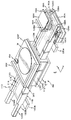
【図2】図1のウエハステージ装置を示す斜視図である。
【図3】図2のウエハステージ及びその駆動装置を一部破断して示す図である。
【図4】図4(A)は、図2のD−D線断面図であり、図4(B)は、図2のY軸固定子42B及び枠体44Bを+X方向から見た図である。
【図5】図3からX軸固定子を取り去り、X軸可動子の一部を破断して示す図である。
【図6】X軸モータ装置XM及びY軸可動子48A,48Bを高さ方向中央やや上方の位置でXY面に平行な面に沿って断面し、その一部を省略して示す図である。
【図7】ウエハ上の複数のショット領域に対する照明光の移動軌跡の一例を示す図である。
【図8】図8(A)は、ウエハステージWSTのY軸方向に関する長ストローク移動時におけるY軸可動子48A、48Bの速度変化曲線Vy(t)及び加速度変化曲線Ay(t)を示す図、図8(B)は、図8(A)に対応するステージ制御系によるリニアモータ106A、108A,106B,108Bの駆動によるY軸固定子42A、42Bの加速度変化曲線CAy(t)の一例などを示す図である。
【図9】図9は、隣接する2ショット領域に対する露光を行う際の、Y軸可動子48A、48Bの速度変化曲線Vy(t)及び加速度変化曲線Ay(t)を示す図である。
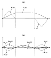
【図10】図10(A)は、比較例として、Y軸トリムモータの制御を行わなかった場合における、露光の際のウエハステージの移動に伴う、Y軸固定子のY軸方向の位置の変化を横軸をショット領域として示す図、図10(B)は、第2の実施形態の露光装置における、露光動作の際のウエハステージWSTの移動に伴う、Y軸固定子のY軸方向の位置の変化を、ショット領域を横軸として示す図である。
【符号の説明】
R…レチクル(マスク)、W…ウエハ(感光物体)、RST…レチクルステージ(マスクステージ)、WST…ウエハステージ(物体ステージ)、15…レチクル駆動部(駆動系の一部)、20…ステージ制御系(駆動系の一部)、22…主制御系(制御装置)、34…ウエハ駆動装置(駆動系の一部)、42A,42B…Y軸固定子(カウンタマス)、106A,108A,106B,108B…Y軸トリムモータ(カウンタマス駆動系の一部)、100…露光装置、110…X軸固定子(カウンタマス)。[0001]
TECHNICAL FIELD OF THE INVENTION
The present invention relates to an exposure apparatus, and more particularly, to an exposure apparatus used in a lithography process for manufacturing an electronic device such as a semiconductor device and a liquid crystal display device.
[0002]
[Prior art]
2. Description of the Related Art Conventionally, various exposure apparatuses have been used in a lithography process in manufacturing a semiconductor element, a liquid crystal display element, and the like. In recent years, a step-and-repeat type reduction projection exposure apparatus (a so-called stepper), a step-and-scan type scanning projection exposure apparatus (a so-called scanning stepper), and the like have been relatively frequently used.
[0003]
In this type of exposure apparatus, it is necessary to transfer a reticle pattern as a mask to a plurality of shot areas on a wafer. For this reason, the wafer stage is driven in the XY two-dimensional directions by a driving device including, for example, a linear motor. The reaction force generated by driving the wafer stage is, for example, a reference (for example, a floor surface or an The processing is performed by mechanically escaping to the floor (ground) using a frame member provided on a reference base plate or the like (for example, see Patent Document 1).
[0004]
Also, for example, in the case of a scanning stepper, not only the wafer stage but also the reticle stage needs to be driven by a linear motor or the like in a predetermined scanning direction, but in order to absorb a reaction force generated by driving the reticle stage. Employs a counter mass mechanism for one axis in the scanning direction mainly using the law of conservation of momentum (for example, see Patent Document 2). There is also known a scanning exposure apparatus having a wafer stage provided with a counter stage (counter mass) and a correction device (trim motor or the like) for correcting the position of the counter stage (for example, see Patent Document 3). In addition, there is a type in which a reaction force generated by movement of a reticle stage is mechanically released to a reference, that is, a floor (ground) using a frame member (for example, see Patent Document 4).
[0005]
[Patent Document 1]
JP-A-8-166475
[Patent Document 2]
JP-A-8-63231
[Patent Document 3]
JP-A-2002-208562
[Patent Document 4]
JP-A-8-330224
[0006]
[Problems to be solved by the invention]
In a conventional projection exposure apparatus, the reaction force of the stage released to the reference is attenuated by a vibration isolator such as a vibration isolation table (anti-vibration table), and the vibration of the projection optical system (projection lens) caused by the reaction force is thereby reduced. And the vibration of the stage due to the wraparound through the reference was reduced. However, even though the reaction force of the stage escaped to the reference is attenuated, the level required in the current micromachining will give a considerable amount of vibration to the projection optical system and the stage. . For this reason, in a scanning stepper that performs exposure while scanning a stage (and, consequently, a wafer or a reticle), a vibration caused by the reaction force causes a reduction in exposure accuracy.
[0007]
On the other hand, when the reaction force is absorbed by using the counter mass mechanism, the transmission of the reaction force can be almost completely prevented. However, in the conventional counter mass mechanism, the direction opposite to the stage driving direction is used. A counter mass that moves by a distance proportional to the driving distance of the stage has been used. For this reason, a stroke corresponding to (proportional to) the entire stroke of the stage must be prepared for the counter mass, which tends to increase the size of the exposure apparatus. In an exposure apparatus including a counter stage and a correction device for correcting the position of the counter stage, such as the exposure device described in Patent Document 3, the position of the counter stage can be corrected by the correction device. The stroke of the counter stage can be shortened as compared with a case where the correction device is not provided. Further, in the scanning exposure apparatus described in Patent Document 3, the main purpose is to prevent the occurrence of vibration, and in any operation, the movement of the counter stage according to the law of conservation of momentum is allowed to move the counter stage. To achieve complete absorption of the reaction force. In the scanning exposure apparatus described in Patent Document 3, the position of the counter stage is corrected solely for the purpose of securing the stroke of the counter stage at the time of the next operation. However, for example, when the exposure to the wafer is completed and the wafer stage moves to the wafer exchange position, if the movement according to the momentum conservation rule of the counter stage is permitted, the movement distance, that is, the position of the wafer from the position at the end of the exposure is reduced. It was necessary to secure a large stroke of the counter stage according to the distance to the replacement position. In this case, it is difficult to effectively suppress an increase in the size of the device.
[0008]
The present invention has been made under such circumstances, and an object of the present invention is to provide an exposure apparatus that can suppress an increase in the size of an apparatus without causing a decrease in exposure accuracy.
[0009]
[Means for Solving the Problems]
In general, in a scanning exposure apparatus, both an operation in which vibration is hardly allowed and an operation in which some vibration is allowed are performed. The present invention focuses on this point and employs the following configuration.
[0010]
According to the first aspect of the invention, the mask (R) and the photosensitive object (W) are synchronously moved in the first axial direction, and the pattern formed on the mask is sequentially transferred to a plurality of divided areas on the photosensitive object. A mask stage (RST) on which the mask is mounted; an object stage (WST) on which the photosensitive object is mounted; and a driving system (15, 20, 34); at least one counter mass (42A, 42B, 110) that moves in accordance with the law of conservation of momentum by the action of a reaction force generated when the object stage is driven by the drive system; and a counter mass that drives the counter mass. A driving system (106A, 106B, 108A, 108B, etc.) so as to at least partially offset the motion of the counter mass according to the momentum conservation law. Is an exposure apparatus comprising a; control unit (22) for controlling the counter mass drive system in accordance with the driving state of the object stage by said drive system.
[0011]
According to this, the control device controls the counter mass driving system according to the driving state of the object stage by the driving system so as to at least partially cancel the motion of the counter mass according to the law of conservation of momentum. In this case, the control device controls the countermass drive system in a range that does not affect the exposure and in accordance with the drive state of the object stage by the drive system, thereby controlling the movement of the countermass in accordance with the momentum conservation law. Part or all can be offset. Accordingly, the movement stroke of the counter mass at the time of movement in accordance with the law of conservation of momentum caused by the reaction force at the time of driving the object stage can be set small, so that the footprint of the exposure apparatus can be narrowed or the counter mass can be downsized. In any case, it is possible to suppress an increase in the size of the apparatus without lowering the exposure accuracy.
[0012]
In this case, as in the exposure apparatus according to claim 2, the control device is configured to control the mask stage and the object stage in which the acceleration / deceleration of the mask stage and the object stage in the first axis direction are both zero. At a specific time other than the synchronous movement, the control of the counter mass drive system according to the drive state of the object stage by the drive system can be performed.
[0013]
In this case, as in the exposure apparatus according to claim 3, the control device controls the movement of the counter mass in the first axial direction and the counter in accordance with the momentum conservation law via the counter mass drive system. At least one of the movements of the mass in the second axis direction orthogonal to the first axis direction according to the law of conservation of momentum can be at least partially offset.
[0014]
In each of the exposure apparatuses according to the second and third aspects, as in the exposure apparatus according to the fourth aspect, at the specific time, after exposing an arbitrary partitioned area on the photosensitive object, the first axial direction The method may include a case where the mask stage and the object stage are simultaneously decelerated.
[0015]
In each of the exposure apparatuses according to the second and third aspects, as in the exposure apparatus according to the fifth aspect, at the specific time, when the object stage is moved to exchange a photosensitive object, and when the object stage is moved. At least one of the movements of the object stage for measuring the positional relationship between the photosensitive object and the mask.
[0016]
In this case, as in the exposure apparatus according to claim 6, the control device is configured to control the positional relationship between the photosensitive object on the object stage and the mask when the object stage is moved for exchanging the photosensitive object. In at least one of the movements of the object stage for the measurement, the counter mass may be continuously driven via the counter mass drive system during the movement of the object stage.
[0017]
In each of the exposure apparatuses according to the second and third aspects, as in the exposure apparatus according to the seventh aspect, at the specific time, the movement of the object stage during exposure of two divided areas on the photosensitive object. It can include at least a portion of the time.
[0018]
According to an eighth aspect of the present invention, the mask (R) and the photosensitive object (W) are synchronously moved in the first axial direction, and the pattern formed on the mask is stepped into a plurality of divided areas on the photosensitive object. An exposure apparatus for sequentially transferring data by an AND scan method, comprising: a mask stage (RST) on which the mask is mounted; an object stage (WST) on which the photosensitive object is mounted; A drive system (15, 20, 34) for driving; at least one counter mass (42A, 42B, 110) that moves in accordance with the law of conservation of momentum by the action of a reaction force generated when the object stage is driven by the drive system; A counter mass driving system (106A, 108A, 106B, 108B) for driving a counter mass; and the counter by the step-and-scan method. During the transfer operation sequence of the pattern to the partitioned area, the time required for the transfer operation sequence and the mass of the counter mass in the transfer operation sequence determined according to the mass ratio between the movable part including the object stage and the counter mass A control device (22) that controls the counter mass drive system such that at least an average speed in the first axis direction is given to the counter mass in consideration of a steady displacement due to motion according to the law of conservation of momentum. Exposure apparatus provided.
[0019]
According to this, during the pattern transfer operation sequence for the plurality of partitioned areas by the step-and-scan method, the control device determines the time required for the transfer operation sequence, the movable unit including the object stage, and the counter mass. The average speed in at least the first axial direction (synchronous movement direction) taking into account a steady displacement due to movement of the counter mass in accordance with the law of conservation of momentum during the transfer operation sequence determined according to the mass ratio of The counter mass drive system is controlled so as to be given to the mass. For this reason, during the pattern transfer operation sequence to a plurality of partitioned areas by the step-and-scan method, the counter mass almost follows the law of conservation of momentum due to the reaction force generated by the drive in response to the drive of the object stage. When the movement is performed, for example, when the exposure is performed by a completely alternate scan, the counter mass gradually moves from one side to the other side while repeating reciprocating movement in the first axis direction. However, the time required for the transfer operation sequence and the steady displacement due to the movement according to the momentum conservation law of the counter mass in the transfer operation sequence determined according to the mass ratio between the movable part including the object stage and the counter mass are considered. Since the counter mass drive system is controlled so that the average speed in the first axis direction is given to the counter mass, the steady displacement of the counter mass is suppressed by the force generated by the counter mass drive system. Therefore, the movement stroke of the counter mass can be set small in the first axis direction. Also, the time required for the pattern transfer operation sequence to a plurality of partitioned areas by the step-and-scan method is usually a long time of several tens of seconds. The average speed divided is small, and the driving force of the counter mass drive system that gives the average speed does not hinder the movement of the counter mass according to the law of conservation of momentum during exposure.
[0020]
Therefore, the overlay accuracy of the mask pattern and the photosensitive object is not reduced, and the footprint of the exposure apparatus can be narrowed, or the countermass can be downsized. In any case, the exposure accuracy is reduced. Without increasing the size of the apparatus, it is possible to suppress the size of the apparatus.
[0021]
In this case, as in the exposure apparatus according to the ninth aspect, the control device is configured such that a first partitioned area to which the pattern is transferred and a last partitioned area are orthogonal to the first axis direction on the photosensitive object. When the position in the second axis direction is different, during the transfer operation sequence, the time required for the transfer operation sequence and the mass ratio between the movable portion and the counter mass determined in the transfer operation sequence The counter mass drive system may be controlled such that an average speed in the second axis direction is given to the counter mass in consideration of a steady displacement due to the motion of the counter mass according to the law of conservation of momentum. it can.
[0022]
In each of the exposure apparatuses according to claims 8 and 9, as in the exposure apparatus according to
[0023]
BEST MODE FOR CARRYING OUT THE INVENTION
<< 1st Embodiment >>
Hereinafter, a first embodiment of the present invention will be described with reference to FIGS. FIG. 1 shows a schematic configuration of an
[0024]
The
[0025]
The illumination system IOP includes, for example, a light source unit, an illuminance uniforming optical system (including an optical integrator), a beam splitter, and a light source as disclosed in Japanese Patent Application Laid-Open Nos. 9-320956 and 4-196513. The reticle R is composed of an optical lens system, a reticle blind, an imaging lens system, and the like (all not shown), and is provided with exposure illumination light (hereinafter simply referred to as “exposure light”) EL having a substantially uniform illuminance distribution. Is illuminated with uniform illuminance in the rectangular (or arc-shaped) illumination area IAR. Here, as the exposure light EL, for example, ultraviolet bright lines (g-line, i-line) from an ultra-high pressure mercury lamp, KrF excimer laser light (wavelength 248 nm), ArF excimer laser light (wavelength 193 nm), F 2 Light in the deep ultraviolet region such as laser light (wavelength 157 nm) or in the vacuum ultraviolet region is used.
[0026]
The reticle stage RST is mounted on a
[0027]
On reticle stage RST, reticle R is fixed, for example, by vacuum suction. The reticle stage RST can be finely driven two-dimensionally in a plane perpendicular to the Z-axis (in the X-axis direction, in the Y-axis direction perpendicular to the X-axis direction, and in the rotation direction (θz direction) around the Z-axis perpendicular to the XY plane). Is configured.
[0028]
The reticle stage RST is moved on a
[0029]
A moving
[0030]
Position information (or speed information) of the reticle stage RST from the
[0031]
The
[0032]
The
[0033]
The
[0034]
The projection optical system PL is inserted from above into an opening (not shown) formed at the center of the
[0035]
Further, an off-axis type alignment detection system ALG is provided near the projection optical system PL. As the alignment detection system ALG, for example, a target band is irradiated with a broadband detection light beam that does not expose the resist on the wafer, and an image of the target mark formed on the light receiving surface by reflected light from the target mark is not shown. An FIA (Filed Image Alignment) -based alignment sensor of an image processing system that captures an image of the target using an image sensor (CCD) or the like and outputs an image signal of the image is used. Based on the output of the alignment detection system ALG, it is possible to measure the position of a reference mark on a reference mark plate and an alignment mark on the wafer in the X and Y two-dimensional directions, which will be described later. In addition to the FIA system, a target mark is irradiated with coherent detection light to detect scattered light or diffracted light generated from the target mark, or two diffracted lights (for example, the same order) generated from the target mark. Of course, it is possible to use an alignment sensor for detecting by causing interference with each other alone or in an appropriate combination.
[0036]
Information from the alignment detection system ALG is A / D-converted by an alignment control device (not shown), and a digitized waveform signal is arithmetically processed to detect a mark position. This result is sent to the
[0037]
The
[0038]
The wafer stage WST includes an
[0039]
A wafer W is fixed on the upper surface of the wafer table TB via a wafer holder (not shown) by electrostatic suction or vacuum suction. A reference on which various reference marks including a reference mark for baseline measurement for measuring the distance from the detection center of the alignment detection system ALG to the optical axis of the projection optical system PL is formed on the wafer table TB. The mark plate FM is fixed.
[0040]
On the upper surface of the wafer table TB, as shown in FIG. 2, an X
[0041]
An X-axis interferometer and a Y-axis interferometer (both not shown) are provided at positions facing the reflecting surfaces of these
[0042]
Next, the
[0043]
As shown in FIG. 2, the
[0044]
Here, the first Y-axis motor device YMA (more specifically, a Y-
[0045]
The first Y-axis motor device YMA takes out a part of the wafer stage WST and its driving device in FIGS. 2 and 2 and cuts out a part thereof, as shown in FIG. And a Y-
[0046]
The Y-
[0047]
As shown in FIG. 3, the
[0048]
The
[0049]
As shown in FIG. 3, the holding
[0050]
As shown in FIG. 3, the holding
[0051]
The Y-
[0052]
As shown in FIGS. 2 and 3, the Y-
[0053]
A bearing device similar to a bearing device 92B (see FIG. 3) provided on a
[0054]
A
[0055]
An
[0056]
In the first Y-axis motor device YMA configured as described above, the current flowing through the armature coils forming the
[0057]
The magnitude and direction of the driving force acting on the Y-
[0058]
Further, a coolant for cooling the armature coils is supplied to the
[0059]
As shown in FIG. 2, the second Y-axis motor device YMB has the same configuration as the above-described first Y-axis motor device YMA, though it is rotationally symmetric. That is, the second Y-axis motor device YMB has the same configuration as the Y-
[0060]
That is, the Y-axis stator 42B includes magnetic pole units 50B, 52B similar to the
[0061]
The holding
[0062]
The holding member 60B provided at the + Y side end of the Y-axis stator 18B has the same configuration as the holding
[0063]
In addition, in the
[0064]
As shown in FIG. 3, the Y-
[0065]
A bearing device 92B is provided on the + X side surface of the
[0066]
An
[0067]
Further, in the second Y-axis motor device YMB, similarly to the case of the first Y-axis motor device YMA, the current flowing through the armature coils constituting the
[0068]
As in the case of the first Y-axis motor device YMA, the magnitude and direction of the driving force in the Y-axis direction acting on the Y-
[0069]
Further, similarly to the above-described
[0070]
In the
[0071]
Therefore, an alternating magnetic field is formed in the space where the
[0072]
As a result, as shown in FIG. 4A, a moving coil type linear motor (hereinafter, referred to as a “Y-axis trim motor”) of an electromagnetic force driving type using the
[0073]
In the
[0074]
The X-axis position and the Z-axis position of the point of application of the driving force in the Y-axis direction given to the Y-
[0075]
The magnitude and direction of the Y-axis driving force applied to the Y-
[0076]
Returning to FIG. 2, the X-axis motor device XM includes an
[0077]
As shown in FIG. 5, the
[0078]
Further, as shown in FIG. 5, the
[0079]
Further, the
[0080]
As shown in FIG. 3, the ends of the
[0081]
FIG. 6 is a view in which the X-axis motor device XM and the Y-
[0082]
The magnetic forces between the
[0083]
As shown in FIG. 5, inside the
[0084]
The Y-axis position and the Z-axis position of the point of application of the driving force in the X-axis direction applied to the
[0085]
Further, below the
[0086]
In the
[0087]
Returning to FIG. 5, the X-axis mover 70 is disposed on a
[0088]
The
[0089]
A magnetic pole unit (not shown) fixed to the inner lower surface of the
[0090]
A plurality of bearing devices (not shown) are disposed on the bottom surface of the center-of-gravity point
[0091]
Similarly, a bearing device (not shown) is provided on a surface of the
[0092]
The ejection pressure and ejection flow rate of the pressurized gas from the bearing device provided on the
[0093]
On the upper surface of the
[0094]
The Z-tilt drive mechanism is disposed on the
[0095]
In the present embodiment, the position of the center of gravity of the wafer stage WST including the
[0096]
In the X-axis motor device XM configured as described above, the current flowing through the armature coil configuring the
[0097]
The magnitude and direction of the driving force acting on the
[0098]
Further, the
[0099]
Next, the operation of the
[0100]
First, the reticle R is loaded on the reticle stage RST by a reticle loader (not shown), and subsequently, reticle alignment and baseline measurement are performed. In such reticle alignment and baseline measurement, the
[0101]
When the reticle alignment and the baseline measurement are completed, the wafer W is loaded on the wafer stage WST by a wafer loader (not shown). When loading the wafer W, the wafer stage WST moves to the load position. The movement of the wafer stage WST is controlled in the same manner as in the above-described reticle alignment.
[0102]
As shown in FIG. 7, a plurality of shot areas S as exposure areas (partition areas) are placed on the loaded wafer W. i, j Are arranged in a matrix, and each shot area S i, j It is assumed that a chip pattern is formed by exposure, development, and the like in a previous layer process, and a fine alignment mark for wafer alignment is provided on the wafer.
[0103]
Next, fine alignment is performed by an enhanced global alignment (EGA) method that calculates the array coordinates of the shot areas on the wafer W by a statistical operation such as the least square method. In the fine alignment step, when imaging the fine alignment mark, the wafer stage WST is moved in order to put a predetermined fine alignment mark into the imaging range of the alignment detection system ALG. This is performed in the same manner as in the case of the reticle alignment or the like. The fine alignment by the EGA method is disclosed in, for example, Japanese Patent Application Laid-Open No. 61-44429.
[0104]
Next, each shot area on the wafer W is exposed by a step-and-scan method. Note that the shot area S i, j Are as shown in FIG. 7 and the shot area S 1,1 , And sequentially proceeds in the row direction (+ X direction). Then, the last shot area S in the first row 1,7 Is completed, the first shot area S in the second row 2,9 Proceed to. And it progresses sequentially in the row direction (-X direction) opposite to the row direction of the 1st row. Thereafter, each time a row is changed, exposure is sequentially performed up to the final shot area while proceeding in the row direction opposite to the traveling direction in the previous row.
[0105]
Note that the solid arrows in FIG. 7 indicate the scanning direction of the wafer W by the exposure area IA in each shot area. That is, in the present embodiment, it is assumed that a so-called alternate scanning method in which the scanning direction is sequentially reversed every time the exposure order advances. Since the exposure area IA is actually fixed and the wafer W moves, as the exposure order of the shot area advances, the wafer W actually moves in the direction opposite to the solid line (including the dotted line) arrow in FIG. I do.
[0106]
In the exposure processing, first, the
[0107]
Next,
[0108]
Then,
[0109]
Then, different areas of the pattern area of the reticle R are sequentially illuminated with the illumination light, and the illumination of the entire pattern area is completed. 1,1 Is completed. Thereby, the pattern of the reticle R is changed to the first shot area S via the projection optical system PL. 1,1 Is reduced and transferred. After the end of the scanning exposure, the irradiation of the pattern area of the reticle R by the illumination light is stopped.
[0110]
In the synchronous movement in the scanning exposure as described above, the movement of the wafer stage WST (and, by extension, the wafer W) is performed by the first and second Y-axis motor units YMA and YMB of the
[0111]
As described above, the first shot area S 1,1 When the scanning exposure is completed, the
[0112]
Then, except that the moving directions of the wafer W and the reticle R are opposite, the first shot area S 1,1 As in the case of the second shot area S 1,2 Is performed.
[0113]
Thereafter, the above-described step operation and scanning exposure operation are repeated to sequentially execute the scanning exposure of the shot area in the first row.
[0114]
Then, the last shot area S in the first row 1,7 Is completed, the
[0115]
Subsequently, also in the second row, the scanning exposure of each shot area is executed in the same manner as in the first row except that the exposure order of the shot areas advances in the −X direction. Thereafter, scanning exposure of each shot area up to the last row (seventh row) is performed in the same manner as in the case of the first row and the second row.
[0116]
As described above, the final shot area S on the wafer W 8,1 Is completed, the wafer W is unloaded from wafer stage WST by an unloader (not shown). When unloading wafer W, wafer stage WST moves to the unload position. Thus, a series of exposure processing for one wafer W is completed. In the present embodiment, the wafer stage WST is moved without stopping at the scanning start position of each shot area during the exposure operation of the wafer by the step-and-scan method.
[0117]
In driving the wafer stage WST in the Y-axis direction with each operation during the above-described exposure processing, the first and second Y-axis motor devices YMA, YMA are driven by the
[0118]
When driving wafer stage WST in the X-axis direction, the driving force applied to
[0119]
By the way, in the above-described series of operations, for example, when loading or unloading a wafer on the wafer stage WST, the load position of the wafer and the start position of the wafer alignment (the mark of the wafer or the reference mark by the alignment detection system ALG). (A detection position) or between the wafer unloading position and the exposure end position, it is necessary to move wafer stage WST with a large stroke at least in the Y-axis direction. In such a case, if the motion according to the law of conservation of the momentum of the Y-
[0120]
Therefore, in the present embodiment, by controlling the Y-
[0121]
FIG. 8A shows, as an example, a change in speed of Y-
[0122]
As shown in FIG. 8A, based on an instruction from the
[0123]
However, the
[0124]
However, when the thrust that can be generated by the Y-
[0125]
There is no particular problem in driving the Y-
[0126]
On the other hand, in the above-described step-and-scan exposure, it is necessary to minimize the vibration at least during the exposure in which the exposure light EL is applied to the wafer W.
[0127]
FIG. 9 shows the speeds of the Y-
[0128]
In FIG. A Is the acceleration time in the + Y direction of the Y-
[0129]
As shown in FIG. 9, when the
[0130]
Therefore, the
[0131]
In the case of the present embodiment, as is clear from FIG. 7, exposure is performed on the shot area in the same row even if the motion according to the law of conservation of momentum of the Y-
[0132]
However, acceleration time T A Unlike the deceleration time T D Then, there is no particular problem even if the vibration occurs. Therefore, in the
[0133]
On the other hand, the exposure of the shot area of the same row is completed, and the movement of the wafer for performing the exposure of the shot area of the next row is performed with a relatively large stroke. There is no. In view of this point, the
[0134]
When performing the stepping operation between shot areas of the wafer stage along the path as shown in FIG. 7, in parallel with the speed control (or acceleration control) of FIG. 9 performed in the Y-axis direction, The following control is performed in the X-axis direction. That is, after the exposure of the shot area is completed, the acceleration in the X-axis direction is started before the velocity in the Y-axis direction becomes zero, and the exposure of the next shot area is completed before the deceleration (stepping) in the X-axis direction is completed. Is started in the Y-axis direction. In this case, after the exposure is completed, the acceleration in the X-axis direction may be started before the velocity in the Y-axis direction becomes zero, or the acceleration in the Y-axis direction may be started just before the end of the stepping. It is preferable that the deceleration (stepping) in the X-axis direction be completed before the acceleration in the Y-axis direction for exposing the next shot area is completed. Details regarding the stepping operation between shot areas of the wafer stage are disclosed in, for example, Japanese Patent Application Laid-Open No. 2000-106340, and are well known, and therefore detailed description will be omitted.
[0135]
Up to this point, the Y-axis due to the reaction force when the wafer stage WST is driven in the synchronous movement direction of the reticle R (reticle stage RST) and the wafer W (wafer stage WST), that is, in the Y-axis direction which is the scanning direction. Although the motion control of the
[0136]
As is clear from the above description, in the present embodiment, a driving system for driving the reticle stage RST and the wafer stage WST is configured by the
[0137]
As described above, in the
[0138]
Further, according to
[0139]
Further, according to
[0140]
Further, in this embodiment, since the X-axis stator and the Y-axis stator are counter masses for absorbing the reaction force of the wafer stage, the wafer stage can be prepared without preparing a counter mass separately from the wafer stage. Vibration caused by the reaction force generated by the driving can be absorbed. For this reason, it is possible to reduce the footprint of the entire exposure apparatus.
[0141]
In the above embodiment, the case where the exposure processing of the second and subsequent layers (second layer) is performed on the wafer has been described. However, the present invention is not limited to this, and the wafer alignment (search alignment, fine alignment) may be performed. Except for the fact that the exposure processing is not performed, the exposure processing of the first layer (first layer) of the wafer, which is performed in the same manner as the exposure processing of the second and subsequent layers (second layer), has the same effect as the above embodiment. Obtainable.
[0142]
<< 2nd Embodiment >>
Next, a second embodiment of the present invention will be described with reference to FIGS. 10 (A) and 10 (B). The exposure apparatus according to the second embodiment has the same device configuration as that of the above-described first embodiment, and controls the movement of the Y-
[0143]
Also in the exposure apparatus of the second embodiment, exposure is performed by a step-and-scan method on each shot area on the wafer W along a route as shown in FIG. 7 and in the same procedure as described above. .
[0144]
FIG. 10 (A) shows the Y-
[0145]
For example, when the diameter of the wafer W is 300 mm and the ratio of the mass of the movable portion including the wafer stage WST to the total mass of the Y-
[0146]
Therefore, in the second embodiment, the
[0147]
That is, during the pattern transfer operation sequence for a plurality of shot areas by the step-and-scan method, the
[0148]
In this case, during the pattern transfer operation sequence to a plurality of shot areas by the step-and-scan method, in response to the drive of wafer stage WST, the Y-
[0149]
To describe this in more detail, the shot area S of the first row on the wafer W 1,1 ~ S 1,7 During exposure, the wafer stage WST reciprocates along the Y-axis direction within a certain range, and accordingly, the Y-
[0150]
Similarly, the shot area S in the second row on the wafer W 2,9 ~ S 2,1 During exposure, the wafer stage WST reciprocates along the Y-axis direction within a certain range, and accordingly, the Y-
[0151]
Thereafter, similarly, when the wafer stage WST moves between different rows, the movement of the Y-
[0152]
FIG. 10 (B) shows a change y = in the Y-axis position of the Y-
[0153]
As is apparent from a comparison between the curve y = ΔL in FIG. 10B and the curve y = L (t) in FIG. 10A, the Y-axis fixation that occurs when the wafer stage WST moves between different rows. As a result of suppressing the movement of the
[0154]
In this case, the time required for the pattern transfer operation sequence to a plurality of shot areas by the step-and-scan method is usually a long time of several tens of seconds. ave Is small and its average speed V ave The effect of the driving forces of the Y-
[0155]
Therefore, according to the exposure apparatus of the second embodiment, similarly to the above-described first embodiment, the overlay accuracy of the reticle pattern and the plurality of shot areas on the wafer W is not reduced, and The footprint of the exposure apparatus can be narrowed, and the Y-
[0156]
Although not particularly mentioned in the above description for the sake of simplicity, the wafer driving device includes Y-axis motor devices YMA and YMB as a set of left and right motors for driving wafer stage WST in the Y-axis direction. The Y-
[0157]
In the second embodiment, in order to reduce the steady displacement L in the Y-axis direction, the average speed V in the direction opposite to the steady displacement is reduced. ave = L / T 0 Are controlled to control the Y-
[0158]
In each of the above embodiments, the mechanism for absorbing the reaction force of wafer stage WST uses the stator of each motor device that moves wafer stage WST. However, the present invention is not limited to this. It is also possible to provide a counter mass.
[0159]
Further, in each of the above-described embodiments, only one wafer stage WST is provided. However, the present invention is not limited to this, and two wafer stages capable of two-dimensional movement independently of each other may be provided. In this case, a type having two alignment detection systems (that is, one wafer stage moves between one alignment detection system and the projection optical system PL, and the other wafer stage moves between the other alignment detection system and the projection optical system PL) The scanning stepper of the double wafer stage type, which moves between the PL and the PL, also has a type having only one alignment detection system (that is, two wafer stages alternate between the projection optical system and the alignment detection system). The present invention can also be suitably applied to a scanning stepper of a double wafer stage type (a type that replaces the above). In a double wafer stage type scanning stepper (exposure apparatus), separate counter masses may be provided corresponding to the two wafer stages, or a common counter mass may be provided only for the two wafer stages. good. In particular, in the latter case, a movable surface plate on which two wafer stages are mounted may be used as a counter mass as disclosed in, for example, International Publication WO01 / 47001.
[0160]
In the exposure apparatus of each of the above embodiments, the wafer stage WST is mounted on the floor (or the base) F supported by the vibration isolating unit. For example, the wafer stage WST is mounted on the base. The base may be suspended from the
[0161]
Of course, the present invention is applicable not only to an exposure apparatus used for manufacturing a semiconductor element, but also to an exposure apparatus used for manufacturing a display including a liquid crystal display element and a plasma display, which transfers a device pattern onto a glass plate, and to a thin film magnet. The present invention can also be applied to an exposure apparatus used for manufacturing device chips, for transferring a device pattern onto a ceramic wafer, and an exposure apparatus used for manufacturing an image pickup device (such as a CCD), an organic EL, a micromachine, a DNA chip, and the like. it can.
[0162]
In addition to a micro device such as a semiconductor element, a glass substrate for manufacturing a reticle or a mask used in an optical exposure apparatus, an EUV (Extreme Ultraviolet) exposure apparatus, an X-ray exposure apparatus, an electron beam exposure apparatus, and the like. Alternatively, the present invention can be applied to an exposure apparatus that transfers a circuit pattern onto a silicon wafer or the like. Here, in an exposure apparatus using DUV (far ultraviolet) light, VUV (vacuum ultraviolet) light, or the like, a transmission type reticle is generally used, and as a reticle substrate, quartz glass, fluorine-doped quartz glass, fluorite, Magnesium fluoride, quartz, or the like is used. In addition, a transmission type mask (stencil mask, membrane mask) is used in a proximity type X-ray exposure apparatus or an electron beam exposure apparatus, a reflection type mask is used in an EUV exposure apparatus, and a silicon wafer is used as a mask substrate. Is used.
[0163]
Further, in the exposure apparatus according to the present invention, not only the projection optical system but also a charged particle beam optical system such as an X-ray optical system and an electron optical system can be used. For example, when an electron optical system is used, the optical system can be configured to include an electron lens and a deflector. As an electron gun, a thermionic emission type lanthanum hexaborate (LaB 6 ) And tantalum (Ta) can be used. It goes without saying that the optical path through which the electron beam passes is set in a vacuum state. Further, in the exposure apparatus according to the present invention, EUV light in a soft X-ray region having a wavelength of about 5 to 30 nm may be used as the exposure light, without being limited to the above-described light in the far ultraviolet region or the vacuum ultraviolet region.
[0164]
For example, as the vacuum ultraviolet light, ArF excimer laser light or F 2 A laser beam or the like is used, but not limited thereto. A single-wavelength laser beam in the infrared or visible region oscillated from a DFB semiconductor laser or a fiber laser is doped with, for example, erbium (or both erbium and ytterbium). Alternatively, harmonics amplified by a fiber amplifier and wavelength-converted to ultraviolet light using a nonlinear optical crystal may be used.
[0165]
Further, in each of the above-described embodiments, the case where the reduction system is used as the projection optical system has been described.
[0166]
Note that an illumination unit composed of a plurality of lenses and the like, a projection optical system, and the like are incorporated in the exposure apparatus main body to perform optical adjustment. Then, the X-axis stator, the X-axis mover, the Y-axis stator, the wafer stage, the reticle stage, and various other components are mechanically and electrically combined and adjusted. By performing an operation check, etc.), an exposure apparatus according to the present invention, such as the
[0167]
【The invention's effect】
As described above, according to the exposure apparatus of the present invention, there is an unprecedented excellent effect that exposure can be performed with high accuracy and an increase in the size of the apparatus can be suppressed.
[Brief description of the drawings]
FIG. 1 is a view schematically showing a configuration of an exposure apparatus according to a first embodiment of the present invention.
FIG. 2 is a perspective view showing the wafer stage device of FIG.
FIG. 3 is a partially cutaway view of the wafer stage of FIG. 2 and its driving device.
4A is a cross-sectional view taken along the line DD of FIG. 2, and FIG. 4B is a view of the Y-axis stator 42B and the
5 is a view in which the X-axis stator is removed from FIG. 3 and a part of the X-axis mover is cut away.
FIG. 6 is a view in which the X-axis motor device XM and the Y-
FIG. 7 is a diagram illustrating an example of a movement locus of illumination light with respect to a plurality of shot areas on a wafer.
FIG. 8A shows a speed change curve Vy (t) and an acceleration change curve Ay (t) of Y-
FIG. 9 is a diagram showing a speed change curve Vy (t) and an acceleration change curve Ay (t) of Y-
FIG. 10A shows, as a comparative example, the position of the Y-axis stator in the Y-axis direction due to the movement of the wafer stage during exposure when the control of the Y-axis trim motor is not performed. FIG. 10B is a diagram showing the change as the shot area on the horizontal axis, and FIG. 10B is a diagram illustrating the exposure apparatus of the second embodiment in the Y-axis direction of the Y-axis stator caused by the movement of the wafer stage WST during the exposure operation. FIG. 7 is a diagram illustrating a change in position, with a shot area as a horizontal axis.
[Explanation of symbols]
R: reticle (mask), W: wafer (photosensitive object), RST: reticle stage (mask stage), WST: wafer stage (object stage), 15: reticle drive unit (part of drive system), 20: stage control System (part of drive system), 22: Main control system (control device), 34: Wafer drive device (part of drive system), 42A, 42B: Y-axis stator (counter mass), 106A, 108A, 106B , 108B: Y-axis trim motor (part of the counter mass drive system), 100: exposure apparatus, 110: X-axis stator (counter mass).
Claims (10)
前記マスクが載置されるマスクステージと;
前記感光物体が載置される物体ステージと;
前記マスクステージ及び物体ステージを駆動する駆動系と;
前記駆動系による前記物体ステージの駆動時に生じる反力の作用により運動量保存則に従って運動する少なくとも1つのカウンタマスと;
前記カウンタマスを駆動するカウンタマス駆動系と;
前記カウンタマスの前記運動量保存則に従った運動を少なくとも一部相殺するように、前記駆動系による前記物体ステージの駆動状態に応じて前記カウンタマス駆動系を制御する制御装置と;を備える露光装置。An exposure apparatus for synchronously moving a mask and a photosensitive object in a first axis direction to sequentially transfer a pattern formed on the mask to a plurality of divided areas on the photosensitive object,
A mask stage on which the mask is mounted;
An object stage on which the photosensitive object is placed;
A drive system for driving the mask stage and the object stage;
At least one counter mass that moves in accordance with the law of conservation of momentum by the action of a reaction force generated when the object stage is driven by the drive system;
A counter mass driving system for driving the counter mass;
A control device that controls the counter mass drive system in accordance with the drive state of the object stage by the drive system so as to at least partially offset the motion of the counter mass according to the law of conservation of momentum. .
前記マスクが載置されるマスクステージと;
前記感光物体が載置される物体ステージと;
前記マスクステージ及び物体ステージを駆動する駆動系と;
前記駆動系による前記物体ステージの駆動時に生じる反力の作用により運動量保存則に従って運動する少なくとも1つのカウンタマスと;
前記カウンタマスを駆動するカウンタマス駆動系と;
前記ステップ・アンド・スキャン方式による前記複数の区画領域に対するパターンの転写動作シーケンス中に、前記転写動作シーケンスに要する時間と、前記物体ステージを含む可動部と前記カウンタマスとの質量比に応じて定まる前記転写動作シーケンス中の前記カウンタマスの前記運動量保存則に従った運動による定常変位とを考慮した少なくとも前記第1軸方向に関する平均速度が前記カウンタマスに与えられるように、前記カウンタマス駆動系を制御する制御装置と;を備える露光装置。An exposure apparatus for synchronously moving a mask and a photosensitive object in a first axis direction and sequentially transferring a pattern formed on the mask to a plurality of partitioned areas on the photosensitive object in a step-and-scan manner,
A mask stage on which the mask is mounted;
An object stage on which the photosensitive object is placed;
A drive system for driving the mask stage and the object stage;
At least one counter mass that moves in accordance with the law of conservation of momentum by the action of a reaction force generated when the object stage is driven by the drive system;
A counter mass driving system for driving the counter mass;
During the pattern transfer operation sequence for the plurality of partitioned areas by the step-and-scan method, the pattern transfer operation sequence is determined according to a time required for the transfer operation sequence and a mass ratio between the movable unit including the object stage and the counter mass. The counter mass drive system is provided so that an average speed in at least the first axial direction is given to the counter mass in consideration of a steady displacement due to movement of the counter mass in accordance with the law of conservation of momentum of the counter mass during the transfer operation sequence. A control device for controlling the exposure.
前記パターンが転写される最初の区画領域と最後の区画領域との前記感光物体上における前記第1軸方向に直交する第2軸方向の位置が異なる場合には、前記転写動作シーケンス中に、前記転写動作シーケンスに要する時間と、前記可動部と前記カウンタマスとの質量比とに応じて定まる前記転写動作シーケンス中の前記カウンタマスの前記運動量保存則に従った運動による定常変位とを考慮した前記第2軸方向に関する平均速度が前記カウンタマスに与えられるように、前記カウンタマス駆動系を制御することを特徴とする請求項8に記載の露光装置。The control device includes:
If the position of the first partitioned area and the last partitioned area where the pattern is transferred on the photosensitive object in the second axis direction orthogonal to the first axis direction is different, during the transfer operation sequence, The time required for the transfer operation sequence, and the steady displacement due to the movement according to the momentum conservation law of the counter mass in the transfer operation sequence determined according to the mass ratio of the movable portion and the counter mass is considered. 9. The exposure apparatus according to claim 8, wherein the counter mass driving system is controlled so that an average speed in the second axis direction is given to the counter mass.
前記カウンタマスは、前記各モータに個別に対応して設けられ、
前記制御装置は、前記物体ステージの前記第2軸方向の位置に応じた各モータに対する推力配分を考慮して、前記転写動作シーケンス中、前記各カウンタマスを個別に制御することを特徴とする請求項8又は9に記載の露光装置。The drive system includes a pair of left and right motors that drives the object stage in the first axis direction,
The counter mass is provided for each of the motors individually,
The control device individually controls the counter masses during the transfer operation sequence in consideration of a thrust distribution to each motor according to the position of the object stage in the second axis direction. Item 10. The exposure apparatus according to item 8 or 9.
Priority Applications (1)
| Application Number | Priority Date | Filing Date | Title |
|---|---|---|---|
| JP2002302810A JP2004140145A (en) | 2002-10-17 | 2002-10-17 | Aligner |
Applications Claiming Priority (1)
| Application Number | Priority Date | Filing Date | Title |
|---|---|---|---|
| JP2002302810A JP2004140145A (en) | 2002-10-17 | 2002-10-17 | Aligner |
Publications (1)
| Publication Number | Publication Date |
|---|---|
| JP2004140145A true JP2004140145A (en) | 2004-05-13 |
Family
ID=32450772
Family Applications (1)
| Application Number | Title | Priority Date | Filing Date |
|---|---|---|---|
| JP2002302810A Withdrawn JP2004140145A (en) | 2002-10-17 | 2002-10-17 | Aligner |
Country Status (1)
| Country | Link |
|---|---|
| JP (1) | JP2004140145A (en) |
Cited By (13)
| Publication number | Priority date | Publication date | Assignee | Title |
|---|---|---|---|---|
| WO2006075575A1 (en) * | 2005-01-11 | 2006-07-20 | Nikon Corporation | Stage apparatus and exposure apparatus |
| US7557529B2 (en) | 2005-01-11 | 2009-07-07 | Nikon Corporation | Stage unit and exposure apparatus |
| US7852034B2 (en) | 2004-04-09 | 2010-12-14 | Nikon Corporation | Drive method of moving body, stage unit, and exposure apparatus |
| US8325326B2 (en) | 2004-06-07 | 2012-12-04 | Nikon Corporation | Stage unit, exposure apparatus, and exposure method |
| US20130271945A1 (en) | 2004-02-06 | 2013-10-17 | Nikon Corporation | Polarization-modulating element, illumination optical apparatus, exposure apparatus, and exposure method |
| US9341954B2 (en) | 2007-10-24 | 2016-05-17 | Nikon Corporation | Optical unit, illumination optical apparatus, exposure apparatus, and device manufacturing method |
| US9423698B2 (en) | 2003-10-28 | 2016-08-23 | Nikon Corporation | Illumination optical apparatus and projection exposure apparatus |
| US9678437B2 (en) | 2003-04-09 | 2017-06-13 | Nikon Corporation | Illumination optical apparatus having distribution changing member to change light amount and polarization member to set polarization in circumference direction |
| US9678332B2 (en) | 2007-11-06 | 2017-06-13 | Nikon Corporation | Illumination apparatus, illumination method, exposure apparatus, and device manufacturing method |
| US9885872B2 (en) | 2003-11-20 | 2018-02-06 | Nikon Corporation | Illumination optical apparatus, exposure apparatus, and exposure method with optical integrator and polarization member that changes polarization state of light |
| US9891539B2 (en) | 2005-05-12 | 2018-02-13 | Nikon Corporation | Projection optical system, exposure apparatus, and exposure method |
| US10101666B2 (en) | 2007-10-12 | 2018-10-16 | Nikon Corporation | Illumination optical apparatus, exposure apparatus, and device manufacturing method |
| US11966167B2 (en) | 2017-12-22 | 2024-04-23 | Asml Netherlands B.V. | Systems and methods for reducing resist model prediction errors |
-
2002
- 2002-10-17 JP JP2002302810A patent/JP2004140145A/en not_active Withdrawn
Cited By (21)
| Publication number | Priority date | Publication date | Assignee | Title |
|---|---|---|---|---|
| US9885959B2 (en) | 2003-04-09 | 2018-02-06 | Nikon Corporation | Illumination optical apparatus having deflecting member, lens, polarization member to set polarization in circumference direction, and optical integrator |
| US9678437B2 (en) | 2003-04-09 | 2017-06-13 | Nikon Corporation | Illumination optical apparatus having distribution changing member to change light amount and polarization member to set polarization in circumference direction |
| US9423698B2 (en) | 2003-10-28 | 2016-08-23 | Nikon Corporation | Illumination optical apparatus and projection exposure apparatus |
| US9760014B2 (en) | 2003-10-28 | 2017-09-12 | Nikon Corporation | Illumination optical apparatus and projection exposure apparatus |
| US10281632B2 (en) | 2003-11-20 | 2019-05-07 | Nikon Corporation | Illumination optical apparatus, exposure apparatus, and exposure method with optical member with optical rotatory power to rotate linear polarization direction |
| US9885872B2 (en) | 2003-11-20 | 2018-02-06 | Nikon Corporation | Illumination optical apparatus, exposure apparatus, and exposure method with optical integrator and polarization member that changes polarization state of light |
| US20130271945A1 (en) | 2004-02-06 | 2013-10-17 | Nikon Corporation | Polarization-modulating element, illumination optical apparatus, exposure apparatus, and exposure method |
| US10241417B2 (en) | 2004-02-06 | 2019-03-26 | Nikon Corporation | Polarization-modulating element, illumination optical apparatus, exposure apparatus, and exposure method |
| US10234770B2 (en) | 2004-02-06 | 2019-03-19 | Nikon Corporation | Polarization-modulating element, illumination optical apparatus, exposure apparatus, and exposure method |
| US10007194B2 (en) | 2004-02-06 | 2018-06-26 | Nikon Corporation | Polarization-modulating element, illumination optical apparatus, exposure apparatus, and exposure method |
| US7852034B2 (en) | 2004-04-09 | 2010-12-14 | Nikon Corporation | Drive method of moving body, stage unit, and exposure apparatus |
| US8325326B2 (en) | 2004-06-07 | 2012-12-04 | Nikon Corporation | Stage unit, exposure apparatus, and exposure method |
| US7557529B2 (en) | 2005-01-11 | 2009-07-07 | Nikon Corporation | Stage unit and exposure apparatus |
| WO2006075575A1 (en) * | 2005-01-11 | 2006-07-20 | Nikon Corporation | Stage apparatus and exposure apparatus |
| JPWO2006075575A1 (en) * | 2005-01-11 | 2008-06-12 | 株式会社ニコン | Stage apparatus and exposure apparatus |
| US9891539B2 (en) | 2005-05-12 | 2018-02-13 | Nikon Corporation | Projection optical system, exposure apparatus, and exposure method |
| US10101666B2 (en) | 2007-10-12 | 2018-10-16 | Nikon Corporation | Illumination optical apparatus, exposure apparatus, and device manufacturing method |
| US9341954B2 (en) | 2007-10-24 | 2016-05-17 | Nikon Corporation | Optical unit, illumination optical apparatus, exposure apparatus, and device manufacturing method |
| US9857599B2 (en) | 2007-10-24 | 2018-01-02 | Nikon Corporation | Optical unit, illumination optical apparatus, exposure apparatus, and device manufacturing method |
| US9678332B2 (en) | 2007-11-06 | 2017-06-13 | Nikon Corporation | Illumination apparatus, illumination method, exposure apparatus, and device manufacturing method |
| US11966167B2 (en) | 2017-12-22 | 2024-04-23 | Asml Netherlands B.V. | Systems and methods for reducing resist model prediction errors |
Similar Documents
| Publication | Publication Date | Title |
|---|---|---|
| US7589823B2 (en) | Stage device, exposure apparatus, and method of manufacturing device | |
| EP1746637B1 (en) | Drive method for mobile body, stage device, and exposure device | |
| JP5472331B2 (en) | Pattern forming method, pattern forming apparatus, and device manufacturing method | |
| US20030128350A1 (en) | Stage device and exposure apparatus | |
| WO2001027978A1 (en) | Substrate, stage device, method of driving stage, exposure system and exposure method | |
| JP5505871B2 (en) | Mobile device and exposure apparatus | |
| JP2001118773A (en) | Stage device and exposure system | |
| JP2002208562A (en) | Aligner and method of exposure | |
| TW548708B (en) | Support table apparatus, exposure apparatus, and manufacturing method of device | |
| JP2001203140A (en) | Stage device, aligner and device manufacturing method | |
| JP2001267226A (en) | Drive device, exposure system, device, and method of manufacturing the same | |
| JP2004140145A (en) | Aligner | |
| JPWO2003063212A1 (en) | Stage apparatus and exposure apparatus | |
| WO2005048325A1 (en) | Stage drive method, stage apparatus, and exposure apparatus | |
| JP4292573B2 (en) | Stage apparatus and exposure apparatus | |
| JP2006303312A (en) | Stage equipment and aligner | |
| JPWO2004075268A1 (en) | Moving method, exposure method, exposure apparatus, and device manufacturing method | |
| JP2003045785A (en) | Stage apparatus, aligner, and device-manufacturing method | |
| JP2002217082A (en) | Stage system and aligner | |
| JP2001023896A (en) | Stage device and aligner | |
| JP4626753B2 (en) | Stage apparatus and exposure apparatus | |
| JP2006190832A (en) | Control method, exposure method, method of manufacturing device, stage and exposure device | |
| JP2004080877A (en) | Stage device and exposure apparatus | |
| JP2003068623A (en) | Stage system, method of driving stage, and aligner | |
| JP2004079630A (en) | Supporting apparatus, its manufacturing method, stage unit and exposure device |
Legal Events
| Date | Code | Title | Description |
|---|---|---|---|
| A621 | Written request for application examination |
Free format text: JAPANESE INTERMEDIATE CODE: A621 Effective date: 20050802 |
|
| A761 | Written withdrawal of application |
Free format text: JAPANESE INTERMEDIATE CODE: A761 Effective date: 20070801 |