JP2004136436A - Screw milling cutter tool or screw cutting tool and its manufacturing method - Google Patents
Screw milling cutter tool or screw cutting tool and its manufacturing method Download PDFInfo
- Publication number
- JP2004136436A JP2004136436A JP2003358875A JP2003358875A JP2004136436A JP 2004136436 A JP2004136436 A JP 2004136436A JP 2003358875 A JP2003358875 A JP 2003358875A JP 2003358875 A JP2003358875 A JP 2003358875A JP 2004136436 A JP2004136436 A JP 2004136436A
- Authority
- JP
- Japan
- Prior art keywords
- cutting
- support body
- tool
- thread
- fixing
- Prior art date
- Legal status (The legal status is an assumption and is not a legal conclusion. Google has not performed a legal analysis and makes no representation as to the accuracy of the status listed.)
- Pending
Links
Images


Classifications
-
- B—PERFORMING OPERATIONS; TRANSPORTING
- B23—MACHINE TOOLS; METAL-WORKING NOT OTHERWISE PROVIDED FOR
- B23G—THREAD CUTTING; WORKING OF SCREWS, BOLT HEADS, OR NUTS, IN CONJUNCTION THEREWITH
- B23G5/00—Thread-cutting tools; Die-heads
- B23G5/02—Thread-cutting tools; Die-heads without means for adjustment
- B23G5/06—Taps
-
- B—PERFORMING OPERATIONS; TRANSPORTING
- B23—MACHINE TOOLS; METAL-WORKING NOT OTHERWISE PROVIDED FOR
- B23G—THREAD CUTTING; WORKING OF SCREWS, BOLT HEADS, OR NUTS, IN CONJUNCTION THEREWITH
- B23G5/00—Thread-cutting tools; Die-heads
- B23G5/005—Thread-cutting tools; Die-heads with lubrication or cooling devices
-
- B—PERFORMING OPERATIONS; TRANSPORTING
- B23—MACHINE TOOLS; METAL-WORKING NOT OTHERWISE PROVIDED FOR
- B23G—THREAD CUTTING; WORKING OF SCREWS, BOLT HEADS, OR NUTS, IN CONJUNCTION THEREWITH
- B23G5/00—Thread-cutting tools; Die-heads
- B23G5/02—Thread-cutting tools; Die-heads without means for adjustment
- B23G5/04—Dies
-
- B—PERFORMING OPERATIONS; TRANSPORTING
- B23—MACHINE TOOLS; METAL-WORKING NOT OTHERWISE PROVIDED FOR
- B23G—THREAD CUTTING; WORKING OF SCREWS, BOLT HEADS, OR NUTS, IN CONJUNCTION THEREWITH
- B23G5/00—Thread-cutting tools; Die-heads
- B23G5/18—Milling cutters
-
- B—PERFORMING OPERATIONS; TRANSPORTING
- B23—MACHINE TOOLS; METAL-WORKING NOT OTHERWISE PROVIDED FOR
- B23G—THREAD CUTTING; WORKING OF SCREWS, BOLT HEADS, OR NUTS, IN CONJUNCTION THEREWITH
- B23G2200/00—Details of threading tools
- B23G2200/10—Threading tools comprising cutting inserts
-
- Y—GENERAL TAGGING OF NEW TECHNOLOGICAL DEVELOPMENTS; GENERAL TAGGING OF CROSS-SECTIONAL TECHNOLOGIES SPANNING OVER SEVERAL SECTIONS OF THE IPC; TECHNICAL SUBJECTS COVERED BY FORMER USPC CROSS-REFERENCE ART COLLECTIONS [XRACs] AND DIGESTS
- Y10—TECHNICAL SUBJECTS COVERED BY FORMER USPC
- Y10T—TECHNICAL SUBJECTS COVERED BY FORMER US CLASSIFICATION
- Y10T29/00—Metal working
- Y10T29/49—Method of mechanical manufacture
- Y10T29/49826—Assembling or joining
- Y10T29/49863—Assembling or joining with prestressing of part
- Y10T29/49865—Assembling or joining with prestressing of part by temperature differential [e.g., shrink fit]
-
- Y—GENERAL TAGGING OF NEW TECHNOLOGICAL DEVELOPMENTS; GENERAL TAGGING OF CROSS-SECTIONAL TECHNOLOGIES SPANNING OVER SEVERAL SECTIONS OF THE IPC; TECHNICAL SUBJECTS COVERED BY FORMER USPC CROSS-REFERENCE ART COLLECTIONS [XRACs] AND DIGESTS
- Y10—TECHNICAL SUBJECTS COVERED BY FORMER USPC
- Y10T—TECHNICAL SUBJECTS COVERED BY FORMER US CLASSIFICATION
- Y10T29/00—Metal working
- Y10T29/51—Plural diverse manufacturing apparatus including means for metal shaping or assembling
- Y10T29/5191—Assembly
-
- Y—GENERAL TAGGING OF NEW TECHNOLOGICAL DEVELOPMENTS; GENERAL TAGGING OF CROSS-SECTIONAL TECHNOLOGIES SPANNING OVER SEVERAL SECTIONS OF THE IPC; TECHNICAL SUBJECTS COVERED BY FORMER USPC CROSS-REFERENCE ART COLLECTIONS [XRACs] AND DIGESTS
- Y10—TECHNICAL SUBJECTS COVERED BY FORMER USPC
- Y10T—TECHNICAL SUBJECTS COVERED BY FORMER US CLASSIFICATION
- Y10T407/00—Cutters, for shaping
- Y10T407/19—Rotary cutting tool
- Y10T407/1906—Rotary cutting tool including holder [i.e., head] having seat for inserted tool
- Y10T407/1934—Rotary cutting tool including holder [i.e., head] having seat for inserted tool with separate means to fasten tool to holder
- Y10T407/1936—Apertured tool
-
- Y—GENERAL TAGGING OF NEW TECHNOLOGICAL DEVELOPMENTS; GENERAL TAGGING OF CROSS-SECTIONAL TECHNOLOGIES SPANNING OVER SEVERAL SECTIONS OF THE IPC; TECHNICAL SUBJECTS COVERED BY FORMER USPC CROSS-REFERENCE ART COLLECTIONS [XRACs] AND DIGESTS
- Y10—TECHNICAL SUBJECTS COVERED BY FORMER USPC
- Y10T—TECHNICAL SUBJECTS COVERED BY FORMER US CLASSIFICATION
- Y10T409/00—Gear cutting, milling, or planing
- Y10T409/30—Milling
- Y10T409/30952—Milling with cutter holder
Landscapes
- Engineering & Computer Science (AREA)
- Mechanical Engineering (AREA)
- Milling Processes (AREA)
Abstract
Description
本発明はねじフライスツール又はねじ切りバイトに関する。更に、本発明はこのようなはねじフライスツール又はねじ切りバイトを製造する方法に関する。 The present invention relates to a thread milling tool or a thread cutting tool. Furthermore, the invention relates to a method for manufacturing such a thread milling tool or thread cutting tool.
この技術分野のねじフライスツール又はねじ切りバイトは、例えばボルト状の部分の外周面にねじを切るために、必要とされる。既知のねじフライスツールは、この目的ために、回転可能な支持本体を有し、支持本体の軸方向の端部領域には複数のカッティングエレメントが設けられている。これらのカッティングエレメントは、実質的にプリズム状の形状を有し、その中央領域で、貫通孔を有する。この貫通孔は、ねじによってカッティングエレメントを支持本体に取り付けるために用いられる。カッティングエレメントを支持本体に正確に位置決めするためには、支持本体は、個々のカッティングエレメントのための少なくとも径方向の接触面、周方向の接触面及び軸方向の接触面を有する。このようなツールは例えばDE 199 58 636 A1から公知である。
既知のツールの場合、以下の事情が欠点であることが明らかになった。すなわち、いくつかの、幾つかの実施の例では、ねじフライスツール又はねじ切りバイトが、ボルトの雄ねじを切る際に、径方向に出来る限り小さく作られていることは重要である。このことが必要でありえるのは、特に、僅かな間隔で並設されている、隣り合ったボルトに雄ねじを切らねばならない場合である。この場合、僅かな径方向の長さを有するツールを把持することは、ねじ切り工程の実施のために必要である。 In the case of known tools, the following facts have been found to be disadvantages. That is, in some, in some embodiments, it is important that the thread milling tool or thread cutting tool be made as small as possible in the radial direction when cutting the male threads of a bolt. This may be necessary, in particular, when it is necessary to externally thread adjacent bolts which are juxtaposed at small intervals. In this case, gripping a tool having a small radial length is necessary for performing the threading process.
このことは公知のねじフライスツール又はねじ切りバイトの場合には当て嵌まらない。カッティングエレメントを支持本体にしっかり取り付けるためには、カッティングエレメントは、ねじによってしっかりと固定されることができるのに十分な幅を有しなければならない。従って、カッティングエレメントの最小限の幅が予備設定されている。このことは、シリンダ状の部分の雄ねじを切る際に、既知のねじフライスツール又はねじ切りバイトが、ねじの切られる直径に関して、比較的大きな外径を有することを意味する。 This is not the case with known thread milling tools or thread cutting tools. In order for the cutting element to be securely attached to the support body, the cutting element must have sufficient width to be able to be fixed securely by screws. Therefore, the minimum width of the cutting element is preset. This means that, when cutting the external thread of a cylindrical part, the known thread milling tool or thread cutting tool has a relatively large outer diameter with respect to the diameter to be threaded.
従って、前記の欠点を解消する、すなわち、ねじの形成される直径に関して、既知の解決策に比較して、より小さな外径を有するねじフライスツール又はねじ切りバイトを提供するという課題が、本発明の基礎になっている。従って、ツールをより容易に取り扱い、ねじフライスツール又はねじ切りバイト工程をより容易に実行することが意図されている。 The object of the invention is therefore to overcome the disadvantages mentioned above, i.e. to provide a screw milling tool or a threaded cutting tool having a smaller outer diameter with respect to the formed diameter as compared to known solutions. It is the basis. Therefore, it is intended to make the tool easier to handle and to carry out the thread milling tool or thread cutting tool process more easily.
上記課題は、装置に関しては、請求項1又は2に記載の装置によって解決され、方法に関しては、請求項21に記載の特徴によって解決される。
The above-mentioned object is solved by an apparatus according to
本発明は、請求項1に記載のように,
回転軸を中心として回転自在な支持本体と、
この支持本体に着脱自在に取り付けられる少なくとも1つのカッティングエレメントと、
支持本体に着脱自在に取り付けられる少なくとも1つの固定エレメントとを具備し、
少なくとも1つのカッティングエレメントは固定ねじによる固定のための孔を有さず、
支持本体と少なくとも1つの固定エレメントとの間で及び/又は少なくとも2つの固定エレメントの間で形状係合及び/又は摩擦係合で取り付けられる、ねじフライスツール又はねじ切りバイトを提案する。
The present invention provides, as set forth in
A support body that is rotatable about a rotation axis,
At least one cutting element removably attached to the support body;
At least one fixed element removably attached to the support body,
At least one cutting element does not have a hole for fixing by a fixing screw,
A thread milling tool or a threaded cutting tool is provided which is mounted between the support body and the at least one fixing element and / or between the at least two fixing elements in a form and / or frictional engagement.
提示された課題の他の解決策は請求項1に選択的に従属している請求項2に記載されている。請求項2に記載のように、ねじフライスツール又はねじ切りバイトは、
回転軸を中心として回転自在な支持本体と、
少なくとも1つのカッティングエレメントと、
少なくとも1つの結合手段、特にねじ結合部によって支持本体に着脱自在に取り付けられる少なくとも1つの固定エレメントとを具備し、
少なくとも1つのカッティングエレメントは、支持本体と少なくとも1つの固定エレメントとの間で及び/又は少なくとも2つの固定エレメントの間で形状係合及び/又は摩擦係合で及び着脱自在に取り付けられ、
各々の固定エレメント及び各々の結合手段は、夫々、カッティングエレメントの外側に設けられており、夫々、カッティングエレメントを貫通しておらず、このカッティングエレメントによって囲繞されない。
Another solution of the presented problem is defined in
A support body that is rotatable about a rotation axis,
At least one cutting element;
At least one coupling means, in particular at least one fixing element, which is detachably attached to the support body by a screw connection,
At least one cutting element is removably mounted between the support body and the at least one fixing element and / or between the at least two fixing elements in form and / or frictional engagement and
The respective fixing element and the respective coupling means are each provided outside the cutting element, and do not respectively penetrate the cutting element and are not surrounded by the cutting element.
本発明によって達成された利点は、特に、カッティングエレメント自体のねじ留め部材(Festschrauber)が省略されるので、カッティングエレメントが固定ねじによる固定のための孔を最早有する必要がないことにある。このことは、従来の技術の場合よりも狭いカッティングエレメントを用いることができるという結果を生じさせる。このことは、纏めれば、形成される雄ねじの直径に関して、既知の解決策の場合よりも小さい外径を有するねじフライスツール又はねじ切りバイトの、その形成を可能にする。同様なことは雌ねじの形成の場合にも当て嵌まる。提案されたツールによって、既知のツールの場合よりも小さい内径を有するねじをフライス盤で切削するか又は切ることができる。従って、ツールをより容易に取り扱い、ねじフライスツール又はねじ切りバイト工程をより容易に実行することが可能となる。 The advantage achieved by the invention is, in particular, that the screwing element of the cutting element itself is omitted, so that the cutting element no longer has to have holes for fixing by fixing screws. This has the consequence that a narrower cutting element can be used than in the prior art. This, collectively, allows for the formation of a thread milling tool or thread cutting tool having a smaller outer diameter with respect to the diameter of the external thread to be formed than with known solutions. The same applies to the formation of internal threads. The proposed tool allows a milling machine to cut or cut a screw having an inner diameter smaller than with known tools. Therefore, it becomes possible to handle the tool more easily and to execute the thread milling tool or the thread cutting tool process more easily.
従って、既知の解決策に比較して、本発明は、カッティングエレメントの孔の中を案内されるねじによってではなく、カッティングエレメントに孔がなくてもカッティングエレメントを支持本体に形状係合及び/又は摩擦係合で固定することができる特殊な固定エレメントの配列によって、カッティングエレメントを支持本体に取り付けることを提案する。この場合、カッティングエレメントを支持本体と少なくとも1つの固定エレメントとの間に固定するのみならず、カッティングエレメントを少なくとも2つの固定エレメントの間に固定することも可能であり、このためには、カッティングエレメントと支持本体との間の直接的な接触は必要でない。 Thus, as compared to known solutions, the present invention provides for the form-locking and / or locking of the cutting element to the support body without the hole in the cutting element, and not by screws guided in the hole of the cutting element. It is proposed to attach the cutting element to the support body by means of a special arrangement of fixing elements that can be fixed by frictional engagement. In this case, it is possible not only to fix the cutting element between the support body and at least one fixing element, but also to fix the cutting element between at least two fixing elements, for which purpose the cutting element No direct contact between the and the support body is required.
本発明の実施の形態は、各々の固定エレメントが、取り付けられた状態では、関連のカッティングエレメントに外から接触していて、カッティングエレメントを取り付け、関連のカッティングエレメントが、1つ又は複数の固定エレメントの緩められた状態では、支持本体から取外し可能であることを提案する。 An embodiment of the present invention is directed to a method for mounting a cutting element, wherein each fixed element is in external contact with the associated cutting element when installed, and the associated cutting element is attached to the one or more fixed elements. It is proposed that in the relaxed state of the can be removed from the support body.
更に、少なくとも1つの固定エレメントが、緩められた状態では、特に結合手段によって、特に間隔をあけて、支持本体に結合されていることが提案されることができる。更に、少なくとも1つの固定エレメントが、緩められた状態では、支持本体から完全に取り外される。 It can furthermore be proposed that at least one fixing element is connected to the support body in the relaxed state, in particular by connecting means, in particular at a distance. Further, at least one fixing element is completely removed from the support body in the relaxed state.
本発明の好都合な実施の形態は、少なくとも1つのカッティングエレメントが、支持本体と少なくとも1つの固定エレメントとの間で及び/又は少なくとも2つの固定エレメントの間で締め付けられることにある。従って、カッティングエレメントの固定は、カッティングエレメントと支持本体との直接的な接触を必要とすることなく、カッティングエレメントを支持本体と少なくとも1つの固定エレメントとの間で締め付けることによってあるいはカッティングエレメントを少なくとも2つの固定エレメントとの間で締め付けることによってなされる。 An advantageous embodiment of the invention consists in that at least one cutting element is clamped between the support body and at least one fixing element and / or between at least two fixing elements. Thus, the fixing of the cutting element can be achieved by tightening the cutting element between the support body and the at least one fixing element or by at least two times without requiring direct contact between the cutting element and the support body. This is done by tightening between two fixing elements.
好都合な実施の形態は、少なくとも1つの固定エレメントが、少なくとも締付領域で、締付楔部材のような及び/又は実質的にプリズム状のカッティングエレメントと共に形成されており、及び/又は締付楔作用をカッティングエレメントに加えることを提案する。 An advantageous embodiment is that the at least one fastening element is formed at least in the clamping area with a clamping wedge element and / or with a substantially prismatic cutting element, and / or a clamping wedge. It is proposed to add an action to the cutting element.
カッティングエレメントの、支持本体への効率的な取付を、カッティングエレメント及び固定エレメントが、回転軸の方向に延びておりかつ径方向と角度を形成する面に接触していることによって、保証することができる。この角度が10°乃至30°の範囲にあるのは好ましい。 Efficient attachment of the cutting element to the support body is ensured by the fact that the cutting element and the fixing element extend in the direction of the axis of rotation and are in contact with a surface that forms an angle with the radial direction. it can. Preferably, this angle is in the range of 10 ° to 30 °.
カッティングエレメントの形状係合による固定を、固定エレメントがカッティングエレメントを径方向に包摂し、カッティングエレメントの取り付けられた状態では、カッティングエレメントを支持本体へ押圧することによって、達成することができる。 固定 Fixing by positive engagement of the cutting element can be achieved by the fixing element radially subsuming the cutting element and pressing the cutting element against the support body when the cutting element is mounted.
本発明の他の好都合な実施の形態は、支持本体が、1つ又は複数のカッティングエレメントのために、少なくとも1つの径方向の接触面及び/又は少なくとも1つの周方向の接触面及び/又は少なくとも1つの軸方向の接触面を有し、カッティングエレメントが、固定エレメントと径方向の接触面及び/又は周方向の接触面及び/又は軸方向の接触面の間に取り付けられることにある。カッティングエレメントの正確な位置決めのために、カッティングエレメントを径方向、周方向及び/又は軸方向に支持本体エレメントに接触させるための接触面を研磨することができる。 Another advantageous embodiment of the invention provides that the support body has at least one radial contact surface and / or at least one circumferential contact surface and / or at least one cutting element for one or more cutting elements. It has one axial contact surface, wherein the cutting element is mounted between the fixed element and the radial and / or circumferential contact surface and / or the axial contact surface. For accurate positioning of the cutting element, the contact surface for bringing the cutting element into radial, circumferential and / or axial contact with the supporting body element can be polished.
本発明に係わるツールの他の実施の形態は以下の構想に向けられている。すなわち、固定エレメンは、結合手段及び締付部分のための、支持本体に螺入可能なねじ部分を有する。この場合、カッティングエレメントが、固定エレメントとの接触の領域で、縁部領域に設けられた溝、特に円弧状の溝を有することが提案されることができる。ここでは、特に、溝がホイッスルノッチ又はウェルドン締付面のように形成されていることが提案されることができる。 Another embodiment of the tool according to the present invention is directed to the following concept. That is, the fixed element has a threaded part for the coupling means and the fastening part that can be screwed into the support body. In this case, it can be proposed that the cutting element has, in the region of contact with the fixing element, a groove provided in the edge region, in particular an arc-shaped groove. Here, it can in particular be proposed that the groove is formed like a whistle notch or a Weldon fastening surface.
この実施の形態との関連で、カッティングエレメントの、カッティングエッジから離隔して設けられている端部に、円形の延長部を取り付け、この延長部に、側方の、円弧状の溝を形成することが提案されることができる。この丸棒状の延長部を、これに対応して支持本体に形成されたシリンダ状の収容部に挿入することができる。支持本体に形成された他の孔を通って、締付ねじを、カッティングエレメントを締め付ける円形の延長部に形成された接線方向の溝に沿って径方向に挿入することができる。接線方向の溝は、既述の如く、ホイッスルノッチ又はウェルドンのように形成されていることができる。このとき、前記の固定ねじの形の固定エレメントの端面は、カッティングエレメントの円形の延長部に形成された接線方向の溝を押圧する。ホイッスルノッチの場合、締付面は幾らか傾斜されている。 In the context of this embodiment, a circular extension is attached to the end of the cutting element, which is provided at a distance from the cutting edge, and a lateral, arc-shaped groove is formed in this extension. That can be suggested. This round bar-shaped extension can be inserted correspondingly into a cylindrical housing formed in the support body. Through another hole formed in the support body, a clamping screw can be inserted radially along a tangential groove formed in a circular extension for clamping the cutting element. The tangential grooves can be formed like whistle notches or weldons, as described above. At this time, the end face of the fixing element in the form of the fixing screw presses a tangential groove formed in the circular extension of the cutting element. In the case of whistle notches, the clamping surface is somewhat inclined.
特に好都合な形態は以下の実施の形態によって生じる。すなわち、支持本体は、好ましくは夫々実質的に回転対称に形成されている2つの支持本体エレメントからなる。この場合、一方の支持本体エレメントが、少なくとも1つのカッティングエレメントを収容しかつ保持するための少なくとも1つの収容部分を有することは好都合である。更に、この収容部分は、カッティングエレメントのための、軸方向に延びている少なくとも1つの支持ウェブを有する。 Especially advantageous forms arise from the following embodiments. That is, the support body preferably consists of two support body elements each formed substantially rotationally symmetrically. In this case, it is advantageous for one of the support body elements to have at least one receiving part for receiving and holding at least one cutting element. Furthermore, the receiving part has at least one axially extending support web for the cutting element.
一方の支持本体エレメントが、カッティングエレメントのために、径方向の接触面及び周方向の接触面を有し、これに対し、他方の支持本体エレメントが、カッティングエレメントのために、軸方向の接触面を有することは特に好都合である。このことによって、接触面の特に簡単な形成が可能である。 One support body element has a radial contact surface and a circumferential contact surface for the cutting element, while the other support body element has an axial contact surface for the cutting element. It is particularly advantageous to have This allows a particularly simple formation of the contact surface.
更に、一方の支持本体エレメントはシリンダ状の部分を有し、この部分は他方の支持本体エレメントの孔に設けられることができる。2つの支持本体エレメントの正確な位置決めを、一方の支持本体エレメントのシリンダ状の部分と、他方の支持本体エレメントの孔との間にプレスフィットがあることによって達成することができる。このプレスフィットを焼嵌め工程によって製造することができるのは好都合である。他に、2つの支持本体エレメントの間の結合を、螺着によって形成することができる。 Furthermore, one support body element has a cylindrical part, which can be provided in a hole of the other support body element. Precise positioning of the two support body elements can be achieved by having a press fit between the cylindrical portion of one support body element and the hole of the other support body element. Advantageously, this press-fit can be manufactured by a shrink-fitting process. Alternatively, the connection between the two support body elements can be formed by screwing.
素早いツールの交換は、ねじフライスツール又はねじ切りバイトが、少なくとも1つのカッティングエレメントから離隔した軸方向の端部に、ツール急速締付装置を具備することによって可能となる。この場合、中空締付錐体を有するツール急速締付装置が用いられるのは好ましい。 Fast tool change is made possible by the fact that the screw milling tool or the threading tool has a tool quick-clamp at the axial end remote from at least one cutting element. In this case, it is preferable to use a tool rapid tightening device having a hollow tightening cone.
カッティングエレメントの切削箇所に冷却潤滑剤を良好に供給するために、支持本体へ、カッティングエレメントの領域に冷却潤滑剤を供給することができる供給孔及び/又は供給溝が形成されていることが提案されることができる。この場合、カッティングエレメントのための径方向の接触面と周方向の接触面との間に、リセスが、供給溝として用いられる支持本体に形成されていることが、特に提案することができる。 In order to provide a good supply of the cooling lubricant to the cutting points of the cutting element, it is proposed that the support body is provided with supply holes and / or supply grooves through which the cooling lubricant can be supplied in the region of the cutting element. Can be done. In this case, it can in particular be proposed that between the radial contact surface for the cutting element and the circumferential contact surface a recess is formed in the support body used as a supply groove.
使用されるカッティングエレメントは1つより多いカッティング領域を有することができる。このことによって、カッティングエッジの摩耗の場合にカッティングエレメントは回転によって再使用可能である。 カ The cutting elements used can have more than one cutting area. This allows the cutting element to be reused by rotation in the event of wear of the cutting edge.
更に、カッティングエレメントは、通常、支持本体から一側で軸方向に突出する。既述の収容部分に支持ウェブを備えることに関連して、シリンダ状のボルトに雄ねじを形成するために非常に良く適している「釣鐘状の」ツールが生じる。この場合、カッティングエレメントの有効なカッティングエッジは、径方向内側に向けられている。 Furthermore, the cutting element usually projects axially on one side from the support body. In connection with the provision of the support web in the described receiving part, a "bell-shaped" tool is obtained which is very well suited for forming external threads in cylindrical bolts. In this case, the effective cutting edge of the cutting element is directed radially inward.
本発明は、請求項21に記載のように、以下の工程、すなわち、
(a)少なくとも1つのカッティングエレメントのための収容部分と、この収容部分に軸方向に接続するシリンダ状の部分とを有する第1の支持本体エレメントを形成すること、
(b)少なくとも1つのカッティングエレメントのための径方向の接触面及び周方向の接触面を第1の支持本体エレメントに形成すること、
(c)第1の支持本体エレメントのシリンダ状の部分を収容するための孔を有する第2の支持本体エレメントを形成すること、
(d)少なくとも1つのカッティングエレメントのための軸方向の接触面を第2の支持本体エレメントに形成すること、
(e)シリンダ状の部分を孔に挿入した後に、第1の支持本体エレメントと第2の支持本体エレメントをしっかりと結合することを有する、ねじフライスツール又はねじ切りバイトを製造する方法を提案する。
The present invention provides, as described in
(A) forming a first support body element having a receiving part for at least one cutting element and a cylindrical part axially connected to the receiving part;
(B) forming a radial contact surface and a circumferential contact surface for at least one cutting element on the first support body element;
(C) forming a second support body element having a hole for receiving a cylindrical portion of the first support body element;
(D) forming an axial contact surface for at least one cutting element on the second support body element;
(E) A method is proposed for producing a thread milling tool or a threaded cutting tool, comprising, after inserting a cylindrical part into a hole, firmly connecting the first and second support body elements.
この場合、上記工程b)及びd)に記載の接触面を研磨によって形成することが特に提案されることができる。更に、上記工程e)に記載の第1の支持本体エレメント及び前記第2の支持本体エレメントを熱的な焼嵌めによって結合するとき、特に良好な結合が生じる。 In this case, it may be particularly proposed to form the contact surfaces according to steps b) and d) by polishing. Furthermore, a particularly good connection results when the first support body element and the second support body element according to step e) are connected by a thermal shrink fit.
従って、纏めれば、種々の使用のために利点を供し、容易に取り扱える簡単な構造のねじフライスツール又はねじ切りバイトが生じる。 Thus, when taken together, a simple-structured thread milling tool or thread cutting tool is provided that offers advantages for various uses and is easy to handle.
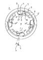
図1では、ねじフライスツール又はねじ切りバイト1が斜視図で見られる。ねじフライスツール又はねじ切りバイトは、回転軸Dを中心として回転可能な支持本体2を有する。ツール1の、左側の軸方向の端部領域には、4つのカッティングエレメント3,3´,3´´,3´´´が円周に亘って均等に配設されている。これらのカッティングエレメントは径方向内側に向けられているカッティングエッジを有する。これらのカッティングエッジによって、図示しないワークピースに雄ねじを備えることができる。カッティングエレメント3,3´,3´´,3´´´は実質的にプリズム状に形成されており、支持本体2で、径方向、軸方向及び周方向に設けられた図示しない接触面2に接触している。カッティングエレメント3,3´,3´´,3´´´を固定するために、固定エレメント4,4´,4´´,4´´´が設けられている。これらの固定エレメントはねじ結合部5,5´,5´´,5´´´によって支持本体2に取り付けられている。後で詳述するように、固定エレメント4,4´,4´´,4´´´は、支持本体2に取り付けられている状態では、カッティングエレメント3,3´,3´´,3´´´を固定している。それ故に、これらのカッティングエレメントは位置にしっかり保たれる。
In FIG. 1, the thread milling tool or
ツール1の構造に関する詳細は図2乃至4に認められる。
Details regarding the structure of the
図3から最も良く分かるように、支持本体2は2つの支持本体エレメント9及び10からなる。支持本体エレメント9はディスク状の収容部分13と、より小さい直径をもってこの収容部分に軸方向に接続しているシリンダ状の部分11とを有する。支持本体エレメント10は実質的に中空シリンダ状に形成されており、第1の支持本体エレメント9のシリンダ状の部分11を収容するための孔12を有する。支持本体エレメント10の、右の軸方向の端部には、中空締付錐体17を有するツール急速締付装置16(DIN69893による)が設けられている(図2及び3を参照せよ)。中空締付錐体17はツール1を締め付けて収容するための締付錐体である。この締付錐体では、外側錐体の他に、追加的に、内側の締付エレメントが設けられており、これらの締付エレメントは径方向外側に弾性をもって押圧し、摩擦係合を強め、外側錐体の熱膨張を補償する。
支持 As best seen in FIG. 3, the
第1の支持本体エレメント9の収容部分13は、各々のカッティングエレメント3,3´,3´´,3´´´を支持するために、軸方向に延びている各々の支持ウェブ14を有する。この支持ウェブには、各々のカッティングエレメント3,3´,3´´,3´´´が接触している。このことによって、カッティングエレメントの正確かつ安定的な保持が保証されている。
The receiving
個々のカッティングエレメント3,3´,3´´,3´´´が支持本体2に所定かつ正確に接触するように、収容部分13は、図4から最も良く見えるように、径方向の接触面6,6´,6´´,6´´´及び周方向の接触面7,7´,7´´,7´´´を有する。他方、図3には、支持本体2の支持本体エレメント10の、左側の、軸方向の端部が、軸方向の接触面15,15´,15´´,15´´´を有することが見られる。
In order that the
支持本体2を2つの支持本体エレメント9及び10によって形成することができることによって、接触面6,6´,6´´,6´´´,7,7´,7´´,7´´´及び15,15´,15´´,15´´´を形成すること、すなわち、特にフライス盤で切削し続いて研磨することが、製造技術的に特に容易な方法で可能である。この場合、支持本体が一体になっている場合と異なり、溝底は重要ではない。接触面の形成は、支持本体エレメント9及び10が取り外されている際に、なされる。
The
2つの部材すなわち支持本体エレメント9及び10を結合するために、支持本体エレメント10を加熱し及び/又は支持本体エレメント9を冷却し、次に、シリンダ状の部分11を孔12に挿入し、続いて、温度平衡を生じさせることが適切であることが明らかになった。2つの支持本体エレメント9及び10は、この方法で、熱的焼嵌め工程によって互いに結合される。このことは、特に、2つの部分すなわち支持本体エレメントが、正確な寸法で、均等な摩擦係合により及びアンバランスなしに互いに結合されていることをもたらす。この他に、当然ながら、2つの部分9及び10をねじ結合部によっても互いに結合することができる。
In order to join the two parts, the
特に図4に見られるように、カッティングエレメント3,3´,3´´,3´´´及び固定エレメント4,4´,4´´,4´´´は、自らの接触面で、回転軸Dの方向に延びておりかつ径方向Rに対し角度αを形成する面8,8´,8´´,8´´´が生じるように、形成されている。かくして、固定エレメント4,4´,4´´,4´´´の取付の際に、楔作用の発生によって、高い締付力がカッティングエレメント3,3´,3´´,3´´´に加えられ、それ故に、カッティングエレメント3,3´,3´´,3´´´が周方向及び径方向に支持本体2に取り付けられることが達成される。図4に見られるように、固定エレメント4,4´,4´´,4´´´は、夫々、カッティングエレメント3,3´,3´´,3´´´を径方向に被さる包摂部20,20´,20´´,20´´´を有する。これにより、カッティングエレメント3,3´,3´´,3´´´を支持本体2に特に良好に固定することができる。しかし、このような包摂部20,20´,20´´,20´´´は、カッティングエレメント3,3´,3´´,3´´´を支持本体2にしっかり固定するためには、必ずしも必要ではない。
As can be seen in particular in FIG. 4, the
カッティングエレメント3,3´,3´´,3´´´の切削箇所又はフライス削り箇所に冷却潤滑剤を供給するために、支持本体2及び特に2つの支持本体エレメント9及び10は中央の供給孔18(図3を参照)を有する。この供給孔は、左側の、軸方向の端部の領域で、径方向に延びる孔又は供給溝18に移行する。図4に見ることができるように、更に、リセス19,19´,19´´,19´´´が、2つの接触している面の嵌め合いを保証するために、支持本体2へのカッティングエレメント3,3´,3´´,3´´´の接触の領域に設けられている。この代わりに90°の角度を正確に形成することは技術的に不可能である。この理由から、カッティングエレメント3,3´,3´´,3´´´が最適に接触するためには、リセス19,19´,19´´,19´´´は好都合である。カッティングエレメント3,3´,3´´,3´´´と固定エレメント4,4´,4´´,4´´´との間には、夫々ギャップ21,21´,21´´,21´´´があり、このギャップは冷却潤滑剤用通路として設けられている。
In order to supply the cooling lubricant to the cutting or milling point of the
図に示したねじフライスツール又はねじ切りバイト1は、雄ねじを形成するために設けられている。従って、カッティングエレメント3,3´,3´´,3´´´のカッティングエッジは径方向内側に向けられている。しかし、全く同様に、ツールを雌ねじの形成のために用いることもできる。但し、その場合、カッティングエレメント3,3´,3´´,3´´´のカッティングエッジは径方向外側に向けられていなければならない。
ね じ The thread milling tool or
雄ねじの形成の場合には、ねじフライスツール又はねじ切りバイト1は、カッティングエレメント3,3´,3´´,3´´´の領域で釣鐘状に成形されたツールとして、従って、外からワークピースに装着することができるツールとして形成されている。形成されるねじは、それよりも大きなワークピースから側方に突出している接続ねじ(Anschlussgewinde)であってよい。このような接続ねじを、幾つかの実施の形態では、何回もの実行で、互いに比較的狭い間隔で形成されねばならないので、ツール1の外径が出来る限り小さいままであることが重要である。このことは提案された措置によって保証されている。このツールは、既知の解決策に比較して、外径の縮径を可能にする。何故ならば、従来の技術の解決策では、外径において、常に、カッティングエレメントの及び支持本体の突起の径方向の寸法が追加されるが、提案された解決策では、実際に、カッティングエレメントが外面を形成することができるからである。
In the case of the formation of external threads, the thread milling tool or the threaded
摩耗したカッティングエレメントの取扱も非常に容易である。何故ならば、カッティングエレメントを、径方向外側から及びツールの端面から軸方向に挿入することができるからである。 取 扱 Handling of worn cutting elements is also very easy. This is because the cutting element can be inserted axially from the radial outside and from the end face of the tool.
提案された実施の形態の他の利点は、スペースを取らないこと及びツールのコンパクトなデザインの他に、カッティングエレメントが、固定ねじによる固定のための孔を形成することによって弱くされることが最早ないことである。このことは特に重要である。何故ならば、カッティングエレメントは、少なくとも、脆性材料、例えば、硬質材料、HSS(高速度鋼)、CBN(立方晶窒化ホウ素)又はPKD(多結晶ダイヤモンド)からなるからである。 Another advantage of the proposed embodiment is that, besides taking up less space and a compact design of the tool, the cutting element is no longer weakened by forming holes for fixing by fixing screws. That is not. This is particularly important. This is because the cutting element consists at least of a brittle material, for example a hard material, HSS (high speed steel), CBN (cubic boron nitride) or PKD (polycrystalline diamond).
カッティングエレメントは全体として保たれており、更に、縮小して形成されることができる。何故ならば、ねじ穴のための領域を最早設ける必要がないからである。 The cutting element is kept as a whole and can be formed in a reduced size. This is because it is no longer necessary to provide an area for screw holes.
既知の解決策の場合のように、提案されたツールも、同様に、摩耗したカッティングエレメントを新品のカッティングエレメントと容易に交換することができる。その上、カッティングエレメントは、複数の切削領域を、特に、2つ、3つ又は4つの角に有することもできる。摩耗の場合には、カッティングエレメントを、90°又は180°容易に回転させることができる。それ故に、ツールは再度使用可能である。 As in the case of the known solution, the proposed tool likewise can easily replace a worn cutting element with a new cutting element. Moreover, the cutting element can also have a plurality of cutting areas, in particular at two, three or four corners. In case of wear, the cutting element can be easily rotated 90 ° or 180 °. Therefore, the tool can be used again.
記載した実施の形態は、シリンダ状の雄ねじを形成するためのねじフライスツール又はねじ切りバイトに向けられている。しかし、同様に、カッティングエレメント3,3´,3´´,3´´´のカッティングエッジに他の形状を備えることも可能である。それ故に、ねじの歯切りを形成することができるだけではない。カッティングエレメント3,3´,3´´,3´´´の切削領域は、回転軸Dに対し傾斜していることもできる。このことによって、錐形のボルトにねじを設けることも可能となる。
The described embodiments are directed to a thread milling tool or thread cutting tool for forming a cylindrical external thread. However, it is likewise possible to provide other shapes for the cutting edges of the
図5では、図2及び図3に示した左側から見た、ツールの完全な正面図が示されている。図5は図3と実質的に同一である。但し、図5には、支持本体2の外領域2´の構造が追加的に示されている。支持本体2の外領域2´に設けられたリセスの縁部は、一目瞭然であるという理由から、図4には示されていない。従って、図5は、図2及び図3に示したツールの、完全な正面図である。
FIG. 5 shows a complete front view of the tool as seen from the left side shown in FIGS. FIG. 5 is substantially the same as FIG. However, FIG. 5 additionally shows the structure of the
図6は従来の技術に基づくツールの斜視図を示している。ツールは支持本体22を有し、この支持本体には、カッティングエレメント23,23´,23´´,23´´´が取り付けられている。カッティングエレメント23´´及び23´´´は、夫々、ねじ結合部25´´及び25´´´によって、支持本体22に直接螺着されている。カッティングエレメント23及び23´も、同様に、図示しないねじ結合体によって取り付けられている。
FIG. 6 shows a perspective view of a tool according to the prior art. The tool has a
1…ねじフライスツール又はねじ切りバイト、2…支持本体、2´…支持本体の外領域、3…カッティングエレメント、3´…カッティングエレメント、3´´…カッティングエレメント、3´´´…カッティングエレメント、4…固定エレメント、4´…固定エレメント、4´´…固定エレメント、4´´´…固定エレメント、5…ねじ結合部、5´…ねじ結合部、5´´…ねじ結合部、5´´´…ねじ結合部、6…径方向の接触面、6´…径方向の接触面、6´´…径方向の接触面、6´´´…径方向の接触面、7…周方向の接触面、7´…周方向の接触面、7´´…周方向の接触面、7´´´…周方向の接触面、8…面、8´…面、8´´…面、8´´´…面、9…支持本体エレメント、10…支持本体エレメント、11…シリンダ状の部分、12…孔、13…収容部分、14…支持ウェブ、15…軸方向の接触面、15´…軸方向の接触面、15´´…軸方向の接触面、15´´´…軸方向の接触面、16…ツール急速締付装置、17…中空締付錐体、18…供給孔/供給溝、19…リセス、19´…リセス、19´´…リセス、19´´´…リセス、20…包摂部、20´…包摂部、20´´…包摂部、20´´´…包摂部、21…ギャップ、21´…ギャップ、21´´…ギャップ、21´´´…ギャップ、22…支持本体、23…カッティングエレメント、23´…カッティングエレメント、23´´…カッティングエレメント、23´´´…カッティングエレメント、25´´…ねじ結合部、25´´´…ねじ結合部、D…回転軸、R…径方向、α…角度。
DESCRIPTION OF
Claims (23)
(b)この支持本体(2)に着脱自在に取り付けられる少なくとも1つのカッティングエレメント(3,3´,3´´,3´´´)と、
(c)前記支持本体(2)に着脱自在に取り付けられる少なくとも1つの固定エレメント(4,4´,4´´,4´´´)とを具備し、
(d)前記少なくとも1つのカッティングエレメント(3,3´,3´´,3´´´)は固定ねじによる固定のための孔を有さず、
(e)前記支持本体(2)と前記少なくとも1つの固定エレメント(4,4´,4´´,4´´´)との間で及び/又は少なくとも2つの固定エレメントの間で形状係合及び/又は摩擦係合で取り付けられる、ねじフライスツール又はねじ切りバイト(1)。 (A) a support body (2) rotatable about a rotation axis (D);
(B) at least one cutting element (3, 3 ', 3 ", 3") removably attached to the support body (2);
(C) at least one fixing element (4, 4 ', 4 ", 4"") detachably attached to the support body (2);
(D) the at least one cutting element (3, 3 ', 3 ", 3"") does not have a hole for fixing by a fixing screw;
(E) positive engagement between said support body (2) and said at least one fixing element (4, 4 ', 4 ", 4"") and / or between at least two fixing elements; And / or a thread milling tool or thread cutting tool (1) mounted with frictional engagement.
(b)少なくとも1つのカッティングエレメント(3,3´,3´´,3´´´)と、
(c)少なくとも1つの結合手段、特にねじ結合部(5,5´,5´´,5´´´)によって前記支持本体(2)に着脱自在に取り付けられる少なくとも1つの固定エレメント(4,4´,4´´,4´´´)とを具備し、
(d)前記少なくとも1つのカッティングエレメント(3,3´,3´´,3´´´)は、前記支持本体(2)と前記少なくとも1つの固定エレメント(4,4´,4´´,4´´´)との間で及び/又は少なくとも2つの固定エレメントの間で形状係合及び/又は摩擦係合で及び着脱自在に取り付けられ、
(e)各々の固定エレメント(4,4´,4´´,4´´´)及び各々の結合手段(5,5´,5´´,5´´´)は、夫々、前記カッティングエレメント(3,3´,3´´,3´´´)の外側に設けられており、夫々、前記カッティングエレメント(3,3´,3´´,3´´´)を貫通しておらず、このカッティングエレメントによって囲繞されない、特に請求項1に記載のねじフライスツール又はねじ切りバイト。 (A) a support body (2) rotatable about a rotation axis (D);
(B) at least one cutting element (3, 3 ', 3 ", 3");
(C) at least one fixing element (4, 4) which is removably attached to said support body (2) by at least one coupling means, in particular a screw connection (5, 5 ', 5 ", 5"'). , 4 ″, 4 ′ ″)
(D) the at least one cutting element (3, 3 ', 3 ", 3"") comprises the support body (2) and the at least one fixing element (4, 4', 4", 4 "). '''') And / or at least two fixed elements in form and / or frictional engagement and removably mounted,
(E) Each fixing element (4, 4 ', 4 ", 4"') and each coupling means (5, 5 ', 5 ", 5"') are respectively 3, 3 ', 3 ", 3")) and do not penetrate the cutting elements (3, 3', 3 ", 3"), respectively. The thread milling tool or thread cutting tool according to claim 1, not surrounded by a cutting element.
(b)前記少なくとも1つのカッティングエレメント(3,3´,3´´,3´´´)のための径方向の接触面(6,6´,6´´,6´´´)及び周方向の接触面(7,7´,7´´,7´´´)を前記第1の支持本体エレメント(9)に形成すること、
(c)前記第1の支持本体エレメント(9)の前記シリンダ状の部分(11)を収容するための孔(12)を有する第2の支持本体エレメント(10)を形成すること、
(d)前記少なくとも1つのカッティングエレメント(3,3´,3´´,3´´´)のための軸方向の接触面(15´,15´´´)を前記第2の支持本体エレメント(10)に形成すること、
(e)前記シリンダ状の部分(11)を前記孔(12)に挿入した後に、前記第1の支持本体エレメント(9)と前記第2の支持本体エレメント(10)をしっかりと結合すること、を特徴とする請求項10に記載の又は請求項10に従属する請求項に記載のねじフライスツール又はねじ切りバイト(1)を製造する方法。 (A) a receiving part (13) for at least one cutting element (3, 3 ', 3'',3'') and a cylindrical part (10) axially connected to this receiving part (13) 11) forming a first support body element (9) having:
(B) a radial contact surface (6, 6 ', 6 ", 6"') and a circumferential direction for said at least one cutting element (3, 3 ', 3 ", 3"'); Forming a contact surface (7, 7 ', 7 ", 7"') on said first support body element (9);
(C) forming a second support body element (10) having a hole (12) for receiving the cylindrical portion (11) of the first support body element (9);
(D) providing an axial contact surface (15 ', 15''') for said at least one cutting element (3, 3 ', 3'',3'''') with said second support body element ( 10) forming;
(E) firmly connecting said first support body element (9) and said second support body element (10) after inserting said cylindrical part (11) into said hole (12); A method for manufacturing a thread milling tool or thread cutting tool (1) according to claim 10 or according to claim 10.
Applications Claiming Priority (1)
| Application Number | Priority Date | Filing Date | Title |
|---|---|---|---|
| DE10248815A DE10248815A1 (en) | 2002-10-19 | 2002-10-19 | Thread milling or cutting tool and process for its manufacture |
Publications (1)
| Publication Number | Publication Date |
|---|---|
| JP2004136436A true JP2004136436A (en) | 2004-05-13 |
Family
ID=32038776
Family Applications (1)
| Application Number | Title | Priority Date | Filing Date |
|---|---|---|---|
| JP2003358875A Pending JP2004136436A (en) | 2002-10-19 | 2003-10-20 | Screw milling cutter tool or screw cutting tool and its manufacturing method |
Country Status (4)
| Country | Link |
|---|---|
| US (1) | US20040134051A1 (en) |
| EP (1) | EP1410864A1 (en) |
| JP (1) | JP2004136436A (en) |
| DE (1) | DE10248815A1 (en) |
Cited By (2)
| Publication number | Priority date | Publication date | Assignee | Title |
|---|---|---|---|---|
| KR200457620Y1 (en) | 2011-08-17 | 2011-12-28 | 오해수 | Bur used dentistry |
| JP2021503383A (en) * | 2017-11-20 | 2021-02-12 | ハルトメタル−ウェルクゾーグファブリック ポール ホーン ゲゼルシャフト ミット ベシュレンクテル ハフツング | Waring tool |
Families Citing this family (10)
| Publication number | Priority date | Publication date | Assignee | Title |
|---|---|---|---|---|
| SE526055C2 (en) * | 2003-01-28 | 2005-06-21 | Seco Tools Ab Publ | Thread cutter and holder included in a thread cutter |
| DE102006027280B3 (en) * | 2006-06-09 | 2008-02-07 | EMUGE-Werk Richard Glimpel GmbH & Co. KG Fabrik für Präzisionswerkzeuge | Tool for machining a workpiece, cutting element and carrier body |
| DE102007060554A1 (en) * | 2007-12-13 | 2009-06-18 | EMUGE-Werk Richard Glimpel GmbH & Co. KG Fabrik für Präzisionswerkzeuge | Method for manufacturing external thread, involves placing processing workpiece and tool together in working position with rotation axis and screw thread forming area |
| DE102009038133A1 (en) * | 2009-08-13 | 2011-02-17 | Komet Group Gmbh | Milling tool, in particular thread milling tool |
| DE102012111401A1 (en) * | 2012-11-26 | 2014-05-28 | Walter Ag | bell cutter |
| CN103567558A (en) * | 2013-07-23 | 2014-02-12 | 昆山巨德泰精密机械有限公司 | Tipped permanent seat screw die with heat emission holes |
| FR3044948B1 (en) * | 2015-12-11 | 2018-05-25 | Virax Sa | DIE AND METHOD FOR REALIZING A THREAD ON A TUBE |
| CN106312458B (en) * | 2016-09-21 | 2020-03-24 | 吉林博仁科技有限责任公司 | Method for processing oil sprayer seat |
| DE102017130056A1 (en) * | 2017-12-14 | 2019-06-19 | Mirko Flam | whirling unit |
| CN109352099B (en) * | 2018-12-07 | 2020-08-07 | 西安交通大学 | Screw tap with self-lubricating cooling structure |
Family Cites Families (11)
| Publication number | Priority date | Publication date | Assignee | Title |
|---|---|---|---|---|
| US700736A (en) * | 1901-05-15 | 1902-05-27 | Ott Mergenthaler Company | Milling-machine cutter. |
| JPS4959185U (en) * | 1972-09-01 | 1974-05-24 | ||
| DE3635655A1 (en) * | 1986-10-21 | 1988-04-28 | Fette Wilhelm Gmbh | TAP DRILL |
| US5112162A (en) * | 1990-12-20 | 1992-05-12 | Advent Tool And Manufacturing, Inc. | Thread milling cutter assembly |
| US5114286A (en) * | 1991-08-13 | 1992-05-19 | Calkins Donald W | Interchangeable tool alignment system |
| DE9205275U1 (en) * | 1992-04-16 | 1992-06-17 | Emuge - Werk Richard Glimpel Fabrik Fuer Praezisionswerkzeuge Vormals Moschkau & Glimpel, 8560 Lauf, De | |
| US5873684A (en) * | 1997-03-29 | 1999-02-23 | Tool Flo Manufacturing, Inc. | Thread mill having multiple thread cutters |
| US6224299B1 (en) * | 1997-10-20 | 2001-05-01 | Laszlo Frecska | Tool with straight inserts for providing helical cutting action |
| SE517447C2 (en) * | 1999-06-29 | 2002-06-04 | Seco Tools Ab | Thread mill with cutter |
| DE19958636A1 (en) * | 1999-12-04 | 2001-06-07 | Vargus Ltd | Threaded milling tool has socket with bearing and alignment faces for tangentially holding interchangeable milling inserts |
| SE523755C2 (en) * | 2002-02-22 | 2004-05-11 | Seco Tools Ab | Cutting tools and holders |
-
2002
- 2002-10-19 DE DE10248815A patent/DE10248815A1/en not_active Ceased
-
2003
- 2003-09-23 EP EP03021421A patent/EP1410864A1/en not_active Withdrawn
- 2003-10-17 US US10/688,150 patent/US20040134051A1/en not_active Abandoned
- 2003-10-20 JP JP2003358875A patent/JP2004136436A/en active Pending
Cited By (3)
| Publication number | Priority date | Publication date | Assignee | Title |
|---|---|---|---|---|
| KR200457620Y1 (en) | 2011-08-17 | 2011-12-28 | 오해수 | Bur used dentistry |
| JP2021503383A (en) * | 2017-11-20 | 2021-02-12 | ハルトメタル−ウェルクゾーグファブリック ポール ホーン ゲゼルシャフト ミット ベシュレンクテル ハフツング | Waring tool |
| US11517967B2 (en) | 2017-11-20 | 2022-12-06 | Hartmetall-Werkzeugfabrik Paul Horn Gmbh | Whirling tool |
Also Published As
| Publication number | Publication date |
|---|---|
| EP1410864A1 (en) | 2004-04-21 |
| DE10248815A1 (en) | 2004-05-06 |
| US20040134051A1 (en) | 2004-07-15 |
Similar Documents
| Publication | Publication Date | Title |
|---|---|---|
| CN101267905B (en) | Low-vibration tool holder | |
| JP7157053B2 (en) | Disc milling cutters and kits containing such disc milling cutters | |
| KR102383746B1 (en) | A roughening tool and method for roughening a cylinder surface | |
| RU2525880C2 (en) | Milling tool with continuous fluid feed device | |
| JP2004136436A (en) | Screw milling cutter tool or screw cutting tool and its manufacturing method | |
| JP4667367B2 (en) | Tool for machine tool | |
| JP2007223041A (en) | End mill with detachable top | |
| JPH03131468A (en) | Grinding tool and spacer assembly used for said grinding tool | |
| JP2008506540A (en) | Tool adapter | |
| JP2019516574A (en) | Cutting inserts and tools for machining | |
| JP4972492B2 (en) | Brush for polishing machine | |
| JP2012515658A (en) | Device for fixing ring-shaped milling tool carriers | |
| KR20130132476A (en) | Cutting tool having a shank-mounted adjustment ring | |
| JP3579016B2 (en) | Cutting machine tools | |
| JP2009006424A (en) | Module connected to tool holder | |
| US20070226985A1 (en) | Apparatus and method for an adjustable tool holder | |
| US20210354214A1 (en) | Firmly assembled cutter holding assembly | |
| JP2008049405A (en) | Removable device of rotary tool | |
| US3471184A (en) | Arbor for machine tool | |
| JP2005153079A (en) | Device for mounting rotary grinding tool | |
| JP4475559B2 (en) | Tool holder | |
| JP5923646B1 (en) | Shrink-fitting tool holder and cutter chucking structure | |
| JP2000084783A (en) | Tool holder | |
| KR20160050372A (en) | Boring bar holder apparatus | |
| KR100855847B1 (en) | Milling chuck |