JP2004134968A - Subscriber transmission system and dynamic band assignment method for subscriber transmission system - Google Patents
Subscriber transmission system and dynamic band assignment method for subscriber transmission system Download PDFInfo
- Publication number
- JP2004134968A JP2004134968A JP2002296419A JP2002296419A JP2004134968A JP 2004134968 A JP2004134968 A JP 2004134968A JP 2002296419 A JP2002296419 A JP 2002296419A JP 2002296419 A JP2002296419 A JP 2002296419A JP 2004134968 A JP2004134968 A JP 2004134968A
- Authority
- JP
- Japan
- Prior art keywords
- packet
- subscriber
- amount
- input
- bandwidth
- Prior art date
- Legal status (The legal status is an assumption and is not a legal conclusion. Google has not performed a legal analysis and makes no representation as to the accuracy of the status listed.)
- Granted
Links
Images

Abstract
Description
【0001】
【発明の属する技術分野】
本発明は、加入者アクセスシステムのための加入者伝送装置に適用される、動的帯域割当を伴う伝送方式に関するものである。
【0002】
【従来の技術】
加入者アクセスシステムのひとつであるEPON(:Ethernet(R) Passive OpticalNetwork)システムは、複数の宅内加入者終端装置と局内加入者収容装置とから構成されている(例えば、特許文献1参照。)。
【0003】
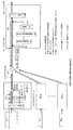
このような加入者アクセスシステムにおける、従来の動的帯域割当を伴う伝送方式を、図3及び図4を用いて説明する。図3は、従来の動的帯域割当を伴う伝送方式に対応した構成を示した構成図であり、図4は、その動作のタイムチャートである。
【0004】
この図3に記載された構成は、基本的には、ひとつの局内加入者収容装置LT1と複数の宅内加入者終端装置NT11,NT12,NT13,…,NT1nとが、スターカプラSC1を介して光ファイバで接続された構成となっている。
局内加入者収容装置LT1は、一本の光ファイバによって光分岐器であるスターカプラSC1接続されており、このスターカプラSC1に接続された複数の光ファイバが各々宅内加入者終端装置NT11,NT12,NT13,…,NT1nに接続されている。
【0005】
この様な構成を用いた加入者区間内の双方向のデータ伝送は、光PDS(:Passive Double Star)方式で行なわれる。この光PDS方式は、使用する光波長を異ならせることで、1本の光ファイバで上り方向と下り方向のデータ伝送を行う。
【0006】
宅内加入者終端装置NT11,NT12,NT13,…,NT1nから局内加入者収容装置LT1への上り方向のデータ伝送では、各宅内加入者終端装置NT11,NT12,NT13,…,NT1nが、使用する帯域を共有しており、各々が所定のタイムスロットでデータを伝送する時分割多重伝送方式で行われる。
【0007】
そして局内加入者収容装置LT1は、各宅内加入者終端装置NT11,NT12,NT13,…,NT1nへの帯域割当を一定時間間隔で動的に変更する。
【0008】
例えば図3に示すように、宅内加入者終端装置NT11へパケットP11を入力すると、宅内加入者終端装置NT11内部では、加入者間のタイムスロットに適合するため、入力パケット分割部101によって入力パケットP11をパケットP11−1,P12−1,P12−3,・・・に分割する。そして、NT状態監視部102によって生成された、宅内加入者終端装置NT11のバッファ状態を示す監視用パケットP11も付加されて、局内加入者収容装置LT1へ送出される。そして、局内加入者収容装置LT1に入力されたパケットP11−1,P12−1,P12−3,・・・は、出力パケット統合部106によって入力パケットP11に統合されて出力される。
【0009】
このような処理に際して、局内加入者収容装置LT1に入力されるパケットでは、図4の(3)に示すように、宅内加入者終端装置NT11,NT12,NT13,…,NT1nからのパケットが所定のタイムスロット(:帯域)に割り当てられている。
【0010】
そして、各宅内加入者終端装置NT11,NT12,NT13,…,NT1nが使用可能な帯域は、動的帯域割当周期t1,t2,…で区切られて、周期ごとに動的に帯域の割り当てを変更することが出来る。
【0011】
この帯域の割り当ての変更手順について、以下に説明する。
【0012】
まず、全使用帯域算出部103によって、1周期ごとに集められたパケット列ごとに、全体の帯域の使用率を算出する。そして、各NTの要求帯域演算部104が、監視用パケットより、各宅内加入者終端装置の状態、つまり、送信用バッファの残留量を算出し、その結果を基づいて、次周期の個々の宅内加入者終端装置の要求帯域を予測する。
【0013】
予測方法は、例えば、ある宅内加入者終端装置がデータ伝送していない時は、より多くのデータ伝送が必要な他の宅内加入者終端装置に自己の帯域を貸し出す処理も可能であるし、優先度の高い宅内加入者終端装置には、多くの帯域割当をすることも出来る。
【0014】
そして、申告部105が、次周期での要求帯域量を、制御パケットによって各宅内加入者終端装置へフィードバック申告して、次周期の帯域割当の制御を完了する。
【0015】
【特許文献1】
特開2002−57685号公報
【0016】
【発明が解決しようとする課題】
しかしながら、図3に示す従来の伝送方式では、以下のような問題点があった。
【0017】
まず、この加入者区間内でのデータ伝送は固定長パケットしか扱うことが出来ず、そのため、入力したパケットが分割される場合が多くなくなる。このため、パケットの遅延時間が増大するという問題があった。
【0018】
さらに、帯域の使用率の計算や予測帯域の算出などが、局内加入者収容装置内で集中処理されているため、局内加入者収容装置側の装置処理の負荷が大きくなってしまうという問題があった。
【0019】
【課題を解決するための手段】
上記の課題を解決するため、本発明の加入者伝送装置は、以下の構成を有する。
【0020】
すなわち、複数の宅内加入者終端装置と局内加入者収容装置とから構成されており、複数の宅内加入者終端装置は各々、使用帯域算出部,送出パケット制御部及び要求帯域演算部を、局内加入者収容装置は余剰帯域算出部と申告部を有する。
【0021】
そして、使用帯域算出部は、動的帯域割当周期毎にバッファに入力されている入力パケットと閾値との比較をおこなう。送出パケット制御部は、もしもバッファに入力された入力パケットが閾値より多い場合は、入力パケットを閾値分と残りに分割し、閾値分の入力パケットをひとつのパケットとして所定のパケット送出タイミングで局内加入者収容装置に送出し、分割された残りの入力パケットはバッファに蓄える。要求帯域演算部は、バッファに蓄えられている残りの入力パケットの量を情報として含んだ監視パケットを生成して局内加入者収容装置に通知すると共に、残りの入力パケットの量を最低保証帯域値と比較し、最低保証帯域値の方が大きい場合は最低保証帯域値を、残りの入力パケットの量の方が大きい場合は残りの入力パケットの量を、次の動的帯域割当周期における閾値として設定する。
【0022】
一方、余剰帯域算出部は、複数の宅内加入者終端装置各々から通知された監視パケットの情報に基づいて、各宅内加入者終端装置の帯域使用状況を集計し、申告部が、余剰帯域算出部の集計の結果に基づいて各宅内加入者終端装置の要求帯域量を決定し、制御パケットによって各宅内加入者終端装置の所定のパケット送出タイミングを、各宅内加入者終端装置へフィードバック申告する。
【0023】
【発明の実施の形態】
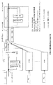
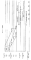
本発明の、加入者アクセスシステムにおける動的帯域割当を伴う伝送方式の実施例を、図1及び図2を用いて説明する。図1は、この実施例の構成を示した構成図であり、図2は、その動作のタイムチャートである。
【0024】
この図3に記載された構成は、基本的には従来の構成と同様に、局内加入者収容装置LT2が、一本の光ファイバによって光分岐器であるスターカプラSC2接続されており、このスターカプラSC2に接続された複数の光ファイバが各々宅内加入者終端装置NT21,NT22,NT23,…,NT2nに接続されている。そして、光PDS方式によって、加入者区間内の双方向のデータ伝送が行なわれる。
【0025】
宅内加入者終端装置NT21,NT22,NT23,…,NT2nから局内加入者収容装置LT2への上り方向のデータ伝送では、各宅内加入者終端装置NT21,NT22,NT23,…,NT2nが、使用する帯域を共有しており、各々が、局内加入者収容装置LT2によって指定された所定のタイムスロットでデータを伝送する、時分割多重伝送方式で行われる。そして局内加入者収容装置LT2は、各宅内加入者終端装置NT21,NT22,NT23,…,NT2nのデータ送出タイミングを一定時間間隔(:動的帯域割当周期)で動的に変更することで、帯域割当を変更する。
【0026】
各宅内加入者終端装置NT21,NT22,…,NT2nには、動的帯域割当周期毎に送出可能なパケット量に関して、最低保証帯域値と、この最低保証帯域値以上の範囲で可変する閾値が設定されている。
【0027】
例えば図1に示すように、宅内加入者終端装置NT21へパケットP21を入力すると、宅内加入者終端装置NT21内部で、帯域予測の前処理を行う。
【0028】
この宅内加入者終端装置NT21側での帯域予測の前処理について、以下に説明する。
【0029】
図2に示すように、宅内加入者終端装置NT21へパケットP21が入力されると、使用帯域算出部201で、閾値との比較が行われる。
【0030】
送出パケット制御部203は、もしもバッファに入力された入力パケットがその閾値より多ければ、図2の(1)に示すように、入力パケットを閾値分と残りに分割する。そして図2の(2)に示すように、局内加入者収容装置LT2で指定されたタイムスロットで、閾値分の入力パケットをひとつのパケットP21として局内加入者収容装置LT2に送出する。送出できなかった分割された残りの入力パケットはバッファに蓄える。
【0031】
次に、要求帯域演算部202が、バッファに蓄えられている残りの入力パケットの量を情報として含んだ監視パケットPc21を生成し、送出パケット制御部203を経由して局内加入者収容装置LT2に通知する。
【0032】
そして、今回の動的帯域割当周期で処理しきれなかった入力パケット量、つまり(入力パケット量−閾値)を求める。この(入力パケット量−閾値)を最低保証帯域値と比較し、最低保証帯域値の方が大きい場合は最低保証帯域値を、(入力パケット量−閾値)の方が大きい場合は(入力パケット量−閾値)を、次の動的帯域割当周期における閾値として設定する。
【0033】
それに対して、バッファに入力された入力パケット数がその閾値の範囲内であれば、すべての入力パケットをひとつのパケットP21として局内加入者収容装置LT2に送出し、その後、監視パケットPc21を送出する。そして、この場合は閾値の設定変更は行わない。
【0034】
このような帯域予測の前処理を、宅内加入者終端装置側で行うので、一度に使用可能なタイムスロットの割当を宅内加入者終端装置側で決定することが可能となる。
【0035】
そして、この割当て結果を利用することで、従来の構成とは異なり、隣接するタイムスロットをひとつのパケットで使用する選択を宅内加入者終端装置側で行うことが可能となり、可変長のデータを収容した可変長のパケットを扱って、帯域を保証する動的帯域割り当てを行うことが出来る。
【0036】
次に、局内加入者収容装置LT2側での帯域予測の処理について説明する。
【0037】
局内加入者収容装置LT2の入力部では、図2の(4)に示すように、各動的帯域割当周期t1,t2,…毎に、各宅内加入者終端装置NT2i(i=1,..., n)毎に割り振られたタイムスロットに、送出した可変長のパケットP2i及び監視パケットPc2iを配列している。なお、この配列は上述のとおり、この区間での帯域の使用効率を高めるため、可変長のパケットが隙間なく敷き詰められた構成となっている。またパケットP21のように、宅内加入者終端装置に入力されたパケットが、動的帯域割当周期を跨いで、パケットが収容されている場合もある。
【0038】
そして、局内加入者収容装置LT2では、この可変長のパケットP2iを受け、各パケットP2iの最後に監視パケットPc2iが付加されていれば、その動的帯域割当周期の終了を待つことなく、対象のパケットP2iを出力側に送出する。
【0039】
この監視パケットPc2iには、各宅内加入者終端装置NT2iのバッファに蓄えられている残りの入力パケットの数、すなわち各宅内加入者終端装置NT2iの不足する帯域の要求が含まれている。よって、余剰帯域算出部204で、この監視パケットPc2iの情報に基づいて、各宅内加入者終端装置NT2iの帯域使用状況を集計する。そして、特定の宅内加入者終端装置に帯域の余剰がある場合、帯域が不足している他の宅内加入者終端装置にこの余剰の帯域を割り振る処理を行う。
【0040】
上述の一回のパケット送出量は通り各宅内加入者終端装置NT2iで決定するので、局内加入者収容装置LT2での帯域の割り振り処理は、各宅内加入者終端装置NT2iに設定されるパケット送出タイミングを変更することで行われる。
すなわち、特定の宅内加入者終端装置に割当てられる帯域を増加させる場合はパケット送出の間隔を短く設定し、帯域を減少させる場合はパケット送出の間隔を長く設定する。
【0041】
そして、この送出タイミングの割り振り結果が、各宅内加入者終端装置NT2iの次の動的帯域割当周期におけるパケット送出タイミングとして、申告部205で生成された制御パケットPg2iによって、各宅内加入者終端装置NT2iへフィードバック申告される。なお、この制御パケットPg2iは、動的帯域割当周期ごとに、常時、固定位置に配置されている。
【0042】
以上の実施例の構成によって、各宅内加入者終端装置には最低保証帯域値が設定されており、この値を超えた範囲において動的な帯域割り当てを行う構成なので、宅内加入者終端装置側において、この最低保証帯域値に基づいた可変長のパケットの生成が容易になり、帯域の使用効率を高めることが出来る。
【0043】
さらに、閾値の変更による動的な帯域割り当ての処理の一部を、宅内加入者終端装置側で行うので、局内加入者収容装置側の装置処理の負荷増加による遅延時間の増大、および情報の劣化を防ぐことが可能となる。
【0044】
【発明の効果】
本発明によれば、各宅内加入者終端装置には最低保証帯域値が設定されており、この値を超えた範囲において動的な帯域割り当てを行う構成なので、宅内加入者終端装置側において、この最低保証帯域値に基づいた可変長のパケットの生成が容易になり、帯域の使用効率を高めることが出来る。
【0045】
さらに、閾値の変更による動的な帯域割り当ての処理の一部を、宅内加入者終端装置側で行うので、局内加入者収容装置側の装置処理の負荷増加による遅延時間の増大、および情報の劣化を防ぐことが可能となる。
【図面の簡単な説明】
【図1】実施例の構成を示す構成図である。
【図2】実施例における動的帯域割当の動作を示したタイムチャートである。
【図3】従来の動的帯域割当の動作に対応した構成を示す構成図である。
【図4】従来の動的帯域割当の動作を示したタイムチャートである。
【符号の説明】
LT1,LT2 局内加入者収容装置
NT11,…,NT1n,NT21,…,NT2n 宅内加入者終端装置
101 入力パケット分割部
102 NT状態監視部
103 全使用帯域算出部
104 要求帯域演算部
105,205 申告部
106 出力パケット統合部
SC1,SC2 スターカプラ
201 使用帯域算出部
202 要求帯域演算部
203 送出パケット制御部
204 余剰帯域算出部[0001]
TECHNICAL FIELD OF THE INVENTION
The present invention relates to a transmission scheme with dynamic band allocation applied to a subscriber transmission device for a subscriber access system.
[0002]
[Prior art]
An EPON (Ethernet (R) Passive Optical Network) system, which is one of the subscriber access systems, includes a plurality of in-home subscriber terminating devices and an in-station subscriber accommodation device (for example, see Patent Document 1).
[0003]
A conventional transmission scheme with dynamic bandwidth allocation in such a subscriber access system will be described with reference to FIGS. FIG. 3 is a configuration diagram showing a configuration corresponding to a conventional transmission system with dynamic band allocation, and FIG. 4 is a time chart of the operation.
[0004]
Basically, the configuration shown in FIG. 3 is such that one in-station subscriber accommodation device LT1 and a plurality of in-home subscriber terminal devices NT11, NT12, NT13,..., NT1n are optically connected via a star coupler SC1. It is configured to be connected by fiber.
The intra-office subscriber accommodating device LT1 is connected to a star coupler SC1, which is an optical splitter, by a single optical fiber, and a plurality of optical fibers connected to the star coupler SC1 are respectively connected to the in-home subscriber terminating devices NT11, NT12, NT12, .., NT1n.
[0005]
Bidirectional data transmission in a subscriber section using such a configuration is performed by an optical PDS (: Passive Double Star) method. In this optical PDS method, data transmission in the upstream and downstream directions is performed by one optical fiber by using different optical wavelengths.
[0006]
.., NT1n in the upstream data transmission from the home subscriber terminal devices NT11, NT12, NT13,..., NT1n to the local subscriber accommodating device LT1. , And each is performed by a time division multiplex transmission method in which data is transmitted in a predetermined time slot.
[0007]
Then, the intra-station subscriber accommodation device LT1 dynamically changes the bandwidth allocation to each of the in-home subscriber termination devices NT11, NT12, NT13,..., NT1n at fixed time intervals.
[0008]
For example, as shown in FIG. 3, when the packet P11 is input to the subscriber terminal unit NT11, it matches the time slot between subscribers in the subscriber terminal unit NT11. Are divided into packets P11-1, P12-1, P12-3,... Then, a monitoring packet P11, which is generated by the NT state monitoring unit 102 and indicates the buffer state of the subscriber terminal unit NT11, is also added thereto, and is transmitted to the local subscriber accommodation unit LT1. The packets P11-1, P12-1, P12-3,... Input to the intra-station subscriber accommodation device LT1 are integrated into the input packet P11 by the output
[0009]
In such a process, as shown in (3) of FIG. 4, packets from the home subscriber terminating devices NT11, NT12, NT13,... It is assigned to a time slot (: band).
[0010]
, NT1n are divided by the dynamic band allocation periods t1, t2,..., And the band allocation is dynamically changed for each period. You can do it.
[0011]
The procedure for changing the band allocation will be described below.
[0012]
First, the total bandwidth
[0013]
The prediction method is, for example, when a certain home subscriber terminal device is not transmitting data, it is possible to lend its own band to another home subscriber terminal device that requires more data transmission, and it is also possible to perform priority processing. A lot of bandwidth can be allocated to the high-presence subscriber terminal equipment.
[0014]
Then, the
[0015]
[Patent Document 1]
JP-A-2002-57685
[Problems to be solved by the invention]
However, the conventional transmission system shown in FIG. 3 has the following problems.
[0017]
First, data transmission within this subscriber section can handle only fixed-length packets, so that the input packets are not often divided. For this reason, there is a problem that the delay time of the packet increases.
[0018]
Furthermore, since the calculation of the band usage rate and the calculation of the predicted band are centrally processed in the intra-station subscriber accommodating apparatus, there is a problem that the processing load on the intra-station subscriber accommodating apparatus side increases. Was.
[0019]
[Means for Solving the Problems]
In order to solve the above problems, a subscriber transmission device of the present invention has the following configuration.
[0020]
That is, it is composed of a plurality of in-home subscriber terminating devices and an in-station subscriber accommodating device, and each of the plurality of in-home subscriber terminating devices includes a use band calculation unit, a transmission packet control unit, and a required band calculation unit, and an in-station subscription. The person accommodating apparatus has a surplus bandwidth calculating unit and a reporting unit.
[0021]
Then, the used bandwidth calculation unit compares the input packet input to the buffer and the threshold value for each dynamic bandwidth allocation cycle. If the number of input packets input to the buffer is larger than the threshold value, the transmission packet control unit divides the input packet into the threshold value and the remainder, and adds the threshold value input packets as one packet to the intra-office station at a predetermined packet transmission timing. It is sent to the person accommodation apparatus, and the remaining divided input packets are stored in a buffer. The required bandwidth calculation unit generates a monitoring packet including the amount of the remaining input packets stored in the buffer as information and notifies the same to the intra-station subscriber accommodating device, and determines the amount of the remaining input packets as the minimum guaranteed bandwidth value. If the minimum guaranteed bandwidth value is larger, the minimum guaranteed bandwidth value is used.If the remaining input packet amount is larger, the remaining input packet amount is used as the threshold in the next dynamic bandwidth allocation cycle. Set.
[0022]
On the other hand, the surplus bandwidth calculating unit tallies the band usage status of each of the subscriber units based on the information of the monitoring packet notified from each of the plurality of subscriber units. The required bandwidth amount of each home subscriber terminal is determined based on the result of the aggregation, and a predetermined packet transmission timing of each home subscriber termination device is reported back to each home subscriber terminal by a control packet.
[0023]
BEST MODE FOR CARRYING OUT THE INVENTION
An embodiment of a transmission system with dynamic bandwidth allocation in a subscriber access system according to the present invention will be described with reference to FIGS. FIG. 1 is a configuration diagram showing the configuration of this embodiment, and FIG. 2 is a time chart of the operation.
[0024]
In the configuration shown in FIG. 3, basically, similarly to the conventional configuration, the intra-station subscriber accommodation device LT2 is connected to a star coupler SC2, which is an optical splitter, by one optical fiber. A plurality of optical fibers connected to the coupler SC2 are respectively connected to the customer premises equipment NT21, NT22, NT23,..., NT2n. Then, bidirectional data transmission within the subscriber section is performed by the optical PDS method.
[0025]
In the upstream data transmission from the customer premises equipment NT21, NT22, NT23,..., NT2n to the customer premises equipment LT2, the bandwidth used by each of the customer premises equipment NT21, NT22, NT23,. Are performed in a time-division multiplexing transmission method in which each transmits data in a predetermined time slot specified by the intra-station subscriber accommodation device LT2. The intra-station subscriber accommodation device LT2 dynamically changes the data transmission timing of each of the in-home subscriber termination devices NT21, NT22, NT23,... Change the assignment.
[0026]
, NT2n are set with a minimum guaranteed bandwidth value and a threshold variable within a range not less than the minimum guaranteed bandwidth value with respect to the amount of packets that can be transmitted in each dynamic bandwidth allocation cycle. Have been.
[0027]
For example, as shown in FIG. 1, when the packet P21 is input to the subscriber terminal unit NT21, pre-processing of band prediction is performed inside the subscriber terminal unit NT21.
[0028]
The pre-processing of the band prediction on the side of the subscriber terminal unit NT21 will be described below.
[0029]
As shown in FIG. 2, when the packet P21 is input to the subscriber terminal unit NT21, the used
[0030]
If the number of input packets input to the buffer is larger than the threshold value, the transmission
[0031]
Next, the requested bandwidth calculation unit 202 generates a monitoring packet Pc21 including the amount of the remaining input packets stored in the buffer as information, and sends the monitoring packet Pc21 to the intra-station subscriber accommodation device LT2 via the transmission
[0032]
Then, the input packet amount that could not be processed in the current dynamic bandwidth allocation cycle, that is, (input packet amount−threshold) is obtained. This (input packet amount−threshold) is compared with the minimum guaranteed bandwidth value. If the minimum guaranteed bandwidth value is larger, the minimum guaranteed bandwidth value is used. −threshold) is set as a threshold in the next dynamic band allocation cycle.
[0033]
On the other hand, if the number of input packets input to the buffer is within the range of the threshold value, all input packets are transmitted as one packet P21 to the intra-office subscriber accommodation device LT2, and thereafter, the monitoring packet Pc21 is transmitted. . In this case, the setting of the threshold is not changed.
[0034]
Since the pre-processing of such band prediction is performed on the subscriber terminal unit side, it is possible to determine the allocation of a time slot that can be used at once at the subscriber terminal unit side.
[0035]
By using the allocation result, unlike the conventional configuration, it becomes possible for the subscriber terminal unit to select the use of adjacent time slots in one packet, and accommodate variable-length data. The dynamic bandwidth allocation that guarantees the bandwidth can be performed by handling the variable-length packet.
[0036]
Next, a description will be given of a band prediction process on the intra-station subscriber accommodation device LT2 side.
[0037]
In the input section of the intra-station subscriber accommodation device LT2, as shown in (4) of FIG. 2, the in-home subscriber terminal devices NT2i (i = 1,. , N), the transmitted variable-length packets P2i and monitoring packets Pc2i are arranged in time slots allocated for each of the above. Note that, as described above, this arrangement has a configuration in which variable-length packets are spread without gaps in order to increase the use efficiency of the band in this section. Further, as in the case of the packet P21, there is a case where a packet input to the home subscriber terminal device is accommodated over a dynamic band allocation cycle.
[0038]
Then, the intra-station subscriber accommodation device LT2 receives the variable-length packet P2i, and if the monitoring packet Pc2i is added at the end of each packet P2i, the target subscriber accommodation device LT2 does not wait for the end of the dynamic band allocation cycle, and The packet P2i is sent to the output side.
[0039]
This monitoring packet Pc2i contains the number of remaining input packets stored in the buffer of each subscriber terminal unit NT2i, that is, a request for a bandwidth shortage of each subscriber terminal unit NT2i. Therefore, the surplus
[0040]
Since the above-mentioned one-time packet transmission amount is determined by each in-home subscriber terminal device NT2i, the band allocation process in the in-house subscriber accommodation device LT2 is performed by the packet transmission timing set in each in-home subscriber terminal device NT2i. This is done by changing
That is, when increasing the bandwidth allocated to a specific subscriber terminal unit, the interval between packet transmissions is set short, and when decreasing the bandwidth, the interval between packet transmissions is set long.
[0041]
The allocation result of the transmission timing is used as the packet transmission timing in the next dynamic band allocation cycle of each subscriber subscriber terminal NT2i by the control packet Pg2i generated by the
[0042]
According to the configuration of the above-described embodiment, the minimum guaranteed bandwidth value is set in each of the home subscriber terminal devices, and dynamic bandwidth allocation is performed in a range exceeding this value. Thus, it becomes easy to generate a variable-length packet based on the minimum guaranteed bandwidth value, and it is possible to improve the bandwidth use efficiency.
[0043]
Furthermore, since part of the processing of dynamic band allocation by changing the threshold is performed on the subscriber terminal unit side, the delay time increases due to an increase in the processing load on the subscriber accommodation unit side, and information degradation. Can be prevented.
[0044]
【The invention's effect】
According to the present invention, the minimum guaranteed bandwidth value is set for each of the subscriber line termination devices, and the bandwidth is dynamically allocated in a range exceeding this value. Generation of a variable-length packet based on the minimum guaranteed band value is facilitated, and band use efficiency can be improved.
[0045]
Furthermore, since part of the processing of dynamic band allocation by changing the threshold is performed on the subscriber terminal unit side, the delay time increases due to an increase in the processing load on the subscriber accommodation unit side, and information degradation. Can be prevented.
[Brief description of the drawings]
FIG. 1 is a configuration diagram illustrating a configuration of an embodiment.
FIG. 2 is a time chart showing an operation of dynamic band allocation in the embodiment.
FIG. 3 is a configuration diagram showing a configuration corresponding to a conventional dynamic band allocation operation.
FIG. 4 is a time chart showing an operation of a conventional dynamic band allocation.
[Explanation of symbols]
LT1, LT2 Intra-office subscriber accommodation devices NT11,..., NT1n, NT21,..., NT2n In-home subscriber termination device 101 Input packet division unit 102 NT
Claims (2)
前記複数の宅内加入者終端装置は各々、
動的帯域割当周期毎にバッファに入力されている入力パケットと閾値との比較をおこなう使用帯域算出部と、
もしも前記バッファに入力された入力パケットが前記閾値より多い場合は、前記入力パケットを前記閾値分と残りに分割し、前記閾値分の入力パケットをひとつのパケットとして所定のパケット送出タイミングで前記局内加入者収容装置に送出し、前記分割された残りの入力パケットは前記バッファに蓄える、送出パケット制御部と、
前記バッファに蓄えられている残りの入力パケットの量を情報として含んだ監視パケットを生成して前記局内加入者収容装置に通知すると共に、前記残りの入力パケットの量を最低保証帯域値と比較し、前記最低保証帯域値の方が大きい場合は前記最低保証帯域値を、前記残りの入力パケットの量の方が大きい場合は前記残りの入力パケットの量を、次の動的帯域割当周期における閾値として設定する要求帯域演算部とを有し、
前記局内加入者収容装置は、
前記複数の宅内加入者終端装置各々から通知された前記監視パケットの情報に基づいて、前記各宅内加入者終端装置の帯域使用状況を集計する余剰帯域算出部と、
前記余剰帯域算出部の集計の結果に基づいて前記各宅内加入者終端装置の要求帯域量を決定し、制御パケットによって前記各宅内加入者終端装置の前記所定のパケット送出タイミングを、前記各宅内加入者終端装置へフィードバック申告する申告部とを有する
ことを特徴とする加入者伝送装置。A plurality of in-home subscriber terminating devices and an in-station subscriber accommodating device,
The plurality of home subscriber terminal devices each include:
A use bandwidth calculation unit that compares an input packet input to the buffer and a threshold for each dynamic bandwidth allocation cycle,
If the number of input packets input to the buffer is larger than the threshold value, the input packet is divided into the threshold value and the remainder, and the input packets corresponding to the threshold value are combined into one packet at a predetermined packet transmission timing to join the intra-office. A transmission packet control unit for transmitting to the person accommodation apparatus, storing the divided remaining input packets in the buffer,
A monitor packet containing the amount of the remaining input packets stored in the buffer as information is generated and notified to the intra-station subscriber accommodation device, and the amount of the remaining input packets is compared with a minimum guaranteed bandwidth value. If the minimum guaranteed bandwidth value is larger, the minimum guaranteed bandwidth value is used. If the amount of the remaining input packets is larger, the remaining input packet amount is used as a threshold value in the next dynamic bandwidth allocation cycle. And a requested bandwidth calculation unit to be set as
The in-station subscriber accommodation device,
Based on the information of the monitoring packet notified from each of the plurality of home subscriber termination devices, a surplus bandwidth calculation unit that totals the bandwidth usage status of each of the home subscriber termination devices,
A request band amount of each of the subscriber units is determined based on a result of the aggregation by the surplus bandwidth calculation unit, and a predetermined packet transmission timing of each of the subscriber units is determined by a control packet. And a reporting unit for performing a feedback declaration to the subscriber terminating device.
前記複数の宅内加入者終端装置は各々、
使用帯域算出部によって、動的帯域割当周期毎にバッファに入力されている入力パケットと閾値との比較をおこない、
もしも前記バッファに入力された入力パケットが前記閾値より多い場合は、送出パケット制御部が、前記入力パケットを前記閾値分と残りに分割し、前記閾値分の入力パケットをひとつのパケットとして所定のパケット送出タイミングで前記局内加入者収容装置に送出し、前記分割された残りの入力パケットは前記バッファに蓄え、
要求帯域演算部によって、前記バッファに蓄えられている残りの入力パケットの量を情報として含んだ監視パケットを生成して前記局内加入者収容装置に通知すると共に、前記残りの入力パケットの量を最低保証帯域値と比較し、前記最低保証帯域値の方が大きい場合は前記最低保証帯域値を、前記残りの入力パケットの量の方が大きい場合は前記残りの入力パケットの量を、次の動的帯域割当周期における閾値として設定し、
前記局内加入者収容装置は、
余剰帯域算出部によって、前記複数の宅内加入者終端装置各々から通知された前記監視パケットの情報に基づいて、前記各宅内加入者終端装置の帯域使用状況を集計し、
前記余剰帯域算出部の集計の結果に基づいて、申告部が前記各宅内加入者終端装置の要求帯域量を決定し、制御パケットによって前記各宅内加入者終端装置の前記所定のパケット送出タイミングを、前記各宅内加入者終端装置へフィードバック申告する
ことを特徴とする加入者伝送装置の動的帯域割り当て方法。A plurality of in-home subscriber terminating devices and an in-station subscriber accommodating device,
The plurality of home subscriber terminal devices each include:
The used bandwidth calculation unit compares the threshold value with the input packet input to the buffer for each dynamic bandwidth allocation cycle,
If the number of input packets input to the buffer is larger than the threshold value, the transmission packet control unit divides the input packet into the threshold value and the remainder, and the input packets for the threshold value are set as one packet as a predetermined packet. At the transmission timing, the packet is transmitted to the intra-station subscriber accommodation device, and the remaining divided input packets are stored in the buffer,
The requested bandwidth calculation unit generates a monitoring packet including the amount of the remaining input packets stored in the buffer as information and notifies the intra-subscriber subscriber accommodating device, and reduces the amount of the remaining input packets to the minimum. Compared with the guaranteed bandwidth value, when the minimum guaranteed bandwidth value is larger, the minimum guaranteed bandwidth value is used, and when the amount of the remaining input packets is larger, the remaining input packet amount is used for the next operation. As a threshold in the dynamic bandwidth allocation cycle,
The in-station subscriber accommodation device,
The surplus bandwidth calculation unit, based on the information of the monitoring packet notified from each of the plurality of home subscriber terminal devices, tabulates the band usage status of each home subscriber terminal device,
Based on the result of the aggregation of the surplus bandwidth calculation unit, the reporting unit determines the required bandwidth amount of each of the subscriber units, and the control unit transmits the predetermined packet transmission timing of each of the subscriber units, A dynamic bandwidth allocation method for a subscriber transmission device, wherein a feedback declaration is made to each of the subscriber terminal devices.
Priority Applications (1)
| Application Number | Priority Date | Filing Date | Title |
|---|---|---|---|
| JP2002296419A JP3881610B2 (en) | 2002-10-09 | 2002-10-09 | Subscriber transmission apparatus and dynamic bandwidth allocation method for subscriber transmission apparatus |
Applications Claiming Priority (1)
| Application Number | Priority Date | Filing Date | Title |
|---|---|---|---|
| JP2002296419A JP3881610B2 (en) | 2002-10-09 | 2002-10-09 | Subscriber transmission apparatus and dynamic bandwidth allocation method for subscriber transmission apparatus |
Publications (2)
| Publication Number | Publication Date |
|---|---|
| JP2004134968A true JP2004134968A (en) | 2004-04-30 |
| JP3881610B2 JP3881610B2 (en) | 2007-02-14 |
Family
ID=32286417
Family Applications (1)
| Application Number | Title | Priority Date | Filing Date |
|---|---|---|---|
| JP2002296419A Expired - Fee Related JP3881610B2 (en) | 2002-10-09 | 2002-10-09 | Subscriber transmission apparatus and dynamic bandwidth allocation method for subscriber transmission apparatus |
Country Status (1)
| Country | Link |
|---|---|
| JP (1) | JP3881610B2 (en) |
Cited By (7)
| Publication number | Priority date | Publication date | Assignee | Title |
|---|---|---|---|---|
| JP2007037194A (en) * | 2006-10-12 | 2007-02-08 | Hitachi Communication Technologies Ltd | Packet transfer device and network system |
| JP2008271611A (en) * | 2008-08-12 | 2008-11-06 | Hitachi Communication Technologies Ltd | Packet transfer device and network system |
| WO2010026767A1 (en) | 2008-09-04 | 2010-03-11 | 日本電気株式会社 | Band control method and band control device for node device |
| JP2010114822A (en) * | 2008-11-10 | 2010-05-20 | Sumitomo Electric Ind Ltd | Dynamic band allocation method and station-side apparatus |
| JP2010161566A (en) * | 2009-01-07 | 2010-07-22 | Mitsubishi Electric Corp | Device for terminating optical subscriber line, and station-side apparatus |
| JP2010232805A (en) * | 2009-03-26 | 2010-10-14 | Sumitomo Electric Ind Ltd | Communication apparatus, system and method |
| JP2011015189A (en) * | 2009-07-02 | 2011-01-20 | Sumitomo Electric Ind Ltd | Pon system and house side device of the same |
-
2002
- 2002-10-09 JP JP2002296419A patent/JP3881610B2/en not_active Expired - Fee Related
Cited By (9)
| Publication number | Priority date | Publication date | Assignee | Title |
|---|---|---|---|---|
| JP2007037194A (en) * | 2006-10-12 | 2007-02-08 | Hitachi Communication Technologies Ltd | Packet transfer device and network system |
| JP4589289B2 (en) * | 2006-10-12 | 2010-12-01 | 株式会社日立製作所 | Packet transfer device |
| JP2008271611A (en) * | 2008-08-12 | 2008-11-06 | Hitachi Communication Technologies Ltd | Packet transfer device and network system |
| JP4612713B2 (en) * | 2008-08-12 | 2011-01-12 | 株式会社日立製作所 | Packet transfer apparatus and network system |
| WO2010026767A1 (en) | 2008-09-04 | 2010-03-11 | 日本電気株式会社 | Band control method and band control device for node device |
| JP2010114822A (en) * | 2008-11-10 | 2010-05-20 | Sumitomo Electric Ind Ltd | Dynamic band allocation method and station-side apparatus |
| JP2010161566A (en) * | 2009-01-07 | 2010-07-22 | Mitsubishi Electric Corp | Device for terminating optical subscriber line, and station-side apparatus |
| JP2010232805A (en) * | 2009-03-26 | 2010-10-14 | Sumitomo Electric Ind Ltd | Communication apparatus, system and method |
| JP2011015189A (en) * | 2009-07-02 | 2011-01-20 | Sumitomo Electric Ind Ltd | Pon system and house side device of the same |
Also Published As
| Publication number | Publication date |
|---|---|
| JP3881610B2 (en) | 2007-02-14 |
Similar Documents
| Publication | Publication Date | Title |
|---|---|---|
| EP2467978B1 (en) | Method for soft bandwidth limiting in dynamic bandwidth allocation | |
| KR100605987B1 (en) | Method and system for implementing dynamic bandwidth allocation mechanism applying tree algorithm in ethernet passive optical network | |
| RU2548909C2 (en) | Bandwidth allocation method and optical line terminal | |
| EP2453613B1 (en) | Method and apparatus for allocating and prioritizing data transmission | |
| US20120294611A1 (en) | Dynamic Bandwidth Allocation for Congestion Management in PON Channel Aggregation | |
| JP5040732B2 (en) | Dynamic bandwidth allocation method and dynamic bandwidth allocation apparatus | |
| US5706288A (en) | Available bit rate scheduler | |
| KR20070058914A (en) | Bandwidth allocation device and method to guarantee qos in ethernet passive optical access network | |
| JP2007142764A (en) | Bandwidth allocation apparatus, bandwidth allocation method, and bandwidth allocation program in station side apparatus | |
| CN101984777A (en) | Passive optical network system, station equipment in passive optical network system, and a control method thereof | |
| EP1178698A2 (en) | Unused bandwidth allocation in passive optical networks | |
| JP2008270898A (en) | Optical subscriber line terminal | |
| JP2003229877A (en) | Net side transmission equipment and method for controlling variable rate traffic by allocation of dynamic band | |
| JP2004134968A (en) | Subscriber transmission system and dynamic band assignment method for subscriber transmission system | |
| US7548511B2 (en) | Apparatus and method for preserving frame sequence and distributing traffic in multi-channel link and multi-channel transmitter using the same | |
| JP6475648B2 (en) | Communication system, operation method of communication apparatus, and program | |
| JP2009010687A (en) | Pon system, and station side apparatus thereof, dynamic band allocation method, and providing method and enjoying method of dynamic band allocation service | |
| CN111988683B (en) | Bandwidth allocation method and related equipment | |
| JP5815478B2 (en) | Bandwidth allocation method and communication apparatus | |
| KR100503417B1 (en) | QoS guaranteed scheduling system in ethernet passive optical networks and method thereof | |
| JP2014011666A (en) | Method for allocating band for uplink data and communication device | |
| KR100719896B1 (en) | An Adaptive Limited Bandwidth Allocation Scheme for EPON | |
| Tykhonova | Conveyor transporting latency control in heterogeneous packet based network | |
| Monjur-Ul-Ahsan et al. | Grant Allocation Scheme with Void Filling Principle in the Multi-thread Polling based DBA Algorithm for the LR-PON System | |
| Lee et al. | Service differentiation scheme in OBS networks |
Legal Events
| Date | Code | Title | Description |
|---|---|---|---|
| A621 | Written request for application examination |
Free format text: JAPANESE INTERMEDIATE CODE: A621 Effective date: 20041220 |
|
| RD01 | Notification of change of attorney |
Free format text: JAPANESE INTERMEDIATE CODE: A7421 Effective date: 20060923 |
|
| RD02 | Notification of acceptance of power of attorney |
Free format text: JAPANESE INTERMEDIATE CODE: A7422 Effective date: 20060929 |
|
| A977 | Report on retrieval |
Free format text: JAPANESE INTERMEDIATE CODE: A971007 Effective date: 20061013 |
|
| RD04 | Notification of resignation of power of attorney |
Free format text: JAPANESE INTERMEDIATE CODE: A7424 Effective date: 20061013 |
|
| TRDD | Decision of grant or rejection written | ||
| A01 | Written decision to grant a patent or to grant a registration (utility model) |
Free format text: JAPANESE INTERMEDIATE CODE: A01 Effective date: 20061024 |
|
| A61 | First payment of annual fees (during grant procedure) |
Free format text: JAPANESE INTERMEDIATE CODE: A61 Effective date: 20061110 |
|
| R150 | Certificate of patent or registration of utility model |
Free format text: JAPANESE INTERMEDIATE CODE: R150 |
|
| FPAY | Renewal fee payment (event date is renewal date of database) |
Free format text: PAYMENT UNTIL: 20091117 Year of fee payment: 3 |
|
| FPAY | Renewal fee payment (event date is renewal date of database) |
Free format text: PAYMENT UNTIL: 20101117 Year of fee payment: 4 |
|
| FPAY | Renewal fee payment (event date is renewal date of database) |
Free format text: PAYMENT UNTIL: 20101117 Year of fee payment: 4 |
|
| FPAY | Renewal fee payment (event date is renewal date of database) |
Free format text: PAYMENT UNTIL: 20111117 Year of fee payment: 5 |
|
| FPAY | Renewal fee payment (event date is renewal date of database) |
Free format text: PAYMENT UNTIL: 20111117 Year of fee payment: 5 |
|
| FPAY | Renewal fee payment (event date is renewal date of database) |
Free format text: PAYMENT UNTIL: 20121117 Year of fee payment: 6 |
|
| FPAY | Renewal fee payment (event date is renewal date of database) |
Free format text: PAYMENT UNTIL: 20121117 Year of fee payment: 6 |
|
| FPAY | Renewal fee payment (event date is renewal date of database) |
Free format text: PAYMENT UNTIL: 20131117 Year of fee payment: 7 |
|
| LAPS | Cancellation because of no payment of annual fees |