JP2004134187A - Connector - Google Patents
Connector Download PDFInfo
- Publication number
- JP2004134187A JP2004134187A JP2002296507A JP2002296507A JP2004134187A JP 2004134187 A JP2004134187 A JP 2004134187A JP 2002296507 A JP2002296507 A JP 2002296507A JP 2002296507 A JP2002296507 A JP 2002296507A JP 2004134187 A JP2004134187 A JP 2004134187A
- Authority
- JP
- Japan
- Prior art keywords
- connector
- guide
- guide groove
- guide rib
- housing
- Prior art date
- Legal status (The legal status is an assumption and is not a legal conclusion. Google has not performed a legal analysis and makes no representation as to the accuracy of the status listed.)
- Pending
Links
Images


Classifications
-
- H—ELECTRICITY
- H01—ELECTRIC ELEMENTS
- H01R—ELECTRICALLY-CONDUCTIVE CONNECTIONS; STRUCTURAL ASSOCIATIONS OF A PLURALITY OF MUTUALLY-INSULATED ELECTRICAL CONNECTING ELEMENTS; COUPLING DEVICES; CURRENT COLLECTORS
- H01R13/00—Details of coupling devices of the kinds covered by groups H01R12/70 or H01R24/00 - H01R33/00
- H01R13/62—Means for facilitating engagement or disengagement of coupling parts or for holding them in engagement
- H01R13/627—Snap or like fastening
- H01R13/6271—Latching means integral with the housing
- H01R13/6272—Latching means integral with the housing comprising a single latching arm
Abstract
Description
【0001】
【発明の属する技術分野】
本発明は、一対のコネクタハウジングの嵌合動作がガイドされながら、相嵌合して電気的接続が行われるコネクタに関するものである。
【0002】
【従来の技術】
図5及び図6には、従来のコネクタの一例が示されている(例えば、特許文献1)。
【0003】
コネクタ50は、互いに嵌合可能な雄雌のコネクタハウジング51,55を備えている。雌型コネクタハウジング51は、機器と一体的に形成された略角筒状の周壁52を備え、周壁52の内側には雄型端子54が突出して配置されている。周壁52の上面における幅方向の中央位置には、雄型コネクタハウジング55のロックアーム58が係止可能なロック突部53が上方に突出して設けられている。
【0004】
ロック突部53の両側には、周壁52の全長にわたって前後に延出する一対のガイドリブ60,60が上方に突出して設けられている。また、周壁52の両側面にも一対のガイドリブ61,61が側方に突出して設けられている。
【0005】
雄型コネクタハウジング55は、雌型端子59を収容可能な端子収容部56と、この端子収容部56を取り囲む筒部57とが連結された構成となっている。端子収容部56と筒部57との間に、雌型コネクタハウジング51の周壁52が嵌合されるようになっている。
【0006】
筒部57の上部のうち、幅方向の中央部分にはロックアーム58が設けられている。ロックアーム58には、上下に貫通するロック孔58aが設けられており、ロック孔58aに雌型コネクタハウジング51のロック突部53が係止可能とされている。
【0007】
ロックアーム58の両側には、ガイドリブ60に対する切欠部67が設けられている。切欠部67には、両コネクタハウジング51,55が嵌合されるのに伴って、ガイドリブ60が進入されるようになっている。筒部57の両側面には、ガイド溝63を有する膨出部64が設けられている。ガイド溝63には、周壁52の両側面に設けられた一対のガイドリブ61,61が進入されるようになっている。
【0008】
雌型コネクタハウジング51に雄型コネクタハウジング55を嵌入すると、周壁52が筒部57と端子収容部56との間に進入し、ガイドリブ60が切欠部62に進入し、ガイドリブ61がガイド溝63に進入することで、両コネクタハウジング51,55の嵌合動作が行われるようになっている。
【0009】
【特許文献1】
特開2002−198127号公報(第3−4頁、第1図、第6図)
【0010】
【発明が解決しようとする課題】
しかしながら、前記従来のコネクタ50では、解決すべき以下の問題点がある。
【0011】
周壁52の4箇所に設けられたガイドリブ60,60,61,61と筒部57に設けられた切欠部62及びガイド溝63とが面で接触し、両コネクタハウジング51,55の嵌合動作が行われるため、摺動抵抗が大きくなり、円滑に嵌合を行うことができないという問題がある。
【0012】
両コネクタハウジング51,55の嵌合の際は、雄型端子54と雌型端子59とが接触するときの摺動抵抗に加えて、ガイドリブ60と切欠部62及びガイドリブ61とガイド溝63との摺動抵抗が加わり、合計された摺動抵抗が大きくなるためである。端子54,59の摺動抵抗は、多極のコネクタほど大きくなり、嵌合作業性が悪くなってしまう。摺動抵抗が大きくなり、嵌合作業性が悪くなると、コネクタ組立ラインの自動化を図ることもできなくなってしまう。
【0013】
そこで、ガイドリブ60と切欠部62及びガイドリブ61とガイド溝63との摺動抵抗を低くするため、互いのスライド面間に隙間を設けることが考えられるが、隙間を設けると嵌合動作の際に両コネクタハウジング51,55にがたつきが生じ、ガイド性が損なわれて、雄型端子54が雌型端子59をど突いたり、雄型端子54のタブ状の電気接触部が折れ曲がったり、雌型端子59の箱状の電気接触部が変形したりすることがある。
【0014】
また、コネクタ50が、自動車のエンジンルーム内や振動が生ずる家電機器などに用いられた場合には、外部振動がコネクタ50に伝わり、これによって両端子54,59が擦れ合って、擦過摩耗や擦過腐食を生ずるという問題がある。
【0015】
本発明は、上記した点に鑑み、ガイドリブとガイド溝との摺動抵抗を低減して、円滑に嵌合動作を行うことができ、コネクタの嵌合作業性を向上することができるコネクタを提供することを目的とする。
【0016】
【課題を解決するための手段】
上記目的を達成するために、請求項1記載の発明は、コネクタ嵌合方向にガイドされながら嵌合する一対のコネクタハウジングのうち、一方のコネクタハウジングの壁部に形成されたガイドリブと他方のコネクタハウジングの壁部に形成されたガイド溝とが係合し、該ガイドリブと該ガイド溝とが複数の点又は線で接触した状態で、前記一対のコネクタハウジングの嵌合動作が行われることを特徴とする。
【0017】
上記構成によれば、一対のコネクタハウジングが、コネクタ嵌合方向に直交する方向に位置決めされ、その嵌合動作がガイドされることで、一対のコネクタハウジングのがたつきが防止されるとともに、端子の誤挿入が防止されて、確実に両端子が電気的に接続される。
【0018】
そして、嵌合動作をガイドするガイドリブとガイド溝とが複数の不連続な点又は線で接触するから、コネクタ嵌合時におけるガイドリブとガイド溝との摺動抵抗が小さくなり、低嵌合力で一対のコネクタハウジングが相互に嵌合する。
【0019】
また、請求項2記載の発明は、請求項1記載のコネクタにおいて、前記ガイドリブが前記一方のコネクタハウジングの周壁に設けられ、前記ガイド溝が該周壁に外嵌される前記他方のコネクタハウジングのフード部に設けられたことを特徴とする。
【0020】
上記構成によれば、一対のコネクタハウジングの構造を複雑化させず、コネクタを肥大化することなく、簡易な嵌合構造で低嵌合力のコネクタを低コストで提供することができる。
【0021】
また、請求項3記載の発明は、請求項1又は2記載のコネクタにおいて、前記ガイドリブ又は前記ガイド溝の何れか一方のスライド面が曲面に形成され、該スライド面に摺接する他方のスライド面が平坦面に形成されたことを特徴とする。
【0022】
上記構成によれば、曲面と平坦面とが接触するから、ガイドリブとガイド溝とが線で接触し、面で接触する場合に比べて接触面積が小さくなり、摺動抵抗が低減される。
【0023】
また、請求項4記載の発明は、請求項3記載のコネクタにおいて、前記ガイドリブが断面視太鼓状に形成され、両側の太鼓面が前記ガイド溝のスライド面に接触することを特徴とする。
【0024】
上記構成によれば、ガイドリブとガイド溝とが線で接触し、コネクタ嵌合時の摺動抵抗が減少し、一対のコネクタハウジングの嵌合動作がスムーズに行われる。
【0025】
また、請求項5記載の発明は、請求項3記載のコネクタにおいて、前記曲面が、コネクタ嵌合方向に延びる波状面であることを特徴とする。
上記構成によれば、波状面と平坦面とが接触するから、ガイドリブとガイド溝とが不連続の点で接触し、面や線で接触する場合に比べて接触面積が小さくなり、摺動抵抗が著しく低減される。
【0026】
【発明の実施の形態】
以下に本発明の実施の形態の具体例を図面を用いて詳細に説明する。
図1〜4は、本発明に係るコネクタの一実施形態を示すものである。
【0027】
図1又は図2に示すように、本発明のコネクタ10は、相嵌合する雌型コネクタハウジング12と雄型コネクタハウジング20とを備えていて、一対のコネクタハウジング12,20の嵌合動作を直線的にガイドする、ガイドリブ17とガイド溝37とが複数の点又は線で接触することを特徴とするものである。
【0028】
ここで、本明細書では、雄型端子13が収容されたコネクタハウジングを雌型コネクタハウジング12と定め、雌型端子21が収容されたコネクタハウジングを雄型コネクタハウジング20と定めることとする。一対のコネクタハウジング12,20は、ともに合成樹脂材料を構成材料とし、射出成形にて一体的に成形されたものである。
【0029】
雌型コネクタハウジング12は、自動車の車両搭載機器に直付けされた待ち受け状態にある機器側のコネクタハウジングであり、雄型コネクタハウジング20のインナーハウジング26を受け入れるコネクタ嵌合室19が、環状の周壁(壁部)15の内側に形成されている。
【0030】
雄型端子13は、雄型コネクタハウジング20の端子挿通孔27に対向して配置され、コネクタ嵌合室19内でコネクタ嵌合方向前方に突出している。一対のコネクタハウジング12,20を嵌合させると、タブ状の電気接触部14が端子挿通孔27にガイドされながら雌型端子21の電気接触部22に挿入されるようになっている。
【0031】
周壁15の上壁15aの幅方向中央には、雄型コネクタハウジング20のロックアーム25に係合する係合溝16が形成されている。係合溝16の前方には、略垂直の係止面16aが形成されていて、この係止面16aにロックアーム25の先端部25aが係止されて、一対のコネクタハウジング12,20が抜け出さないように嵌合するようになっている。
【0032】
図1に示すように、周壁の両側壁15c,15cと下壁15bには、コネクタ嵌合方向に延出するガイドリブ17が外側に突出して形成されている。ガイドリブ17は、3箇所に設けられていて、雄型コネクタハウジング20のガイド溝37に係合することにより、嵌入する側の雄型コネクタハウジング20がコネクタ嵌合方向に直交する平面内において、互いに直交する2方向に位置決めされるようになっている。ガイドリブ17の数は任意であり、2個又は4個以上の数とすることもできる。
【0033】
すなわち、両側壁15c,15cに形成された一対のガイドリブ17,17により上下方向Xの位置決めが行われ、下壁に15b形成されたガイドリブ17により左右方向のYの位置決めが行われるようになっている。上壁15aには、ガイドリブは設けられていないが、係合溝16の両側にガイドリブを設けることも可能である。
【0034】
図3(a)に示すように、ガイドリブ17は、側壁15cに連なる付け根側が、細く形成されていて、ガイド溝37の両側のコーナ部37bに干渉しないようになっている。また、コーナ部37bと付け根との間には、隙間が形成されているため、ガイド溝37に対するガイドリブ17の挿入がスムーズに行われるようになっている。
【0035】
ガイドリブ17は断面視太鼓状に形成され、対向する両側面(スライド面)17a,17aは、外側に張り出す太鼓面に形成されている。このため、太鼓面がガイド溝37の対向する溝壁面(スライド面)37aに線接触した状態で、コネクタの嵌合動作が行われるようになっている。
【0036】
図3(b)は、ガイドリブ17とガイド溝37の変形例を示したものであり、ガイド溝37の溝壁面37aが凸曲面に形成され、ガイドリブ17の側面17aが平坦面に形成されている。この場合も、ガイドリブ17とガイド溝37とが線接触した状態で、コネクタの嵌合動作が行われるようになっている。この変形例では、ガイドリブ17の付け根が太いため、ガイドリブ17の強度が高まること効果がある。
【0037】
このように、ガイドリブ17とガイド溝37とが線接触することにより、コネクタ嵌合時におけるガイドリブ17とガイド溝37との摺動抵抗が小さくなり、低嵌合力で一対のコネクタハウジング12,20が相互に嵌合し、コネクタ嵌合動作が円滑に行われて、嵌合作業性が向上する。
【0038】
また、周壁15に設けられたガイドリブ17又はアウターハウジング(フード部)36に設けられたガイド溝37の何れか一方の形状を変更するだけの簡易な改良で、低嵌合力のコネクタ10を得ることができる。
【0039】
図4に示すように、本発明は、ガイドリブ17の両側面17a,17a又はガイド溝37の両溝壁面37a,37aのうち、何れか一方の面をコネクタ嵌合方向Zに延びる波状面に形成し、他方の面を平坦面に形成することも特徴としている。
【0040】
図4(a)にはガイド溝37の溝壁面37aが波状面に形成された一例が示され、図4(b)にはガイドリブ17の側面17aが波状面に形成された他の一例が示されている。このように、一方の面を波状面に形成することで、ガイドリブ17とガイド溝37とが不連続の点で接触することとなり、面や線で接触する場合に比べて接触面積を小さくでき、摺動抵抗を著しく低減することができる。
【0041】
雄型コネクタハウジング20は、電線45に接続されたハーネス側のコネクタハウジングであり、待ち受け状態にある雌型コネクタハウジング12に嵌合されるコネクタである。
【0042】
雄型コネクタハウジング20は、筒状のインナーハウジング26と、インナーハウジング26の外側を囲むアウターハウジング36とからなっている。インナーハウジング26は、その内側に端子収容室28を有していて、この端子収容室28に電線45の端部に接続された雌型端子21が収容されるようになっている。
【0043】
雌型端子21は、導電性基板を打ち抜き折り曲げ加工を経て形成され、一側に電気接触部22を有し、他側に電線接続部24を有している。電気接触部22は箱状をなし、その内側には、雄型端子13に対する弾性接触片23が湾曲形成されている。電線接続部24には、防水用のゴム栓35に挿通された電線45が圧着されている。
【0044】
ゴム栓35は、蛇腹状のチューブであり、端子収容室28の内面に密着した状態に装着されている。これにより、電線45を伝う水滴が端子収容室28に浸入することが防止されている。
【0045】
端子収容室28の長手方向中間部に位置する内壁上部からは、ハウジングランス30が前方に向けて突出形成されている。ハウジングランス30の先端部には、係止面30aが形成されていて、この係止面30aが端子収容室28に挿入された雌型端子21の電気接触部22に形成された係止部22aに当接して、雌型端子21が係止されるようになっている。
【0046】
ハウジングランス30の上方には、ハウジングランス30の撓み空間31が形成されていて、雌型端子21によってハウジングランス30が上方に押し上げられることで、雌型端子21の挿入が許容されている。この撓み空間31に、インナーハウジング26の前端部に装着されたフロントホルダ34の突出部34aが挿入されると、ハウジングランス30の撓みが規制されて雌型端子21の後抜けが防止されるようになっている。
【0047】
インナーハウジング26の奥壁側には、防水リング33が嵌着されていて、この防水リング33が周壁15の内周面に密着することで、一対のコネクタハウジング12,20間の防水が図られるようになっている。
【0048】
アウターハウジング36は、略角筒状をなし、インナーハウジング26の後半部に一体的に連なり、コネクタ嵌合方向Zに突出形成されている。アウターハウジング36の前端部は、インナーハウジング26の前端部よりコネクタ嵌合方向Z前方に突出していて、雌型コネクタハウジング12の鍔部18に対峙する。
【0049】
アウターハウジング36の内壁には、雌型コネクタハウジング12の周壁15の3箇所に突設されたガイドリブ17に対するガイド溝37が凹設されている。ガイド溝37にガイドリブ17が係合して、コネクタ嵌合動作が円滑に行われるようになっている。
【0050】
インナーハウジング26とアウターハウジング36の間の空間は、雌型コネクタハウジング12が嵌入する環状の嵌合空間42になっている。この嵌合空間42は、雌型コネクタハウジング12の周壁15が緊密に嵌合する空間に形成されている。
【0051】
コネクタ10の組立ては、雌型コネクタハウジング12に雄型コネクタハウジング20を対向させ、一対のコネクタハウジング12,20を相互に接近させてガイドリブ17にガイド溝37を係合させ、環状の嵌合空間42に周壁15を押し込むことで行われる。ガイドリブ17とガイド溝37との摺動抵抗は小さいから、一対のコネクタハウジング12,20は低嵌合力で相互に嵌合する。
【0052】
このような本実施形態によれば、雌型コネクタハウジング12の周壁15に形成されたガイドリブ17と雄型コネクタハウジング20のアウターハウジング36に形成されたガイド溝37とが不連続な点又は線で接触するから、コネクタ嵌合時のガイドリブ17とガイド溝37との摺動抵抗が小さくなり、コネクタ嵌合動作が円滑に行われて、嵌合作業性が向上する。
【0053】
【発明の効果】
以上の如く、請求項1記載の発明によれば、一対のコネクタハウジングの嵌合動作をガイドするガイドリブとガイド溝とが複数の不連続な点又は線で接触するから、コネクタ嵌合時におけるガイドリブとガイド溝との摺動抵抗が小さくなり、低嵌合力で一対のコネクタハウジングが相互に嵌合する。従って、コネクタ嵌合動作が円滑に行われて、嵌合作業性が向上する。
【0054】
また、請求項2記載の発明によれば、ガイドリブが周壁に設けられ、ガイド溝がアウターハウジングのフード部に設けられているから、一対のコネクタハウジングの構造が複雑化せず、コネクタが肥大化することを防止することができる。従って、簡易な嵌合構造で低嵌合力のコネクタを低コストで提供することができる。
【0055】
また、請求項3記載の発明によれば、一方のスライド面が曲面に形成され、他方のスライド面が平坦面に形成されているから、ガイドリブとガイド溝とが線で接触し、面で接触する場合に比べて、接触面積が小さくなり、摺動抵抗が低減される。従って、一対のコネクタハウジングの嵌合動作を円滑に行うことができ、嵌合作業性を向上することができる。
【0056】
また、請求項4記載の発明によれば、太鼓状に形成されたガイドリブの太鼓面がガイド溝の溝壁面に接触するようになっているから、ガイドリブとガイド溝とが点又は線で接触し、コネクタ嵌合時の摺動抵抗が減少する。従って、請求項1記載の効果と同等の効果を奏し、一対のコネクタハウジングの嵌合動作を円滑に行うことができる。
【0057】
また、請求項5記載の発明によれば、一方のスライド面が波状面であり、他方のスライド面が平坦面であるから、ガイドリブとガイド溝とが不連続の点で接触し、面や線で接触する場合に比べて接触面積が小さくなり、摺動抵抗が著しく低減される。従って、一対のコネクタハウジングの嵌合動作をより一層円滑に行うことができ、嵌合作業性を向上することができる。
【図面の簡単な説明】
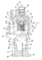
【図1】本発明の一実施形態に係るコネクタの組立横断面図である。
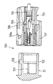
【図2】図1に示すコネクタを分解縦断面図である。
【図3】図1に示すコネクタのガイドリブとガイド溝の横断面図であり、(a)は太鼓状のガイドリブがガイド溝の溝壁面に接触している状態を示し、(b)はガイドリブが両側に凸曲面を有するガイド溝に接触している状態を示す図である。
【図4】図1に示すコネクタのガイドリブとガイド溝の縦断面図であり、(a)は平坦面を有するガイドリブが波状面を有するガイド溝に接触している状態を示し、(b)は波状面を有するガイドリブが平坦面を有するガイド溝に接触している状態を示す図である。
【図5】従来のコネクタの一例を示す分解横断面図である。
【図6】図5に示すコネクタの組立縦断面図である。
【符号の説明】
10 コネクタ
12 雌型コネクタハウジング
15 周壁
17 ガイドリブ
17a 側面(スライド面)
20 雄型コネクタハウジング
26 インナーハウジング
36 アウターハウジング(フード部)
37 ガイド溝
37a 溝壁面(スライド面)[0001]
TECHNICAL FIELD OF THE INVENTION
TECHNICAL FIELD The present invention relates to a connector in which a pair of connector housings are mated and electrically connected to each other while a fitting operation of the connector housings is guided.
[0002]
[Prior art]
5 and 6 show an example of a conventional connector (for example, Patent Document 1).
[0003]
The
[0004]
On both sides of the
[0005]
The
[0006]
A
[0007]
Notches 67 for the
[0008]
When the
[0009]
[Patent Document 1]
JP-A-2002-198127 (pages 3-4, FIG. 1, FIG. 6)
[0010]
[Problems to be solved by the invention]
However, the
[0011]
The guide ribs 60, 60, 61, 61 provided at four locations on the
[0012]
When the two
[0013]
In order to reduce the sliding resistance between the
[0014]
Further, when the
[0015]
In view of the above, the present invention provides a connector capable of reducing the sliding resistance between a guide rib and a guide groove, performing a smooth fitting operation, and improving the workability of the connector fitting. The purpose is to do.
[0016]
[Means for Solving the Problems]
In order to achieve the above object, according to the present invention, a guide rib formed on a wall portion of one of the connector housings and a connector of the other connector among a pair of connector housings that are fitted while being guided in the connector fitting direction. The pair of connector housings are engaged with each other in a state where the guide grooves formed in the wall of the housing are engaged with each other and the guide ribs and the guide grooves are in contact with each other at a plurality of points or lines. And
[0017]
According to the above configuration, the pair of connector housings are positioned in a direction orthogonal to the connector fitting direction, and the fitting operation is guided, so that the pair of connector housings are prevented from rattling and the terminal Erroneous insertion is prevented, and both terminals are reliably electrically connected.
[0018]
Further, since the guide rib and the guide groove that guide the fitting operation contact at a plurality of discontinuous points or lines, the sliding resistance between the guide rib and the guide groove at the time of connector fitting is reduced, and the pair of guide ribs with a low fitting force is formed. Connector housings are fitted to each other.
[0019]
According to a second aspect of the present invention, in the connector according to the first aspect, the guide rib is provided on a peripheral wall of the one connector housing, and the guide groove is externally fitted to the peripheral wall. It is characterized by being provided in the section.
[0020]
According to the above configuration, a connector having a simple fitting structure and a low fitting force can be provided at low cost without complicating the structure of the pair of connector housings and without increasing the size of the connectors.
[0021]
According to a third aspect of the present invention, in the connector according to the first or second aspect, one of the guide ribs and the guide groove has a curved slide surface, and the other slide surface slidingly contacting the slide surface is formed. It is characterized by being formed on a flat surface.
[0022]
According to the above configuration, since the curved surface and the flat surface are in contact with each other, the guide rib and the guide groove are in contact with each other with a line, and the contact area is smaller than in the case where they are in contact with each other, and the sliding resistance is reduced.
[0023]
According to a fourth aspect of the present invention, in the connector according to the third aspect, the guide rib is formed in a drum shape in cross section, and the drum surfaces on both sides contact the slide surface of the guide groove.
[0024]
According to the above configuration, the guide rib and the guide groove come into contact with each other with a line, the sliding resistance at the time of connector fitting is reduced, and the fitting operation of the pair of connector housings is performed smoothly.
[0025]
The invention according to
According to the above configuration, the corrugated surface and the flat surface are in contact with each other, so that the guide rib and the guide groove are in contact at a discontinuous point, and the contact area is smaller than in the case where the guide rib and the guide groove are in contact with each other, and the sliding resistance Is significantly reduced.
[0026]
BEST MODE FOR CARRYING OUT THE INVENTION
Hereinafter, specific examples of the embodiments of the present invention will be described in detail with reference to the drawings.
1 to 4 show an embodiment of the connector according to the present invention.
[0027]
As shown in FIG. 1 or FIG. 2, the
[0028]
Here, in this specification, the connector housing accommodating the
[0029]
The
[0030]
The
[0031]
An engaging
[0032]
As shown in FIG. 1, guide
[0033]
That is, positioning in the vertical direction X is performed by a pair of
[0034]
As shown in FIG. 3 (a), the
[0035]
The
[0036]
FIG. 3B shows a modified example of the
[0037]
Since the
[0038]
Further, the
[0039]
As shown in FIG. 4, according to the present invention, one of the two
[0040]
FIG. 4A shows an example in which the
[0041]
The
[0042]
The
[0043]
The
[0044]
The
[0045]
A
[0046]
Above the
[0047]
A
[0048]
The
[0049]
On the inner wall of the
[0050]
The space between the
[0051]
To assemble the
[0052]
According to this embodiment, the
[0053]
【The invention's effect】
As described above, according to the first aspect of the present invention, the guide ribs for guiding the fitting operation of the pair of connector housings and the guide grooves contact at a plurality of discontinuous points or lines. The sliding resistance between the connector housing and the guide groove is reduced, and the pair of connector housings are fitted to each other with a low fitting force. Therefore, the connector fitting operation is performed smoothly, and the fitting workability is improved.
[0054]
According to the second aspect of the present invention, since the guide rib is provided on the peripheral wall and the guide groove is provided on the hood portion of the outer housing, the structure of the pair of connector housings is not complicated, and the connector is enlarged. Can be prevented. Therefore, a connector having a simple fitting structure and low fitting force can be provided at low cost.
[0055]
According to the third aspect of the present invention, one of the slide surfaces is formed as a curved surface, and the other slide surface is formed as a flat surface. The contact area is smaller than in the case where the sliding is performed, and the sliding resistance is reduced. Therefore, the fitting operation of the pair of connector housings can be performed smoothly, and the fitting workability can be improved.
[0056]
According to the fourth aspect of the present invention, since the drum surface of the guide rib formed in a drum shape comes into contact with the groove wall surface of the guide groove, the guide rib and the guide groove contact with each other at a point or a line. In addition, the sliding resistance when the connector is fitted is reduced. Therefore, the same effect as that of the first aspect is obtained, and the fitting operation of the pair of connector housings can be performed smoothly.
[0057]
According to the fifth aspect of the present invention, one of the slide surfaces is a wavy surface, and the other is a flat surface. The contact area is smaller than in the case where the contact is made, and the sliding resistance is significantly reduced. Therefore, the fitting operation of the pair of connector housings can be performed more smoothly, and the fitting workability can be improved.
[Brief description of the drawings]
FIG. 1 is an assembled cross-sectional view of a connector according to an embodiment of the present invention.
FIG. 2 is an exploded vertical sectional view of the connector shown in FIG.
FIGS. 3A and 3B are cross-sectional views of a guide rib and a guide groove of the connector shown in FIG. 1, wherein FIG. It is a figure showing the state where it has contacted the guide groove which has a convex curved surface on both sides.
FIGS. 4A and 4B are longitudinal sectional views of a guide rib and a guide groove of the connector shown in FIG. 1, wherein FIG. It is a figure showing the state where the guide rib which has a wavy surface has contacted the guide groove which has a flat surface.
FIG. 5 is an exploded cross-sectional view showing an example of a conventional connector.
6 is an assembled vertical sectional view of the connector shown in FIG.
[Explanation of symbols]
10
20
37
Claims (5)
Priority Applications (4)
| Application Number | Priority Date | Filing Date | Title |
|---|---|---|---|
| JP2002296507A JP2004134187A (en) | 2002-10-09 | 2002-10-09 | Connector |
| US10/680,140 US6910916B2 (en) | 2002-10-09 | 2003-10-08 | Connector |
| DE10346925A DE10346925A1 (en) | 2002-10-09 | 2003-10-09 | Interconnects |
| FR0311815A FR2845832B1 (en) | 2002-10-09 | 2003-10-09 | CONNECTOR |
Applications Claiming Priority (1)
| Application Number | Priority Date | Filing Date | Title |
|---|---|---|---|
| JP2002296507A JP2004134187A (en) | 2002-10-09 | 2002-10-09 | Connector |
Publications (1)
| Publication Number | Publication Date |
|---|---|
| JP2004134187A true JP2004134187A (en) | 2004-04-30 |
Family
ID=32040767
Family Applications (1)
| Application Number | Title | Priority Date | Filing Date |
|---|---|---|---|
| JP2002296507A Pending JP2004134187A (en) | 2002-10-09 | 2002-10-09 | Connector |
Country Status (4)
| Country | Link |
|---|---|
| US (1) | US6910916B2 (en) |
| JP (1) | JP2004134187A (en) |
| DE (1) | DE10346925A1 (en) |
| FR (1) | FR2845832B1 (en) |
Cited By (5)
| Publication number | Priority date | Publication date | Assignee | Title |
|---|---|---|---|---|
| JP2009064719A (en) * | 2007-09-07 | 2009-03-26 | Sumitomo Wiring Syst Ltd | Watertight connector |
| JP2009266781A (en) * | 2008-04-30 | 2009-11-12 | Sumitomo Wiring Syst Ltd | Connector for substrate, and mounting structure of connector for substrate |
| JP2010205543A (en) * | 2009-03-03 | 2010-09-16 | Yazaki Corp | Connector |
| JP2012059565A (en) * | 2010-09-09 | 2012-03-22 | Yazaki Corp | Chattering restriction connector during fitting |
| JP2012134104A (en) * | 2010-12-24 | 2012-07-12 | Yazaki Corp | Connector |
Families Citing this family (10)
| Publication number | Priority date | Publication date | Assignee | Title |
|---|---|---|---|---|
| US7144277B2 (en) * | 2004-09-09 | 2006-12-05 | Hon Hai Precision Ind. Co., Ltd. | Electrical connector with guidance face |
| US7594827B2 (en) * | 2006-11-17 | 2009-09-29 | Nintendo Co., Ltd. | Secure and/or lockable connecting arrangement for video game system |
| JP5308650B2 (en) * | 2007-10-23 | 2013-10-09 | サンデン株式会社 | Electric compressor terminal device |
| DE102008000188A1 (en) * | 2008-01-30 | 2009-08-06 | Robert Bosch Gmbh | Interface element, interface element holder and electrical appliance |
| US7914318B2 (en) * | 2008-11-25 | 2011-03-29 | GM Global Technology Operations LLC | Electrical connector |
| JP5723726B2 (en) * | 2011-08-24 | 2015-05-27 | 矢崎総業株式会社 | Connector with cover |
| EP2629377B1 (en) * | 2012-02-16 | 2020-06-17 | MD Elektronik GmbH | Cable for transferring signals |
| JP5854281B2 (en) * | 2012-10-15 | 2016-02-09 | 住友電装株式会社 | Spring lock type connector |
| JP6125891B2 (en) * | 2013-05-07 | 2017-05-10 | 矢崎総業株式会社 | Terminal bracket holding structure |
| CN109149320A (en) * | 2018-09-20 | 2019-01-04 | 高怡达科技(深圳)有限公司 | A kind of changeover plug, power supply adaptor processing method and changeover plug, power supply adaptor |
Family Cites Families (6)
| Publication number | Priority date | Publication date | Assignee | Title |
|---|---|---|---|---|
| US4376565A (en) * | 1981-02-17 | 1983-03-15 | Amp Incorporated | Electrical connector keying means |
| US5125850A (en) * | 1991-11-27 | 1992-06-30 | Amp Incorporated | Strain relief for an electrical connector |
| JPH10241790A (en) | 1997-02-21 | 1998-09-11 | Yazaki Corp | Fitting structure of connector housing |
| TW417892U (en) * | 1999-06-15 | 2001-01-01 | Hon Hai Prec Ind Co Ltd | Penetrating type connector |
| JP3552641B2 (en) | 2000-04-04 | 2004-08-11 | 住友電装株式会社 | connector |
| JP2002198127A (en) | 2000-12-25 | 2002-07-12 | Sumitomo Wiring Syst Ltd | Connector |
-
2002
- 2002-10-09 JP JP2002296507A patent/JP2004134187A/en active Pending
-
2003
- 2003-10-08 US US10/680,140 patent/US6910916B2/en not_active Expired - Fee Related
- 2003-10-09 FR FR0311815A patent/FR2845832B1/en not_active Expired - Fee Related
- 2003-10-09 DE DE10346925A patent/DE10346925A1/en not_active Ceased
Cited By (6)
| Publication number | Priority date | Publication date | Assignee | Title |
|---|---|---|---|---|
| JP2009064719A (en) * | 2007-09-07 | 2009-03-26 | Sumitomo Wiring Syst Ltd | Watertight connector |
| JP2009266781A (en) * | 2008-04-30 | 2009-11-12 | Sumitomo Wiring Syst Ltd | Connector for substrate, and mounting structure of connector for substrate |
| JP2010205543A (en) * | 2009-03-03 | 2010-09-16 | Yazaki Corp | Connector |
| JP2012059565A (en) * | 2010-09-09 | 2012-03-22 | Yazaki Corp | Chattering restriction connector during fitting |
| JP2012134104A (en) * | 2010-12-24 | 2012-07-12 | Yazaki Corp | Connector |
| KR101471597B1 (en) * | 2010-12-24 | 2014-12-10 | 야자키 소교 가부시키가이샤 | Connector |
Also Published As
| Publication number | Publication date |
|---|---|
| US20040072465A1 (en) | 2004-04-15 |
| US6910916B2 (en) | 2005-06-28 |
| FR2845832A1 (en) | 2004-04-16 |
| DE10346925A1 (en) | 2004-05-13 |
| FR2845832B1 (en) | 2005-04-15 |
Similar Documents
| Publication | Publication Date | Title |
|---|---|---|
| US7347710B2 (en) | Electric wire connector having a lock securing mechanism | |
| JP3494885B2 (en) | Mating connector | |
| JP2004134187A (en) | Connector | |
| JP2007324029A (en) | Terminal for electric connection, and connector using it | |
| US6676433B1 (en) | Connector | |
| JP6375246B2 (en) | Connector mating structure | |
| US10283902B2 (en) | Waterproof structure for connector | |
| JP2004146182A (en) | Connector | |
| JP3899016B2 (en) | connector | |
| JP2005203307A (en) | Connector | |
| JP6224041B2 (en) | Connector waterproof structure | |
| JP2004139875A (en) | Female terminal | |
| JP5947661B2 (en) | connector | |
| JP2004178823A (en) | Receptacle connector with latch arm, and plug connector connected to the same | |
| JP2004186078A (en) | Connector | |
| JP2008276993A (en) | Connector | |
| JP4871628B2 (en) | connector | |
| US6939170B2 (en) | Connector | |
| JP2005044598A (en) | Terminal fitting | |
| US20230102502A1 (en) | Connector | |
| JP6227600B2 (en) | Connector waterproof structure | |
| JP2007134197A (en) | Connector | |
| JP4332082B2 (en) | connector | |
| JP2021044196A (en) | Connector and connector assembly | |
| JP2012221578A (en) | Connector |
Legal Events
| Date | Code | Title | Description |
|---|---|---|---|
| A621 | Written request for application examination |
Free format text: JAPANESE INTERMEDIATE CODE: A621 Effective date: 20050126 |
|
| A977 | Report on retrieval |
Free format text: JAPANESE INTERMEDIATE CODE: A971007 Effective date: 20060607 |
|
| A131 | Notification of reasons for refusal |
Free format text: JAPANESE INTERMEDIATE CODE: A131 Effective date: 20060620 |
|
| A521 | Written amendment |
Free format text: JAPANESE INTERMEDIATE CODE: A523 Effective date: 20060811 |
|
| A131 | Notification of reasons for refusal |
Free format text: JAPANESE INTERMEDIATE CODE: A131 Effective date: 20070213 |
|
| A521 | Written amendment |
Free format text: JAPANESE INTERMEDIATE CODE: A523 Effective date: 20070416 |
|
| A02 | Decision of refusal |
Free format text: JAPANESE INTERMEDIATE CODE: A02 Effective date: 20070807 |