JP2004128808A - Method and apparatus for image processing - Google Patents
Method and apparatus for image processing Download PDFInfo
- Publication number
- JP2004128808A JP2004128808A JP2002288877A JP2002288877A JP2004128808A JP 2004128808 A JP2004128808 A JP 2004128808A JP 2002288877 A JP2002288877 A JP 2002288877A JP 2002288877 A JP2002288877 A JP 2002288877A JP 2004128808 A JP2004128808 A JP 2004128808A
- Authority
- JP
- Japan
- Prior art keywords
- image
- image data
- unit
- data
- output
- Prior art date
- Legal status (The legal status is an assumption and is not a legal conclusion. Google has not performed a legal analysis and makes no representation as to the accuracy of the status listed.)
- Pending
Links
Images


Abstract
Description
【0001】
【発明の属する技術分野】
本発明は、画像データの圧縮及び伸長を行う画像処理方法に関する。
【0002】
【従来の技術】
従来から、カラー画像データを取り扱う際には、そのデータ量の大きさが問題となっていた。例えば、白黒画像を表現するために十分な二値画像に対して、RGBそれぞれ8ビットからなる標準的なカラー画像では、同じ大きさの画像を表すために24倍のデータ量が必要となってしまう。従って、画像データをハードディスク、メモリ等の記憶装置に保存しておく場合、同じ枚数のカラー画像データを保存しておくためには白黒画像の24倍の記憶容量が必要になる。
【0003】
すなわち、単純には、カラー画像を取り扱う際には、白黒画像を取り扱う際の24倍のメモリ容量及びハードディスク容量が必要になるということであり、このことは大きなコストアップにつながってしまう。そのため、従来から、画像データに圧縮処理を施し、データ容量を小さくすることで機器等に搭載するメモリ及びハードディスクに必要な記憶容量を少なくし、コストアップを抑えるという手法がとられている。
【0004】
【発明が解決しようとする課題】
しかしながら、画像データの圧縮処理においてJPEG等の不可逆圧縮方式を利用した場合、圧縮による画質の劣化が発生し、圧縮率を高める一方で画像劣化が著しくなるという問題があった。また、画像データの拡大・縮小処理を行うためにディジタル変倍処理を行う場合にも、データの補完誤差による画像劣化が発生する。従って、ディジタル変倍を行った画像データに対してさらに不可逆圧縮を施すような場合には、もとの画像データに比して特に大きな画質の劣化が生じてしまうという問題があった。
【0005】
本発明は、このような事情を考慮してなされたものであり、圧縮画像データの符号量を制御して、ディジタル変倍処理や解像度変換処理と画像圧縮処理で生じる画質の劣化を抑えることができる画像処理方法を提供することを目的とする。
【0006】
【課題を解決するための手段】
この課題を解決するため本発明は、後述する実施態様に従えば以下の構成を特徴とする。
【0007】
[発明1] 画像データを入力する入力手段と、
前記画像データを所定の符号化パラメータで符号化して符号化データを生成する符号化手段と、
前記符号化データを復号化して復号画像データを生成する復号化手段と、
前記復号画像データを出力する出力手段と
を備える画像処理装置の画像処理方法であって、
前記符号化データを第1の格納手段に格納する第1の格納工程と、
前記出力手段から出力される前記復号画像データの出力形式を指定する指定工程と、
前記指定工程によって指定された前記出力形式に基づいて、前記符号化パラメータを決定する符号化パラメータ決定工程と、
前記指定工程によって指定された前記出力形式に基づいて、前記第1の格納手段に格納された前記符号化データを変換する変換工程と、
前記変換工程で変換された符号化データを第2の格納手段に格納する第2の格納工程と、
前記第2の格納手段に格納された前記符号化データを復号化する復号化工程と
を有することを特徴とする画像処理方法。
【0008】
[発明2] 前記変換工程が、
前記第1の格納手段に格納された前記符号化データを復号化して第2の復号化データを生成する第2の復号化工程と、
前記第2の復号化工程で復号化された前記第2の復号化データを前記出力形式に基づいて変換する第2の変換工程と、
前記第2の変換工程で変換された前記第2の復号化データを符号化して符号化データを生成する第2の符号化工程と
を有することを特徴とする発明1記載の画像処理方法。
【0009】
[発明3] 前記第2の変換工程が、画像回転、画像変倍、色空間変換、又は二値化処理を行って前記第2の復号化データをディジタル変換することを特徴とする発明2記載の画像処理方法。
【0010】
[発明4] 前記符号化パラメータ決定工程が、前記出力手段から出力される前記復号画像データと前記入力手段から入力される前記画像データとの倍率又は解像度の比率に基づいて前記符号化パラメータを決定することを特徴とする発明1から3までのいずれか1項に記載の画像処理方法。
【0011】
[発明5] 前記指定工程が、前記出力手段から出力される前記復号画像データの前記出力形式に基づいて、前記入力手段から入力される前記画像データの画像領域を決定し、
前記画像データのうち、前記指定工程によって決定された所定領域のみを前記入力手段に入力させる入力制御工程と
をさらに有することを特徴とする発明1から4までのいずれか1項に記載の画像処理方法。
【0012】
[発明6] 前記符号化手段に、前記出力形式に基づいて決定された圧縮率の量子化テーブルを用いて、前記画像データを圧縮符号化させる符号化制御工程をさらに有することを特徴とする発明1から5までのいずれか1項に記載の画像処理方法。
【0013】
[発明7] 前記指定工程が、前記画像データの拡大率と前記復号画像データの出力サイズとを出力形式として指定し、
前記入力制御工程が、前記出力サイズと前記拡大率に基づく前記画像データの領域のみを前記入力手段に等倍率で入力させ、
前記符号化パラメータ決定工程が、前記拡大率に基づいて前記符号化パラメータを決定し、
前記変換工程が、前記拡大率に基づいて符号化データを変換する
ことを特徴とする発明1記載の画像処理方法。
【0014】
[発明8] 画像データを入力する入力手段と、
前記画像データを所定の符号化パラメータで符号化して符号化データを生成する符号化手段と、
前記符号化データを復号化して復号画像データを生成する復号化手段と、
前記復号画像データを出力する出力手段と
を備える画像処理装置であって、
前記符号化データを格納する第1の格納手段と、
前記出力手段から出力される前記復号画像データの出力形式を指定する指定手段と、
前記指定手段によって指定された前記出力形式に基づいて、前記符号化パラメータを決定する符号化パラメータ決定手段と、
前記指定手段によって指定された前記出力形式に基づいて、前記第1の格納手段に格納された前記符号化データを変換する変換手段と、
前記変換手段で変換された符号化データを格納する第2の格納手段と
をさらに備え、
前記復号化手段が、前記第2の格納手段に格納された前記符号化データを復号化する
ことを特徴とする画像処理装置。
【0015】
[発明9] 前記変換手段が、
前記第1の格納手段に格納された前記符号化データを復号化して第2の復号化データを生成する第2の復号化手段と、
前記第2の復号化手段で復号化された前記第2の復号化データを前記出力形式に基づいて変換する第2の変換手段と、
前記第2の変換手段で変換された前記第2の復号化データを符号化して符号化データを生成する第2の符号化手段と
を備えることを特徴とする発明8記載の画像処理装置。
【0016】
[発明10] 前記第2の変換手段が、画像回転、画像変倍、色空間変換、又は二値化処理を行って前記第2の復号化データをディジタル変換することを特徴とする発明9記載の画像処理装置。
【0017】
[発明11] 前記符号化パラメータ決定手段が、前記出力手段から出力される前記復号画像データと前記入力手段から入力される前記画像データとの倍率又は解像度の比率に基づいて前記符号化パラメータを決定することを特徴とする発明8から10までのいずれか1項に記載の画像処理装置。
【0018】
[発明12] 前記指定手段が、前記出力手段から出力される前記復号画像データの前記出力形式に基づいて、前記入力手段から入力される前記画像データの画像領域を決定し、
前記入力手段が、前記画像データのうち、前記指定手段によって決定された前記画像領域のみを入力する
ことを特徴とする発明8から11までのいずれか1項に記載の画像処理装置。
【0019】
[発明13] 前記符号化手段が、前記出力形式に基づいて決定された圧縮率の量子化テーブルを用いて、前記画像データを圧縮符号化することを特徴とする発明8から12までのいずれか1項に記載の画像処理装置。
【0020】
[発明14] 前記指定手段が、前記画像データの拡大率と前記復号画像データの出力サイズとを出力形式として指定し、
前記入力手段が、前記出力サイズと前記拡大率に基づく前記画像データの所定領域のみを等倍率で入力し、
前記符号化パラメータ決定手段が、前記拡大率に基づいて前記符号化パラメータを決定し、
前記変換手段が、前記拡大率に基づいて符号化データを変換する
ことを特徴とする発明8記載の画像処理装置。
【0021】
[発明15] 画像データを入力する入力手段と、
前記画像データを所定の符号化パラメータで符号化して符号化データを生成する符号化手段と、
前記符号化データを復号化して復号画像データを生成する復号化手段と、
前記復号画像データを出力する出力手段と
を備えるコンピュータに、
前記符号化データを第1の格納手段に格納する第1の格納手順と、
前記出力手段から出力される前記復号画像データの出力形式を指定する指定手順と、
前記指定手順によって指定された前記出力形式に基づいて、前記符号化パラメータを決定する符号化パラメータ決定手順と、
前記指定手順によって指定された前記出力形式に基づいて、前記第1の格納手段に格納された前記符号化データを変換する変換手順と、
前記変換手順で変換された符号化データを第2の格納手段に格納する第2の格納手順と、
前記第2の格納手段に格納された前記符号化データを復号化する復号化手順と
を実行させるためのプログラム。
【0022】
[発明16] 発明15記載のプログラムを格納することを特徴とするコンピュータ読み取り可能な記録媒体。
【0023】
上記本発明の構成にかかる理由は以下の記載から明らかになるであろう。
【0024】
【発明の実施の形態】
以下、図面を参照して、本発明の一実施形態に係る画像入出力システムについて説明する。
【0025】
<画像入出力システム全体の説明>
図1は、本発明の一実施形態に係る画像入出力システム全体の概略構成を示すブロック図である。図1に示すように、画像入出力システム100において、リーダー部(画像入力装置)200は、原稿画像を光学的に読み取り、それを画像データに変換する。リーダー部200は、原稿画像を読み取るための機能を持つスキャナユニット210と、原稿用紙を搬送するための機能を持つ原稿給紙ユニット250とから構成される。
【0026】
また、プリンタ部(画像出力装置)300は、記録紙を搬送し、その上に画像データを可視画像として印字して装置外に排紙する。プリンタ部300は、複数種類の記録紙カセットを持つ給紙ユニット360と、画像データを記録紙に転写し、定着させる機能を持つマーキングユニット310と、印字された記録紙をソートし、ステイプルして装置外へ出力する機能を持つ排紙ユニット370とで構成される。
【0027】
制御装置110は、リーダー部200とプリンタ部300とに電気的に接続され、さらにLAN等のネットワーク400を介して、ホストコンピュータ401、402等に接続されている。制御装置110は、リーダー部200を制御して原稿の画像データを読み込み、プリンタ部300を制御して画像データを記録用紙に出力してコピー機能を提供する。また、制御装置110は、リーダー部200から読み取った画像データをコードデータに変換し、ネットワーク400を介してホストコンピュータ401、402へ送信するスキャナ機能、ホストコンピュータ401、402からネットワーク400を介して受信したコードデータを画像データに変換し、プリンタ部300に出力するプリンタ機能を提供する。
【0028】
操作部150は液晶タッチパネルで構成され、制御装置110に接続され、画像入出力システム100を操作するためのユーザインタフェース(I/F)を提供する。
【0029】
図2は、本実施形態における画像入出力システム100内のリーダー部200及びプリンタ部300の概観図である。リーダー部200における原稿給送ユニット250は、原稿を先頭順に1枚ずつプラテンガラス211上へ給送し、原稿の読み取り動作終了後、プラテンガラス211上の原稿を排出するものである。原稿がプラテンガラス211上に搬送されると、ランプ212を点灯し、そして光学ユニット213の移動を開始させて、原稿を露光走査する。この時の原稿からの反射光は、ミラー214、215、216及びレンズ217によってCCDイメージセンサ(以下、「CCD」と称す。)218へ導かれる。このように、走査された原稿の画像はCCD218によって読み取られる。
【0030】
222はリーダー画像処理回路部であり、CCD218から出力される画像データに所定の処理を施し、後述する制御装置110内のスキャナI/F140を介して制御装置110へと出力するところである。尚、リーダー画像処理回路部222及び制御装置110の詳細については後述する。
【0031】
352はプリンタ画像処理回路部であり、後述する制御装置110内のプリンタI/F145を介して制御装置110から送られる画像信号をレーザドライバへと出力するところである。
【0032】
プリンタ部300のレーザドライバ317はレーザ発光部313、314、315、316を駆動するものであり、プリンタ画像処理部352から出力された画像データに応じたレーザ光をレーザ発光部313、314、315、316を発光させる。このレーザ光は、ミラー340、341、342、343、344、345、346、347、348、349、350、351によって感光ドラム325、326、327、328に照射され、感光ドラム325、326、327、328にはレーザ光に応じた潜像が形成される。321、322、323、324は、それぞれブラック(Bk)、イエロー(Y)、シアン(C)、マゼンダ(M)のトナーによって、潜像を現像するための現像器であり、現像された各色のトナーは、用紙に転写されフルカラーのプリントアウトが行われる。
【0033】
用紙カセット360、361及び手差しトレイ362のいずれかより、レーザ光の照射開始と同期したタイミングで給紙された用紙は、レジストローラ333を経て、転写ベルト334上に吸着され、搬送される。そして、感光ドラム325、326、327、328に付着された現像剤を記録紙に転写する。現像剤の乗った記録紙は定着部335に搬送され、定着部335の熱と圧力により現像剤は記像紙に定着される。定着部335を通過した記録紙は排出ローラ336によって排出され、排紙ユニット370は排出された記録紙を束ねて記録紙の仕分けをしたり、仕分けされた記録紙のステイプルを行う。
【0034】
また、両面記録が設定されている場合は、排出ローラ336のところまで記録紙を搬送した後、排出ローラ336の回転方向を逆転させ、フラッパ337によって再給紙搬送路338へ導く。再給紙搬送路338へ導かれた記録紙は上述したタイミングで転写ベルト334へ給紙される。
【0035】
<リーダー画像処理回路部222の説明>
図4は、本発明の一実施形態におけるリーダー画像処理回路部222の詳細な構成を示すブロック図である。リーダー画像処理回路部222では、プラテンガラス211上の原稿がCCD218に読み取られて電気信号に変換される。尚、本実施形態におけるCCD218は、カラーセンサの場合、RGBのカラーフィルタが1ラインCCD上にRGB順にインラインに乗ったものでも、3ラインCCDで、それぞれRフィルタ・Gフィルタ・BフィルタをそれぞれのCCDごとに並べたものでも構わない。また、フィルタがオンチップ化、又は、フィルタがCCDと別構成になったものでも構わない。
【0036】
そして、その電気信号(アナログ画像信号)がリーダー画像処理回路部222に入力されると、まず、クランプ&Amp.&S/H&A/D部401でサンプルホールド(S/H)され、アナログ画像信号のダークレベルを基準電位にクランプし、所定量に増幅され(上記処理順番は表記順とは限らない)、A/D変換されて、例えばRGB各8ビットのディジタル信号に変換される。そして、RGB信号はシェーディング部402で、シェーディング補正及び黒補正が施された後、制御装置110へ出力される。
【0037】
<制御装置110の説明>
図3は、本発明の一実施形態における制御装置110の詳細な構成を示すブロック図である。メインコントローラ111は、主にCPU112と、バスコントローラ113、各種I/Fコントローラ回路とから構成される。
【0038】
CPU112とバスコントローラ113は、制御装置110全体の動作を制御するものであり、CPU112はROM114からROM I/F115を経由して読み込んだプログラムに基づいて動作する。また、ホストコンピュータ401、402から受信したPDL(ページ記述言語)コードデータを解釈し、ラスターイメージデータに展開する動作も、このプログラムに記述されており、ソフトウェアによって処理される。バスコントローラ113は各I/Fから入出力されるデータ転送を制御するものであり、バス競合時の調停やDMAデータ転送の制御を行う。
【0039】
DRAM116はDRAM I/F117によってメインコントローラ111と接続されており、CPU112が動作するためのワークエリアや、画像データを蓄積するためのエリアとして使用される。
【0040】
Codec118は、DRAM116に蓄積されたラスターイメージデータをMH/MR/MMR/JBIG/JPEG等の方式で圧縮する。また逆に、Codec118は、圧縮され蓄積されたコードデータをラスターイメージデータに伸長する。SRAM119は、Codec118の一時的なワーク領域として使用される。Codec118は、I/F120を介してメインコントローラ111と接続され、DRAM116との間のデータの転送は、バスコントローラ113によって制御されDMA転送される。
【0041】
グラフィックプロセッサ(Graphic Processor)135は、DRAM116に蓄積されたラスターイメージデータに対して、画像回転、画像変倍、色空間変換、二値化の処理をそれぞれ行う。SRAM136はグラフィックプロセッサ135の一時的なワーク領域として使用される。グラフィックプロセッサ135は、I/F137を介してメインコントローラ111と接続され、DRAM116との間のデータの転送は、バスコントローラ113よって制御されDMA転送される。
【0042】
ネットワークコントローラ(Network Contorller)121は、I/F123によってメインコントローラ111と接続され、コネクタ122によって外部ネットワークと接続される。ネットワークの一例としては、一般的にイーサネット(登録商標)が挙げられる。
【0043】
汎用高速バス125には、拡張ボードを接続するための拡張コネクタ124とI/O制御部126とが接続される。汎用高速バスの一例としては、一般的にPCIバスが挙げられる。
【0044】
I/O制御部126には、リーダー部200、プリンタ部300の各CPUと制御コマンドを送受信するためのシリアル通信コントローラ127が2チャンネル装備されており、I/Oバス128によって外部I/F回路(スキャナI/F140、プリンタI/F145)に接続されている。
【0045】
パネルI/F132は、LCDコントローラ131に接続され、図1に示す操作部150上の液晶画面に表示を行うためのI/Fと、ハードキーやタッチパネルキーの入力を行うためのキー入力I/F130とから構成される。
【0046】
図1に示す操作部150は、液晶表示部と液晶表示部上に張り付けられたタッチパネル入力装置と、複数個のハードキーを有する。タッチパネル又はハードキーにより入力された信号は、前述したパネルI/F132を介してCPU112に伝えられる。尚、操作部150の液晶表示部はパネルI/F132から送られてきた画像データを表示するものである。また、液晶表示部には、本画像入出力システムの操作に関する機能表示や画像データ等を表示する。
【0047】
リアルタイムクロックモジュール133は、機器内で管理する日付と時刻を更新/保存するためのものであり、バックアップ電池134によってバックアップされている。また、E−IDEコネクタ161は、外部記憶装置を接続するためのものである。本実施形態においては、このE−IDEコネクタ161を介してハードディスク(HD)ドライブ160を接続し、ハードディスク(HD)162へ画像データを記憶させたり、ハードディスク162から画像データを読み込む動作を行う。
【0048】
コネクタ142、147は、それぞれリーダー部200、プリンタ部300とに接続されている。コネクタ142は、同調歩同期シリアルI/F143とビデオI/F144に接続し、コネクタ147は同調歩同期シリアルI/F148とビデオI/F149に接続する。
【0049】
スキャナI/F140は、コネクタ142を介してリーダー部200と接続され、また、スキャナバス141によってメインコントローラ111と接続されており、リーダー部200から受け取った画像に対して所定の処理を施す機能を有する。また、スキャナI/F140は、リーダー部200から送られたビデオ制御信号をもとに生成した制御信号を、スキャナバス141に出力する機能も有する。スキャナバス141からDRAM116へのデータ転送は、バスコントローラ113によって制御される。
【0050】
プリンタI/F145は、コネクタ147を介してプリンタ部300と接続され、また、プリンタバス146によってメインコントローラ111と接続されている。そして、プリンタI/F145は、メインコントローラ111から出力された画像データに所定の処理を施して、プリンタ部300へ出力する機能を有する。さらに、プリンタI/F145は、プリンタ部300から送られたビデオ制御信号をもとに生成した制御信号を、プリンタバス146に出力する機能も有する。
【0051】
DRAM116上に展開されたラスターイメージデータのプリンタ部300への転送は、バスコントローラ113によって制御され、プリンタバス146、ビデオI/F149を経由して、プリンタ部300へDMA転送される。
【0052】
<スキャナI/Fの画像処理機能の説明>
ここで、スキャナI/F140において画像処理機能を担う部分についての詳細な説明を行う。図6は、制御部110内のスキャナI/F140における画像処理機能を担う部分の詳細な構成を示すブロック図である。スキャナI/F140には、リーダー部200からコネクタ142を介して画像信号が送られてくる。これに対して、スキャナI/F140内のつなぎ&MTF補正部601では、CCD218が3ラインCCDの場合、つなぎ処理はライン間の読取位置が異なるため、読み取り速度に応じてライン毎の遅延量を調整し、3ラインの読取位置が同じになるように信号タイミングを補正し、MTF補正は読み取り速度によって読み取りのMTFが変るため、その変化を補正する。
【0053】
そして、読み取り位置タイミングが補正されたディジタル信号は、入力マスキング部602によって、CCD218の分光特性及びランプ212及びミラー214、215、216の分光特性を補正する。入力マスキング部602の出力は、ACS(オートカラーセレクト)カウント部603及びメインコントローラ111へと送られる。
【0054】
<ACSカウント部603の説明>
図5は、スキャナI/F140におけるACSカウント部603の詳細な構成を示すブロック図である。ACSとは、原稿がカラーであるのか白黒であるのかを判断するものである。すなわち、画素ごとの彩度を求めて、ある閾値以上の画素がどれだけ存在するかでカラー判定を行うものである。しかし、白黒原稿であっても、MTF等の影響により、ミクロ的に見るとエッジ周辺に色画素が多数存在し、単純に画素単位でACS判定を行うのは難しい。このACS手法としてはさまざまな方法が提供されているが、本実施形態では一般的なACSの手法で説明する。
【0055】
前述したように、白黒画像でもミクロ的に見ると色画素が多数存在するので、その画素が本当に色画素であるかどうかを注目画素に対して周辺の色画素の情報で判定する必要がある。フィルタ501は、色画素かどうかを判定するためのフィルタであり、注目画素に対して周辺画素を参照するためにFIFO(First In
First Out:先入れ先出し方式)の構造をとる。
【0056】
502はメインコントローラ111からセットされた507〜510のレジスタに設定された値と、リーダー部200から送られたビデオ制御信号512を元に、ACSをかける領域信号505を作成する領域検出回路である。503は、ACSをかける領域信号505に基づき、注目画素に対して501のフィルタ内のメモリ内の周辺画素を参照し、注目画素が色画素か白黒画素かを決定するための色判定部である。504は、色判定部503が出力した色判定信号の個数を数えるカウンタである。
【0057】
メインコントローラ111は、読み込み範囲に対してACSをかける領域を決定し、507〜510のレジスタに設定する。尚、本実施形態では、原稿に対して独立で範囲を決める構成をとる。また、メインコントローラ111は、ACSをかける領域内での色判定信号の個数を計数するカウンタの値を、所定の閾値と比較し、当該原稿がカラーであるのか白黒であるのかを判断する。
【0058】
レジスタ507〜510には、主走査方向、副走査方向のそれぞれについて、色判定部503が判定を開始する位置、判定を終了する位置を、リーダー部200から送られたビデオ制御信号512に基づいて設定しておく。尚、本実施形態では、実際の原稿の大きさよりもそれぞれ10mm程度小さめに設定している。
【0059】
<プリンタI/F145の画像処理機能の説明>
図7は、制御部110内のプリンタI/F145における画像処理機能を担う部分の詳細な構成を示すブロック図である。
【0060】
メインコントローラ111から、プリンタバス146を介して送られる画像信号は、まずプリンタI/F内のLOG変換部701に入力される。LOG変換部701では、LOG変換でRGB信号からCMY信号に変換する。次に、モアレ除去部702でモアレが除去される。703はUCR&マスキング部で、モアレ除去処理されたCMY信号がUCR処理でCMYK信号が生成され、マスキング処理でプリンタの出力にあった信号に補正される。UCR&マスキング部703で処理された信号はγ補正部704で濃度調整された後、フィルタ部705でスムージング又はエッジ処理される。これらの処理を経て、コネクタ147を介してプリンタ部300へと画像が送られる。
【0061】
<グラフィックプロセッサ(Graphic Processor)135の説明>
図8は、制御部110内のグラフィックプロセッサ135の詳細な構成を示すブロック図である。グラフィックプロセッサ135は、画像回転、画像変倍、色空間変換、二値化の処理をそれぞれ行うモジュールを有する。SRAM136は、グラフィックプロセッサ135の各々のモジュールの一時的なワーク領域として使用される。各々のモジュールが用いるSRAM136のワーク領域が競合しないように、あらかじめ各々のモジュールごとにワーク領域が静的に割り当てられているものとする。グラフィックプロセッサ135は、I/F137を介してメインコントローラ111と接続され、DRAM116との間のデータの転送は、バスコントローラ113によって制御されDMA転送される。
【0062】
バスコントローラ113は、グラフィックプロセッサ135の各々のモジュールにモード等を設定する制御、及び、各々のモジュールに画像データを転送するためのタイミング制御を行う。
【0063】
<画像回転部801の説明>
次に、グラフィックプロセッサ135における画像回転部801における処理について説明する。まず、I/F137を介して、CPU112からバスコントローラ113に画像回転制御のための設定を行う。この設定により、バスコントローラ113は、画像回転部801に対して画像回転に必要な設定(例えば、画像サイズや回転方向・角度等)を行う。必要な設定を行った後に、再度CPU112からバスコントローラ113に対して画像データ転送の許可を行う。この許可に従い、バスコントローラ113はDRAM116若しくは各I/Fを介して接続されているデバイスから画像データの転送を開始する。
【0064】
図9は、グラフィックプロセッサ135内の画像回転部801で転送される画像データを説明するための図である。尚、ここでは回転を行う画像サイズを32画素×32ラインとし、画像バス上に画像データを転送させる際に24バイト(RGB各々8ビットで1画素分)を単位とする画像転送を行うものとする。
【0065】
上述のように、32画素×32ラインの画像を得るためには、上述の単位データ転送を32×32回行う必要があり、且つ、不連続なアドレスから画像データを転送する必要がある。
【0066】
不連続アドレッシングにより転送された画像データは、読み出し時に所望の角度に回転されているように、SRAM136に書き込まれる。図10は、グラフィックプロセッサ135内の画像回転部801における画像データの回転を説明するための図である。例えば、90度反時計方向回転であれば、転送される画像データを、図10に示すようにY方向に書き込んでいく。そして、読み出し時にX方向に読み出すことで、画像が回転される。
【0067】
32画素×32ラインの画像回転(SRAM136への書き込み)が完了した後、画像回転部801はSRAM136から上述した読み出し方法で画像データを読み出し、バスコントローラ113に画像を転送する。
【0068】
回転処理された画像データを受け取ったバスコントローラ113は、連続アドレッシングを以て、DRAM116若しくはI/F上の各デバイスにデータを転送する。上述した一連の処理は、CPU112からの処理要求がなくなるまで(必要なページ数の処理が終わるまで)繰り返される。
【0069】
<画像変倍部802の説明>
次に、グラフィックプロセッサ135における画像変倍部802における処理手順を示す。まず、I/F137を介して、CPU112からバスコントローラ113に画像変倍制御のための設定を行う。この設定によりバスコントローラ113は、画像変倍部802に対して画像変倍に必要な設定(主走査方向の変倍率、副走査方向の変倍率、変倍後の画像サイズ等)を行う。必要な設定を行った後に、再度CPU112からバスコントローラ113に対して画像データ転送の許可を行う。この許可に従い、バスコントローラ113はDRAM116若しくは各I/Fを介して接続されているデバイスから画像データの転送を開始する。
【0070】
画像変倍部802は、受け取った画像データを一時SRAM136に格納し、これを入力バッファとして用いて、格納したデータに対して主走査、副走査の変倍率に応じて必要な画素数、ライン数の分の補間処理を行って画像を拡大若しくは縮小することで、変倍処理とする。変倍後のデータは再度SRAM136へ書き戻し、これを出力バッファとして画像変倍部802はSRAM136から画像データを読み出し、バスコントローラ113に転送する。変倍処理された画像データを受け取ったバスコントローラ113は、DRAM116若しくはI/F上の各デバイスにデータを転送する。
【0071】
<色空間変換部803の説明>
次に、色空間変換部803における処理手順を示す。I/F137を介して、CPU112からバスコントローラ113に色空間変換制御のための設定を行う。この設定によりバスコントローラ113は色空間変換部803及びLUT(ルック・アップ・テーブル)804に対して色空間変換処理に必要な設定(後述のマトリックス演算の係数、LUT804のテーブル値等)を行う。
【0072】
必要な設定を行った後に、再度CPU112からバスコントローラ113に対して画像データ転送の許可を行う。この許可に従い、バスコントローラ113はDRAM116若しくは各I/Fを介して接続されているデバイスから画像データの転送を開始する。
【0073】
色空間変換部803は、受け取った画像データ1画素ごとに対して、次式で表される3×3のマトリックス演算を施す。
【0074】
【数1】

上式において、R、G、Bが入力、X、Y、Zが出力、a11、a12、a13、a21、a22、a23、a31、a32、a33、b1、b2、b3、c1、c2、c3がそれぞれ係数である。
【0076】
上式の演算によって、例えば、RGB色空間からYuv色空間への変換等の各種の色空間変換を行うことができる。
【0077】
次に、マトリックス演算後のデータに対して、LUT804による変換を行う。これによって、非線形の変換を行うことができる。尚、スルーのテーブルを設定することにより、実質的にLUT変換を行わないようにすることもできる。その後、色空間変換部803は、色空間変換処理された画像データをバスコントローラ113に転送する。色空間変換処理された画像データを受け取ったバスコントローラ113は、DRAM116若しくはI/F上の各デバイスにデータを転送する。
【0078】
<画像二値化部805の説明>
次に、画像二値化部805における処理手順を示す。I/F137を介して、CPU112からバスコントローラ113に二値化制御のための設定を行う。この設定によりバスコントローラ113は、画像二値化部805に対して二値化処理に必要な設定(変換方法に応じた各種パラメータ等)を行う。必要な設定を行った後に、再度CPU112からバスコントローラ113に対して画像データ転送の許可を行う。この許可に従い、バスコントローラ113はDRAM116若しくは各I/Fを介して、接続されているデバイスから画像データの転送を開始する。
【0079】
画像二値化部805は、受け取った画像データに対して二値化処理を施す。本実施形態では、二値化の手法として画像データを所定の閾値と比較して単純に二値化するものとする。尚、ディザ法、誤差拡散法、誤差拡散法を改良したもの等のいずれの手法によってもかまわない。
【0080】
その後、画像二値化部805は二値化処理された画像データをバスコントローラ113に転送する。二値化処理された画像データを受け取ったバスコントローラ113は、DRAM116若しくはI/F上の各デバイスにデータを転送する。
【0081】
<PDL画像出力時のシーケンスの説明>
図11は、本発明の一実施形態における画像入出力システム100でのPDL画像出力の手順を説明するためのフローチャートである。PDL画像を出力する場合、まず、PC401上でユーザが当該PDL画像出力ジョブのプリント設定を行う(ステップS111)。ここで、プリント設定内容は、部数、用紙サイズ、片面/両面、ページ出力順序、ソート出力、ステイプル止めの有無等である。
【0082】
次に、PC401上で印刷指示を与え、それと共にPC401上にインストールされているドライバソフトウェアが、印刷対象となるPC401上のコードデータをいわゆるPDLデータに変換して、ステップS111で設定したプリント設定パラメータとともに、画像入出力システム100の制御装置110に、ネットワーク400を介してPDLデータを転送する(ステップS112)。
【0083】
さらに、制御装置110のメインコントローラ111のCPU112が、コネクタ122及びネットワークコントローラ121を介して転送されたPDLデータをプリント設定パラメータに基づいて、画像データに展開(ラスタライズ)する(ステップS113)。画像データの展開は、DRAM116上に行われる。画像データの展開が完了するとステップS114へ進む。
【0084】
ステップS114では、メインコントローラ111がDRAM116上に展開された画像データをグラフィックプロセッサ135に転送する。
【0085】
次いで、グラフィックプロセッサ135が、プリント設定パラメータとは独立に画像処理を行う(ステップS115)。すなわち、本実施形態に係る画像入出力システム100では、グラフィックプロセッサ135による画像変換処理が、画像回転、画像変倍、色空間変換、又は二値化処理を行って復号化データをディジタル変換することを特徴とする。
例えば、プリント設定パラメータで指定された用紙サイズがA4であるにもかかわらず、プリンタ部300の給紙ユニット360にはA4R用紙しかない場合には、グラフィックプロセッサ135で画像を90度回転することによって、出力用紙にあわせた画像出力を行うことができる。画像データの画像処理が完了するとステップS116へ進む。
【0086】
ステップS116では、グラフィックプロセッサ135がメインコントローラ111へ画像処理後の画像データを転送する。メインコントローラ111は転送されてきた画像データをDRAM116上に記憶する。
【0087】
次いで、メインコントローラ111はプリンタI/F145及びコネクタ147を介して、プリンタ部300を制御しつつ、適切なタイミングでDRAM116上の画像データを、プリンタ部300へと転送する(ステップS117)。
【0088】
そして、制御装置110がプリンタ部300を制御して、画像データをプリント出力する(ステップS118)。画像データの転送が完了すると(すなわち、当該PDLジョブが終了すると)プリント出力を終了する。
【0089】
<コピー画像出力時のシーケンス>
図12は、本発明の一実施形態に係る画像入出力システム100におけるコピー画像出力の手順を説明するためのフローチャートである。コピー画像を出力する場合、操作部150上でユーザが当該コピー画像出力ジョブのコピー設定を行う(ステップS121)。コピー設定内容は、部数、用紙サイズ、片面/両面、拡大/縮小率、ソート出力、ステイプル止めの有無等である。
【0090】
次に、操作部150上でコピー開始指示を与えると、制御装置110のメインコントローラ111はスキャナI/F140及びコネクタ142を介してリーダー部200を制御し、原稿の画像データの読み込み動作を行う。まず、原稿給送ユニット250は、載置された原稿を1枚ずつプラテンガラス211上へ給送し、その際同時に原稿のサイズを検知する。検知された原稿のサイズに基づいて原稿を露光走査することにより画像データを読み取る。読み取られた画像データは、DRAM116上に記憶される(ステップS122)。
【0091】
従来のコピー機では、コピー設定における拡大/縮小率の設定に応じて、すなわち副走査方向の変倍率に応じて光学ユニット213の移動速度を変化させることにより副走査方向の変倍処理を実現していた。しかしながら、本実施形態では、コピー設定における拡大/縮小率の設定にかかわらず、必ず等倍(100パーセント)で画像データを読み取り、変倍処理については、主走査方向、副走査方向ともに、後述するグラフィックプロセッサ135によって行うものとする。
【0092】
次いで、メインコントローラ111がDRAM116上の画像データを、グラフィックプロセッサ135に転送する(ステップS123)。
【0093】
さらに、グラフィックプロセッサ135が、コピー設定パラメータに基づいて画像処理を行う(ステップS124)。例えば、拡大400パーセントの設定がなされているときには、グラフィックプロセッサ135内のモジュールである画像変倍部802を用いて主走査方向、副走査方向、双方への変倍処理を行う。画像データの画像処理が完了するとステップS125へ進む。
【0094】
ステップS125では、グラフィックプロセッサ135がメインコントローラ111へ画像処理後の画像データを転送する。メインコントローラ111は転送されてきた画像データをDRAM116上に記憶する。
【0095】
さらに、メインコントローラ111は、プリンタI/F145及びコネクタ147を介して、プリンタ部300を制御しつつ、適切なタイミングでDRAM116上の画像データをプリンタ部300へと転送する(ステップS126)。
【0096】
そして、制御装置110が、プリンタ部300を制御して画像データをプリント出力する(ステップS127)。画像データの転送が完了すると(すなわち、当該コピージョブが終了すると)プリント出力を終了する。
【0097】
<変倍率に応じた読み取り領域の決定と符号化パラメータ選択の説明>
図13は、等倍(100パーセント)コピー時の画像処理の概略を示すブロック図である。A4サイズ原稿5108をスキャナ5101で読み取った画像データは、JPEGエンコーダ5102に入力されてリアルタイム圧縮が施される。エンコーダ5102で符号化する際には、目標とする圧縮率に対応する符号化パラメータ5106がエンコーダ5102に入力される。圧縮された符号データ5109は、符号メモリ5103に蓄積される。
【0098】
次に、符号データ5109をJPEGデコーダ5104へ入力し、デコードされた画像データ5110がプリンタ5105へ入力され、A4用紙に出力される。図14は、本発明の一実施形態に係るJPEG量子化テーブルの一例を示す図である。図14(a)は、符号化パラメータ5106、5107として用いるJPEGの量子化テーブルの例である。この例では、システムのデフォルトの目標圧縮率を1/32に設定しており、原画像に対して符号化後の符号データサイズが1/32以下になるように符号メモリ5103の容量を確保している。
【0099】
図15は、本発明の一実施形態における200パーセント拡大コピーの原稿とコピー出力の関係を示す図である。原稿5001は、A4原稿を表から見た図であり、スキャン時はこの原稿上面を下向きにプラテンガラス211に置き、原稿右上が原稿台突き当て位置に載置される。本実施形態では、原稿5001を主走査、副走査ともに200パーセント拡大して、A4用紙にコピーする例であるため、出力画像領域に対応する原稿中の灰色部のみをスキャナで読み取り、200パーセント拡大した画像を出力する。このときの出力用紙イメージがコピー出力5003である。
【0100】
すなわち、本実施形態に係る画像入出力システム100では、プリンタ部300から出力される復号化された画像データとリーダー部200から入力される画像データとの倍率又は解像度の比率に基づいて制御装置110で当該画像データを符号化する際の符号化パラメータを決定することを特徴とする。
【0101】
また、本実施形態に係る画像入出力システム100内の制御装置110では、プリンタ部300から出力される復号化された画像データの出力形式に基づいて、リーダー部200から入力される画像データの画像領域を決定し、リーダー部200が、画像データのうち、決定された画像領域のみを入力することを特徴とする。
【0102】
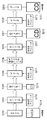
図16は、本発明の一実施形態における200パーセント拡大コピー時の画像処理の概略を示すブロック図である。図16は、A4原稿を200パーセント拡大してA4用紙へ出力する例を示している。本実施形態では、スキャン時の光学変倍は行わずに、ディジタル変倍処理による拡大を行っている。A4サイズ原稿5214中、出力される灰色部分のみをスキャナ5201で読み取り、エンコーダ5202でJPEG圧縮後、入力画像5215は、符号メモリ5203に格納される。
【0103】
その後、200パーセント拡大処理を行うため、JPEG画像データ5215は、JPEGデコーダ5204で復号され、ディジタル変倍ユニット5205へ入力され、200パーセント拡大処理が行われる。拡大後のデータが再びエンコーダ5206へ入力され、JPEG圧縮されて符号メモリ5207へと格納される。そして、200パーセント拡大されたJPEG画像データ5216は、デコーダ5208を介して、プリンタ5209へ出力される。
【0104】
すなわち、本実施形態に係る画像入出力システム100は、画像データを入力するリーダー部200と、画像データを所定の符号化パラメータで符号化して符号化データを生成し、符号化データを復号化して復号画像データを生成する制御装置110と、復号画像データを出力するプリンタ部300とを備える。そして、符号化データをシステム内のメモリ等に格納し、プリンタ部300から出力される復号画像データの出力形式を指定し、指定された出力形式に基づいて、符号化パラメータを決定する。また、指定された出力形式に基づいて、メモリ等に格納された符号化データを変換し、変換された符号化データをシステム内のメモリ等に格納し、格納された符号化データを復号化する。
【0105】
また、本実施形態に係る画像入出力システムは、符号化データの変換に際して、メモリ等に格納された符号化データを復号化して一旦復号化データを生成し、その復号化データを出力形式に基づいて変換して、変換された復号化データを符号化して符号化データを生成することを特徴とする。
【0106】
次に、図16に示すブロック図内のエンコーダ、デコーダに入力される符号化パラメータについて説明する。ここで、システムのデフォルトの目標圧縮率は1/32とする。まず、エンコーダ5202に設定する符号化パラメータには、図14(b)の1/8圧縮の量子化テーブルを用いる。そして、スキャナからA4原稿5214の1/4サイズの領域(灰色部分)を等倍で読み込む。すなわち、メモリに取り込まれる画像サイズが、A4に対して面積比で1/4となる。従って、目標圧縮率が1/8の量子化テーブルを用いることで、必要となるメモリ容量をA4サイズで1/32圧縮した容量に収まるようにした。また、実際には1/8圧縮のため、通常の1/32圧縮による場合よりも画像劣化を低く抑えることができる。
【0107】
すなわち、本実施形態に係る画像入出力システム100では、出力形式に基づいて決定された圧縮率の量子化テーブルを用いて、画像データを圧縮符号化することを特徴とする。
【0108】
目標圧縮率1/8の量子化テーブルで圧縮されたJPEGデータを復号するための符号化パラメータ5211には、図14(b)の1/8圧縮の量子化テーブルを設定する。次に、200パーセント変倍後の画像が入力されるエンコーダ5206に設定する符号化パラメータ5212には、図14(a)の1/32圧縮の量子化テーブルを用いる。これは、拡大後の画像は、画素数(面積)でA4サイズと等しくなるため、システムデフォルトの1/32圧縮のパラメータを適用するためである。同様に、符号化パラメータ5213には、1/32圧縮の量子化テーブルを用いる。
【0109】
すなわち、本実施形態に係る画像入出力システム100では、入力される画像データの拡大率と出力される画像データの出力サイズとを出力形式として指定し、リーダー部200が、出力サイズと拡大率に基づく画像データの所定領域のみを等倍率で入力し、制御装置110で拡大率に基づいて符号化パラメータを決定し、拡大率に基づいて符号化データを変換することを特徴とする。
【0110】
<その他の実施形態>
尚、本発明は、複数の機器(例えば、ホストコンピュータ、インタフェース機器、リーダ、プリンタ等)から構成されるシステムに適用しても、一つの機器からなる装置(例えば、複写機、ファクシミリ装置等)に適用してもよい。
【0111】
また、本発明の目的は、前述した実施形態の機能を実現するソフトウェアのプログラムコードを記録した記録媒体(または記憶媒体)を、システムあるいは装置に供給し、そのシステムあるいは装置のコンピュータ(またはCPUやMPU)が記録媒体に格納されたプログラムコードを読み出し実行することによっても、達成されることは言うまでもない。この場合、記録媒体から読み出されたプログラムコード自体が前述した実施形態の機能を実現することになり、そのプログラムコードを記録した記録媒体は本発明を構成することになる。また、コンピュータが読み出したプログラムコードを実行することにより、前述した実施形態の機能が実現されるだけでなく、そのプログラムコードの指示に基づき、コンピュータ上で稼働しているオペレーティングシステム(OS)などが実際の処理の一部または全部を行い、その処理によって前述した実施形態の機能が実現される場合も含まれることは言うまでもない。
【0112】
さらに、記録媒体から読み出されたプログラムコードが、コンピュータに挿入された機能拡張カードやコンピュータに接続された機能拡張ユニットに備わるメモリに書き込まれた後、そのプログラムコードの指示に基づき、その機能拡張カードや機能拡張ユニットに備わるCPUなどが実際の処理の一部または全部を行い、その処理によって前述した実施形態の機能が実現される場合も含まれることは言うまでもない。
【0113】
本発明を上記記録媒体に適用する場合、その記録媒体には、先に説明したフローチャートに対応するプログラムコードが格納されることになる。
【0114】
【発明の効果】
以上説明したように、本発明によれば、装置に搭載されているメモリ等を効率的に利用することにより、圧縮画像データの符号量を制御して、ディジタル変倍処理や解像度変換処理と画像圧縮で生じる画質の劣化を抑えることができる。
【図面の簡単な説明】
【図1】本発明の一実施形態に係る画像入出力システム全体の概略構成を示すブロック図である。
【図2】同実施形態における画像入出力システム100内のリーダー部200及びプリンタ部300の概観図である。
【図3】本発明の一実施形態における制御装置110の詳細な構成を示すブロック図である。
【図4】本発明の一実施形態におけるリーダー画像処理回路部222の詳細な構成を示すブロック図である。
【図5】制御部110内のスキャナI/F140におけるACSカウント部603の詳細な構成を示すブロック図である。
【図6】制御部110内のスキャナI/F140における画像処理機能を担う部分の詳細な構成を示すブロック図である。
【図7】制御部110内のプリンタI/F145における画像処理機能を担う部分の詳細な構成を示すブロック図である。
【図8】制御部110内のグラフィックプロセッサ135の詳細な構成を示すブロック図である。
【図9】グラフィックプロセッサ135内の画像回転部801で転送される画像データを説明するための図である。
【図10】グラフィックプロセッサ135内の画像回転部801における画像データの回転を説明するための図である。
【図11】本発明の一実施形態における画像入出力システム100でのPDL画像出力の手順を説明するためのフローチャートである。
【図12】本発明の一実施形態に係る画像入出力システム100におけるコピー画像出力の手順を説明するためのフローチャートである。
【図13】等倍(100パーセント)コピー時の画像処理の概略を示すブロック図である。
【図14】本発明の一実施形態に係るJPEG量子化テーブルの一例を示す図である。
【図15】本発明の一実施形態における200パーセント拡大コピー時の画像処理の概略を示すブロック図である。
【図16】本発明の一実施形態における200パーセント拡大コピー時の画像処理の概略を示すブロック図である。
【符号の説明】
100 画像入出力システム
110 制御装置
150 操作部
200 リーダー部
210 スキャナユニット
250 原稿給紙ユニット
300 プリンタ部
310 マーキングユニット
360 給紙ユニット
370 排紙ユニット[0001]
TECHNICAL FIELD OF THE INVENTION
The present invention relates to an image processing method for compressing and expanding image data.
[0002]
[Prior art]
Conventionally, when handling color image data, the size of the data amount has been a problem. For example, for a binary image sufficient to represent a black-and-white image, a standard color image consisting of 8 bits each for RGB requires 24 times the data amount to represent an image of the same size. I will. Therefore, when storing image data in a storage device such as a hard disk or a memory, storing the same number of color image data requires a storage capacity that is 24 times that of a monochrome image.
[0003]
That is, simply handling a color image requires 24 times the memory capacity and hard disk capacity of handling a black and white image, which leads to a large increase in cost. Therefore, conventionally, a method has been employed in which compression processing is performed on image data to reduce the data capacity, thereby reducing the storage capacity required for a memory and a hard disk mounted on a device or the like, and suppressing an increase in cost.
[0004]
[Problems to be solved by the invention]
However, when an irreversible compression method such as JPEG is used in the compression processing of image data, there is a problem that image quality is deteriorated due to compression, and the image deterioration is remarkable while increasing the compression ratio. Also, when digital scaling processing is performed to perform image data enlargement / reduction processing, image deterioration due to data complementation errors occurs. Therefore, when irreversible compression is further performed on digitally scaled image data, there is a problem that the image quality is particularly greatly deteriorated as compared with the original image data.
[0005]
The present invention has been made in view of such circumstances, and controls the code amount of compressed image data to suppress the deterioration in image quality caused by digital scaling processing, resolution conversion processing, and image compression processing. It is an object of the present invention to provide an image processing method capable of performing the above.
[0006]
[Means for Solving the Problems]
In order to solve this problem, the present invention is characterized by the following configuration according to an embodiment described later.
[0007]
[Invention 1] Input means for inputting image data;
Encoding means for encoding the image data with a predetermined encoding parameter to generate encoded data;
Decoding means for decoding the encoded data to generate decoded image data;
Output means for outputting the decoded image data;
An image processing method for an image processing apparatus comprising:
A first storing step of storing the encoded data in a first storing unit;
A designation step of designating an output format of the decoded image data output from the output means;
An encoding parameter determining step of determining the encoding parameter based on the output format specified by the specifying step,
A conversion step of converting the encoded data stored in the first storage means based on the output format specified by the specification step;
A second storage step of storing the encoded data converted in the conversion step in a second storage unit;
A decoding step of decoding the encoded data stored in the second storage means;
An image processing method comprising:
[0008]
[Invention 2] The conversion step comprises:
A second decoding step of decoding the encoded data stored in the first storage means to generate second decoded data;
A second conversion step of converting the second decoded data decoded in the second decoding step based on the output format;
A second encoding step of encoding the second decoded data converted in the second conversion step to generate encoded data;
The image processing method according to the first aspect, comprising:
[0009]
[Invention 3] The
[0010]
[Invention 4] The encoding parameter determining step determines the encoding parameter based on a ratio of a magnification or a resolution between the decoded image data output from the output unit and the image data input from the input unit. 4. The image processing method according to any one of
[0011]
[Invention 5] The specifying step determines an image area of the image data input from the input means, based on the output format of the decoded image data output from the output means,
An input control step of inputting only a predetermined area determined by the specifying step from the image data to the input unit;
The image processing method according to any one of
[0012]
[Invention 6] The invention, further comprising an encoding control step of causing the encoding means to compress and encode the image data using a quantization table of a compression rate determined based on the output format. 6. The image processing method according to any one of 1 to 5.
[0013]
[Invention 7] The specifying step specifies an enlargement ratio of the image data and an output size of the decoded image data as an output format,
The input control step allows only the area of the image data based on the output size and the enlargement ratio to be input to the input unit at an equal magnification,
The encoding parameter determining step determines the encoding parameter based on the enlargement ratio,
The converting step converts the encoded data based on the enlargement ratio.
The image processing method according to the first aspect of the present invention.
[0014]
[Invention 8] Input means for inputting image data;
Encoding means for encoding the image data with a predetermined encoding parameter to generate encoded data;
Decoding means for decoding the encoded data to generate decoded image data;
Output means for outputting the decoded image data;
An image processing apparatus comprising:
First storage means for storing the encoded data;
Specifying means for specifying an output format of the decoded image data output from the output means;
An encoding parameter determining unit that determines the encoding parameter based on the output format specified by the specifying unit;
Conversion means for converting the encoded data stored in the first storage means, based on the output format specified by the specification means;
Second storage means for storing the encoded data converted by the conversion means;
Further comprising
The decoding means decodes the encoded data stored in the second storage means
An image processing apparatus comprising:
[0015]
[Invention 9] The conversion unit includes:
A second decoding unit that decodes the encoded data stored in the first storage unit to generate second decoded data;
Second conversion means for converting the second decoded data decoded by the second decoding means based on the output format;
A second encoding unit that encodes the second decoded data converted by the second conversion unit to generate encoded data;
The image processing apparatus according to the eighth aspect, comprising:
[0016]
[Invention 10] The invention according to
[0017]
[Invention 11] The encoding parameter determining unit determines the encoding parameter based on a ratio of a magnification or a resolution between the decoded image data output from the output unit and the image data input from the input unit. The image processing apparatus according to any one of
[0018]
[Invention 12] The specifying unit determines an image area of the image data input from the input unit based on the output format of the decoded image data output from the output unit,
The input unit inputs only the image area determined by the specifying unit out of the image data;
The image processing apparatus according to any one of
[0019]
[Invention 13] The invention according to any one of
[0020]
[Invention 14] The specifying means specifies an enlargement ratio of the image data and an output size of the decoded image data as an output format,
The input unit inputs only a predetermined area of the image data based on the output size and the enlargement ratio at an equal magnification,
The encoding parameter determining means determines the encoding parameter based on the enlargement ratio,
The conversion unit converts encoded data based on the enlargement ratio.
An image processing apparatus according to an eighth aspect of the present invention.
[0021]
[Invention 15] Input means for inputting image data,
Encoding means for encoding the image data with a predetermined encoding parameter to generate encoded data;
Decoding means for decoding the encoded data to generate decoded image data;
Output means for outputting the decoded image data;
Computer with
A first storage procedure for storing the encoded data in first storage means;
A specifying procedure for specifying an output format of the decoded image data output from the output unit;
Based on the output format specified by the specifying procedure, an encoding parameter determining step of determining the encoding parameter,
A conversion step of converting the encoded data stored in the first storage unit based on the output format specified by the specification step;
A second storage procedure for storing the coded data converted in the conversion procedure in a second storage unit;
A decoding procedure for decoding the encoded data stored in the second storage means;
The program to execute.
[0022]
[Invention 16] A computer-readable recording medium storing the program according to
[0023]
The reason for the configuration of the present invention will be apparent from the following description.
[0024]
BEST MODE FOR CARRYING OUT THE INVENTION
Hereinafter, an image input / output system according to an embodiment of the present invention will be described with reference to the drawings.
[0025]
<Explanation of the whole image input / output system>
FIG. 1 is a block diagram showing a schematic configuration of an entire image input / output system according to an embodiment of the present invention. As shown in FIG. 1, in the image input /
[0026]
Further, the printer unit (image output device) 300 conveys the recording paper, prints image data thereon as a visible image, and discharges the recording paper outside the apparatus. The
[0027]
The
[0028]
The
[0029]
FIG. 2 is a schematic view of the
[0030]
[0031]
[0032]
A
[0033]
Paper fed from one of the
[0034]
When double-sided printing is set, the recording paper is conveyed to the
[0035]
<Description of Reader
FIG. 4 is a block diagram illustrating a detailed configuration of the reader image
[0036]
When the electric signal (analog image signal) is input to the reader image
[0037]
<Description of
FIG. 3 is a block diagram illustrating a detailed configuration of the
[0038]
The
[0039]
The
[0040]
The
[0041]
The
[0042]
A network controller (Network Controller) 121 is connected to the
[0043]
An
[0044]
The I /
[0045]
The panel I /
[0046]
The
[0047]
The real-
[0048]
The
[0049]
The scanner I /
[0050]
The printer I /
[0051]
The transfer of the raster image data developed on the
[0052]
<Description of Image Processing Function of Scanner I / F>
Here, a detailed description will be given of a portion that performs an image processing function in the scanner I /
[0053]
The digital signal whose read position timing has been corrected corrects the spectral characteristics of the
[0054]
<Description of ACS counting section 603>
FIG. 5 is a block diagram illustrating a detailed configuration of the ACS counting unit 603 in the scanner I /
[0055]
As described above, even in a black-and-white image, since there are a large number of color pixels when viewed microscopically, it is necessary to determine whether or not the pixel is really a color pixel based on information on color pixels around the target pixel. The
First Out: First Out First Out).
[0056]
[0057]
The
[0058]
In the
[0059]
<Description of Image Processing Function of Printer I /
FIG. 7 is a block diagram illustrating a detailed configuration of a part that performs an image processing function in the printer I /
[0060]
An image signal sent from the
[0061]
<Description of
FIG. 8 is a block diagram showing a detailed configuration of the
[0062]
The
[0063]
<Description of
Next, processing in the
[0064]
FIG. 9 is a diagram for explaining image data transferred by the
[0065]
As described above, in order to obtain an image of 32 pixels × 32 lines, it is necessary to perform the above unit data transfer 32 × 32 times, and it is necessary to transfer image data from discontinuous addresses.
[0066]
The image data transferred by the discontinuous addressing is written to the
[0067]
After the image rotation of 32 pixels × 32 lines (writing to the SRAM 136) is completed, the
[0068]
The
[0069]
<Description of the
Next, a processing procedure in the
[0070]
The
[0071]
<Description of Color
Next, a processing procedure in the color
[0072]
After performing the necessary settings, the
[0073]
The color
[0074]
(Equation 1)
In the above equation, R, G, B are inputs, X, Y, Z are outputs, a11, a12, a13, a21, a22, a23, a31, a32, a33, b1, b2, b3, c1, c2, c3 are Each is a coefficient.
[0076]
Various color space conversions, such as conversion from the RGB color space to the Yuv color space, can be performed by the above equation.
[0077]
Next, conversion by the
[0078]
<Description of
Next, a processing procedure in the
[0079]
The
[0080]
After that, the
[0081]
<Description of sequence when outputting PDL image>
FIG. 11 is a flowchart illustrating a procedure of outputting a PDL image in the image input /
[0082]
Next, a print instruction is given on the
[0083]
Further, the
[0084]
In step S114, the
[0085]
Next, the
For example, if the paper size specified by the print setting parameters is A4, but the
[0086]
In step S116, the
[0087]
Next, the
[0088]
Then, the
[0089]
<Sequence when outputting a copy image>
FIG. 12 is a flowchart illustrating a procedure of outputting a copy image in the image input /
[0090]
Next, when a copy start instruction is given on the
[0091]
In the conventional copier, the magnification in the sub-scanning direction is realized by changing the moving speed of the
[0092]
Next, the
[0093]
Further, the
[0094]
In step S125, the
[0095]
Further, the
[0096]
Then, the
[0097]
<Explanation of determination of reading area and selection of encoding parameter according to magnification ratio>
FIG. 13 is a block diagram showing an outline of image processing at the time of copying at the same size (100%). Image data obtained by reading an A4 size original 5108 by the
[0098]
Next, the
[0099]
FIG. 15 is a diagram illustrating a relationship between a manuscript of 200% enlarged copy and a copy output according to an embodiment of the present invention. A
[0100]
That is, in the image input /
[0101]
In the
[0102]
FIG. 16 is a block diagram illustrating an outline of image processing at the time of 200% enlarged copy according to an embodiment of the present invention. FIG. 16 shows an example in which an A4 document is enlarged by 200% and output on A4 paper. In the present embodiment, enlargement is performed by digital scaling without performing optical scaling during scanning. In the
[0103]
Thereafter, in order to perform the 200% enlargement processing, the
[0104]
That is, the image input /
[0105]
Further, when converting the encoded data, the image input / output system according to the present embodiment decodes the encoded data stored in the memory or the like to temporarily generate the decoded data, and converts the decoded data based on the output format. And converting the decoded data to generate encoded data.
[0106]
Next, encoding parameters input to the encoder and decoder in the block diagram shown in FIG. 16 will be described. Here, the default target compression ratio of the system is 1/32. First, a quantization table of 1/8 compression shown in FIG. 14B is used as an encoding parameter set in the
[0107]
That is, the image input /
[0108]
As the
[0109]
That is, in the image input /
[0110]
<Other embodiments>
Note that the present invention is applied to a system including a plurality of devices (for example, a host computer, an interface device, a reader, a printer, etc.), but a device including one device (for example, a copying machine, a facsimile machine, etc.). May be applied.
[0111]
Further, an object of the present invention is to supply a recording medium (or a storage medium) recording a program code of software for realizing the functions of the above-described embodiments to a system or an apparatus, and to provide a computer (or a CPU or a CPU) of the system or the apparatus. Needless to say, the present invention can also be achieved by the MPU) reading and executing the program code stored in the recording medium. In this case, the program code itself read from the recording medium implements the functions of the above-described embodiment, and the recording medium on which the program code is recorded constitutes the present invention. When the computer executes the readout program code, not only the functions of the above-described embodiments are realized, but also an operating system (OS) running on the computer based on the instruction of the program code. It goes without saying that a part or all of the actual processing is performed and the functions of the above-described embodiments are realized by the processing.
[0112]
Further, after the program code read from the recording medium is written into a memory provided in a function expansion card inserted into the computer or a function expansion unit connected to the computer, the function expansion is performed based on the instruction of the program code. It goes without saying that the CPU or the like provided in the card or the function expansion unit performs part or all of the actual processing, and the processing realizes the functions of the above-described embodiments.
[0113]
When the present invention is applied to the recording medium, the recording medium stores program codes corresponding to the flowcharts described above.
[0114]
【The invention's effect】
As described above, according to the present invention, the code amount of compressed image data is controlled by efficiently using a memory or the like mounted on the device, and digital scaling processing and resolution conversion processing are performed. Deterioration of image quality caused by compression can be suppressed.
[Brief description of the drawings]
FIG. 1 is a block diagram illustrating a schematic configuration of an entire image input / output system according to an embodiment of the present invention.
FIG. 2 is a schematic view of a
FIG. 3 is a block diagram illustrating a detailed configuration of a
FIG. 4 is a block diagram illustrating a detailed configuration of a reader image
FIG. 5 is a block diagram showing a detailed configuration of an ACS counting unit 603 in the scanner I /
FIG. 6 is a block diagram showing a detailed configuration of a portion having an image processing function in a scanner I /
FIG. 7 is a block diagram illustrating a detailed configuration of a part that performs an image processing function in a printer I /
FIG. 8 is a block diagram showing a detailed configuration of a
FIG. 9 is a diagram for describing image data transferred by an
FIG. 10 is a diagram for explaining rotation of image data in an
FIG. 11 is a flowchart illustrating a procedure of outputting a PDL image in the image input /
FIG. 12 is a flowchart illustrating a procedure of outputting a copy image in the image input /
FIG. 13 is a block diagram illustrating an outline of image processing during 1: 1 (100%) copy.
FIG. 14 is a diagram illustrating an example of a JPEG quantization table according to an embodiment of the present invention.
FIG. 15 is a block diagram illustrating an outline of image processing at the time of 200% enlarged copy according to an embodiment of the present invention.
FIG. 16 is a block diagram illustrating an outline of image processing at the time of 200% enlarged copy according to an embodiment of the present invention.
[Explanation of symbols]
100 image input / output system
110 control device
150 Operation unit
200 Leader Club
210 Scanner unit
250 Document feeding unit
300 Printer section
310 Marking unit
360 paper feed unit
370 paper ejection unit
Claims (1)
前記画像データを所定の符号化パラメータで符号化して符号化データを生成する符号化手段と、
前記符号化データを復号化して復号画像データを生成する復号化手段と、
前記復号画像データを出力する出力手段と
を備える画像処理装置の画像処理方法であって、
前記符号化データを第1の格納手段に格納する第1の格納工程と、
前記出力手段から出力される前記復号画像データの出力形式を指定する指定工程と、
前記指定工程によって指定された前記出力形式に基づいて、前記符号化パラメータを決定する符号化パラメータ決定工程と、
前記指定工程によって指定された前記出力形式に基づいて、前記第1の格納手段に格納された前記符号化データを変換する変換工程と、
前記変換工程で変換された符号化データを第2の格納手段に格納する第2の格納工程と、
前記第2の格納手段に格納された前記符号化データを復号化する復号化工程と
を有することを特徴とする画像処理方法。Input means for inputting image data;
Encoding means for encoding the image data with a predetermined encoding parameter to generate encoded data;
Decoding means for decoding the encoded data to generate decoded image data;
Output means for outputting the decoded image data, the image processing method of an image processing apparatus comprising:
A first storing step of storing the encoded data in a first storing unit;
A designation step of designating an output format of the decoded image data output from the output means;
An encoding parameter determining step of determining the encoding parameter based on the output format specified by the specifying step,
A conversion step of converting the encoded data stored in the first storage means based on the output format specified by the specification step;
A second storage step of storing the encoded data converted in the conversion step in a second storage unit;
A decoding step of decoding the encoded data stored in the second storage means.
Priority Applications (1)
| Application Number | Priority Date | Filing Date | Title |
|---|---|---|---|
| JP2002288877A JP2004128808A (en) | 2002-10-01 | 2002-10-01 | Method and apparatus for image processing |
Applications Claiming Priority (1)
| Application Number | Priority Date | Filing Date | Title |
|---|---|---|---|
| JP2002288877A JP2004128808A (en) | 2002-10-01 | 2002-10-01 | Method and apparatus for image processing |
Publications (1)
| Publication Number | Publication Date |
|---|---|
| JP2004128808A true JP2004128808A (en) | 2004-04-22 |
Family
ID=32281251
Family Applications (1)
| Application Number | Title | Priority Date | Filing Date |
|---|---|---|---|
| JP2002288877A Pending JP2004128808A (en) | 2002-10-01 | 2002-10-01 | Method and apparatus for image processing |
Country Status (1)
| Country | Link |
|---|---|
| JP (1) | JP2004128808A (en) |
-
2002
- 2002-10-01 JP JP2002288877A patent/JP2004128808A/en active Pending
Similar Documents
| Publication | Publication Date | Title |
|---|---|---|
| JP2004074561A (en) | Color image processing apparatus and image outputting method | |
| JP4498174B2 (en) | Image area information generating apparatus, image area information generating method, and program | |
| JP2004080601A (en) | Device, system, and method for processing image and control program | |
| JP2004153638A (en) | Copying apparatus | |
| US7920288B2 (en) | Image forming apparatus, image forming method and program | |
| JP2007106079A (en) | Image output device | |
| JP2004094731A (en) | Image forming apparatus and its method | |
| JP2007166516A (en) | Operation display for multi-function system | |
| JP2005111852A (en) | Imaging device, printing control method and program | |
| JP2004153568A (en) | Image forming device | |
| JP2004153567A (en) | Image input/output device and control method therefor, image input/output system and control program | |
| JP2005027037A (en) | Format conversion method and image processing apparatus | |
| JP2004128808A (en) | Method and apparatus for image processing | |
| JP2006224595A (en) | Printing system | |
| JP2004349858A (en) | Image processor and document duplicating apparatus using the same | |
| JP2008022082A (en) | Image forming apparatus and control method thereof | |
| JP2003023537A (en) | Image processor | |
| JP2008017121A (en) | Image input and output device | |
| JP2005277538A (en) | Image processing apparatus, program, and storage medium | |
| JP3970148B2 (en) | Image processing apparatus, image processing method, and program | |
| JP2007108942A (en) | Image processor | |
| JP2004214957A (en) | Image input/output device | |
| JP2007096695A (en) | Method and device for image processing, and computer program | |
| JP2009065351A (en) | Image processor, storage medium, and program | |
| JP2008153763A (en) | Image processor, storage medium, and program |
Legal Events
| Date | Code | Title | Description |
|---|---|---|---|
| A977 | Report on retrieval |
Free format text: JAPANESE INTERMEDIATE CODE: A971007 Effective date: 20060201 |
|
| A131 | Notification of reasons for refusal |
Free format text: JAPANESE INTERMEDIATE CODE: A131 Effective date: 20060206 |
|
| A02 | Decision of refusal |
Free format text: JAPANESE INTERMEDIATE CODE: A02 Effective date: 20060605 |