JP2004128793A - Network phone system and program - Google Patents
Network phone system and program Download PDFInfo
- Publication number
- JP2004128793A JP2004128793A JP2002288609A JP2002288609A JP2004128793A JP 2004128793 A JP2004128793 A JP 2004128793A JP 2002288609 A JP2002288609 A JP 2002288609A JP 2002288609 A JP2002288609 A JP 2002288609A JP 2004128793 A JP2004128793 A JP 2004128793A
- Authority
- JP
- Japan
- Prior art keywords
- telephone
- network
- telephone directory
- address
- terminal
- Prior art date
- Legal status (The legal status is an assumption and is not a legal conclusion. Google has not performed a legal analysis and makes no representation as to the accuracy of the status listed.)
- Granted
Links
Images


Abstract
Description
【0001】
【発明の属する技術分野】
この発明は、入力された音声情報をパケット変換してネットワーク上に送信する複数台の電話端末を備えたネットワーク電話システムおよびプログラムに関する。
【0002】
【従来の技術】
近年、入力された音声情報をパケット変換してインターネット上に送信するVoIP端末(インターネット電話端末)が普及し始めているが、従来においては、インターネット上に接続された電話端末に対して動的にそのIP(インターネット・プロトコル)アドレスを割当てる為のDHCP(ダイナミック・ホスト・コンフィグレーション・プロトコル:動的ホスト構成プロトコル)対応のインターネット電話システムが知られている(特許文献1参照)。
【0003】
【特許文献1】
特開2001−203806号公報
【0004】
ところで、システム内をグループ分けした複数のサブネット(ローカルネット)のうち、何れかのサブネットへ任意に移動可能なノート型あるいはモバイル型のVoIP端末にあっては、それが接続されている普段の設置場所のサブネットから他の場所のサブネットへ移動することがある為、その端末の位置情報を管理するようにしている。
この場合、RFC(Request for Comments)2543で定義されているように、VoIP端末のアドレスやそれが接続されている場所の位置情報の管理は、VoIP用のサーバであるSIP(Session Initiation Protocol:セッション開始プロトコル)サーバによって行われている。
【0005】
図19は、一般的なSIPサーバを概略的に説明する為の図である。
SIPサーバ100は、システム内をグループ分けした各サブネット毎に配置されているもので、後述するレジスタ機能、プロキシ機能、リダイレクト機能を有する構成となっている。
なお、図中、▲1▼〜▲7▼は、動作の流れを示した動作手順であり、▲1▼および▲2▼(登録)は、非同期で実行され、▲3▼(発呼)の実行前に完了し、それ以降の▲3▼(発呼)、▲4▼(問い合わせ)、▲5▼(発呼)、▲6▼および▲7▼(応答)の動作は、連続して実行されることを示している。
【0006】
このSIPサーバ100内のレジスタ機能は、各VoIP端末101、102から送信されて来た登録要求を受け付けると、端末毎にその仮想的SIPアドレスと実SIPアドレスとの対応関係をロケーション・サーバ103に対して登録する為の機能である。なお、仮想的SIPアドレス、実SIPアドレスは、各VoIP端末101、102が移動する可能性があることを考慮して端末毎に割当てられたアドレスであり、実際の移動先のアドレスは、実SIPアドレスによって示される。
【0007】
この状態において、発信側の端末101は、通話相手先の仮想的SIPアドレスを指定して発呼を行うと、SIPサーバ100内のプロキシ機能は、ロケーション・サーバ103に対して問い合わせを行い、通話相手先の仮想的SIPアドレスに対応付けられている実SIPアドレスを取得して、着信側の端末102に対して発呼し、その応答を発信側の端末101へ返信する為の機能である。
この場合、SIPサーバ100内のリダイレクト機能は、着信側の端末102が別のSIPサーバ100が管理している他のサブネット側に移動した場合に、発信側の端末101に対しては、移動先の実SIPアドレスを返信するようにしている。なお、SIPサーバ100とロケーション・サーバ103との間には、LDAP(Lightweight Directory Access Protocol:簡易・軽量化のディレクトリ・アクセス・プロトコル)が介在している。
【0008】
【発明が解決しようとする課題】
しかしながら、上述のように各VoIP端末101、102のアドレスや位置情報の管理は、サブネット毎に設けられているSIPサーバ100によって行うようにしているが、高価なSIPサーバ100を導入することは、初期導入コストが高額となると共に、運用コストも嵩む等の問題があった。
【0009】
この発明の課題は、音声情報をパケット変換してネットワーク上に送信する電話端末を利用して通話相手先を呼び出す場合、その相手先がどの場所(サブネット)に移動しても、SIP(Session Initiation Protocol:セッション開始プロトコル)サーバを導入せずに、各電話端末側に備えられている電話帳機能を活用して呼び出すことが可能なネットワーク電話システムを提供できるようにすることである。
【0010】
【課題を解決するための手段】
請求項1記載の発明は、入力された音声情報をパケット変換してネットワーク上に送信する複数台の電話端末を備えたネットワーク電話システムであって、前記電話端末は、複数のサブネットに対応して各電話端末毎に割当てられている全てのネットワーク用アドレスを相手先別に電話帳データとして記憶管理する電話帳記憶手段と、前記電話帳の中から通話相手先が選択指定された場合に、その通話相手先に対応付けられている前記電話帳データから全てのネットワーク用アドレスを順次読み出すアドレス読出手段と、このアドレス読出手段によって読み出された各ネットワーク用アドレスに基づいて前記通話相手先の電話端末を呼び出す発呼手段とを具備するものである。
更に、コンピュータに対して、上述した請求項1記載の発明に示した主要機能を実現させるためのプログラムを提供する(請求項7記載の発明)。
【0011】
したがって、請求項1、7記載の発明は、複数のサブネットに対応して各電話端末毎に割当てられている全てのネットワーク用アドレスを相手先別に電話帳データとして記憶管理している状態において、この電話帳の中から通話相手先が選択指定された場合に、その通話相手先に対応付けられている電話帳データから全てのネットワーク用アドレスを順次読み出して発呼するようにしたから、通話相手先がどの場所(サブネット)に移動していても、システム上の各サブネット毎に全ての端末呼び出しを行うことができ、確実に通話相手先を呼び出すことが可能となる。したがって、従来のようなSIPサーバを導入することなく、電話端末側に備えられている電話帳機能を活用するという簡単な手法によって実現可能となる為、システム全体が大幅に簡素化され、初期導入コストや運用コストの低減化も可能となる等、実用効果の高いネットワーク電話システムを提供することができる。
【0012】
なお、請求項1記載の発明は次のようなものであってもよい。
複数台の電話端末のうち、何れからの電話端末によって作成された電話帳データを他の各電話端末へ配信する配信手段と、この配信手段によって配信されて来た電話帳データを受信取得して自己の前記電話帳記憶手段内に登録する登録手段とを設けた(請求項2記載の発明)。
したがって、請求項2記載の発明によれば、請求項1記載の発明と同様の効果を有する他に、何れからの電話端末によって作成された電話帳データを他の各電話端末へ配信して登録するようにしたから、同一内容の電話帳データを個別に作成/編集する必要がなくなり、システム全体として電話帳データの作成作業を効率良く行うことが可能となる。
【0013】
前記電話帳データの中から各ネットワーク用アドレスを順次読み出す為の優先順位を前記電話帳記憶手段内に任意に設定する設定手段を設け、前記アドレス読出手段は、前記選択指定された通話相手先対応の各ネットワーク用アドレスを順次読み出す際に、この各アドレスに対応付けられている前記優先順位を参照することによって当該優先順位にしたがった順序で読み出す(請求項3記載の発明)。
したがって、請求項3記載の発明によれば、請求項1記載の発明と同様の効果を有する他に、通話相手先に対応付けられている各ネットワーク用アドレスを順次読み出す為の優先順位を任意に設定可能としたから、例えば、普段勤務している場所を最優先すると共に、日常的に移動する可能性の高い場所を次の優先場所とする等、各アドレスに対応して優先順位を設定しておけば、その順序にしたがって各アドレスを1つずつ読み出すことができ、通話相手先を迅速に呼び出すことが可能となる。
【0014】
前記設定手段は、各電話端末の移動先を時間帯別に記憶するスケジュール情報を参照することによって、現在の時間帯に該当する移動先を特定し、この移動先のサブネットに対応付けられているネットワーク用アドレスに対して高い優先順位を設定する(請求項4記載の発明)。
したがって、請求項4記載の発明によれば、請求項1記載の発明と同様の効果を有する他に、通話相手先を優先順位にしたがって呼び出す場合に、予め各電話端末の移動先を時間帯別に登録管理するスケジュール情報にしたがって優先順位を自動設定するようにしたから、優先順位を手作業で設定する必要はなく、また、相手先の行動を事前に知っておく必要もなく、システム全体としての効率アップが可能となる。
【0015】
前記電話帳記憶手段は、予め決められている複数のサブネットに対応して各電話端末毎に割当てられている全てのネットワーク用アドレスを相手先別に記憶管理する他、前記複数のサブネット以外のサブネットへの移動を考慮して、セッション開始プロトコル用のサーバアドレスを記憶管理し、前記アドレス読出手段は、電話帳の中から任意に選択指定された通話相手先に対応付けられている全てのネットワーク用アドレスを順次読み出した際に、その相手先を呼び出すことができなかった場合には、前記セッション開始プロトコル用のサーバアドレスを読み出すことにより、当該サーバを経由して発呼する(請求項5記載の発明)。
したがって、請求項5記載の発明によれば、請求項1記載の発明と同様の効果を有する他に、複数のサブネット以外のサブネットへの移動を考慮して、セッション開始プロトコル用のサーバアドレスを記憶管理し、電話帳の中から任意に選択指定された通話相手先に対応付けられている全てのネットワーク用アドレスを順次読み出した際に、その相手先を呼び出すことができなかった場合に、セッション開始プロトコル用のサーバアドレスを読み出すようにしたから、通話相手先が普段居る場所あるいは移動する可能性がある場所に対しては、SIPサーバを経由せずに呼び出すことができ、通話相手先が普段居ない場所に移動した場合でも、通常のSIPサーバを経由することによりその通話相手先を呼び出すことができ、システム全体としての柔軟性を増大させることが可能となる。
【0016】
各電話端末毎に、現在使用している使用ユーザ名を一時保存するユーザ名保存手段を設け、各電話端末毎に設けられている前記電話帳記憶手段は、複数のサブネットに対応して各電話端末毎に割当てられている全てのネットワーク用アドレスを相手先別に記憶管理する他、そのユーザ名も合わせて記憶管理し、発信側の電話端末において、前記アドレス読出手段は、電話帳の中から任意に選択指定された通話相手先に対応付けられている全てのネットワーク用アドレスを順次読み出す際に、この電話帳内に登録されているユーザ名を読み出し、前記発呼手段は、前記読み出された各ネットワーク用アドレスにユーザ名を結合して相手先の電話端末を呼び出し、着信側の電話端末は、前記ユーザ名保存手段内に一時保存されている現在使用のユーザ名と、発信側の電話端末からネットワーク用アドレスに結合して送信されて来たユーザ名とを比較し、両者が異なる場合にはエラー応答を行う(請求項6記載の発明)。
したがって、請求項6記載の発明によれば、請求項1記載の発明と同様の効果を有する他に、各電話端末毎に、現在使用している使用ユーザ名を一時保存すると共に、電話帳内に相手先別にそのユーザ名を記憶管理している状態において、発信側の電話端末は、電話帳の中から任意に選択指定された通話相手先に対応付けられている全てのネットワーク用アドレスを順次読み出す際に、この電話帳内のユーザ名とネットワーク用アドレスとを結合して発呼し、着信側の電話端末は、一時保存されている現在使用のユーザ名と、発信側の電話端末からネットワーク用アドレスに結合して送信されて来たユーザ名とを比較し、両者が異なる場合にはエラー応答を行うようにしたから、1台の電話端末を複数のユーザが共有して使用可能としている場合でも、所望のユーザを通話相手先として確実に呼び出すことができる。
【0017】
【発明の実施の形態】
(第1実施形態)
以下、図1〜図6を参照してこの発明の第1実施形態を説明する。
図1は、この実施形態におけるネットワーク電話システムの全体構成を示したブロック図である。
このネットワーク電話システムは、無線LANシステムであり、このシステム全体として複数(この実施形態においては2つ)のサブネット(ローカルネット)▲1▼、▲2▼に区分されており、複数台のVoIP端末1のうち、VoIP端末「A」、「B」は、サブネット▲1▼側に接続され、VoIP端末「C」、「D」は、サブネット▲2▼側に接続されている。なお、説明の簡素化を図る為に、図1では、サブネット数を“2”、VoIP端末1の台数を“4”とした場合を例示している。
【0018】
各VoIP端末1は、インターネット電話ソフト等がインストールされ、音声情報をパケット変換してインターネット上に送信するノート型、モバイル型のパーソナルコンピュータ等であり、インターネットの標準プロトコルであるTCP/IPプロトコルを使用して通話相手先を呼び出すようにしている為、発呼時には、通話相手先のIPアドレスを入力指定する。なお、この実施形態では、ネットワークとしてインターネットを例に説明しているが、ネットワークの形態はインターネットに限定されるものではなく、その他のネットワークシステムに広く適用できることは勿論である。
DHCP(ダイナミック・ホスト・コンフィグレーション・プロトコル:動的ホスト構成プロトコル)サーバ2は、各VoIP端末1に対して動的にIPアドレスを割当てるもので、この実施形態においては、一台のDHCPサーバ2によって各サブネット▲1▼、▲2▼側のVoIP端末1に対してIPアドレスを割当てるようにしている。このDHCPサーバ2は、中継動作を行うルータ3に接続されていると共に、アクセスポイント4を含む無線LANを介して各VoIP端末1に接続されている。
【0019】
図2は、DHCPサーバ2側で管理している各VoIP端末1の接続場所と、その場所に対応して各端末に割当てられたIPアドレスとの関係を示した図である。この場合、DHCPサーバ2側では、VoIP端末1毎に、そのMACアドレス(ハードウェアアドレス)の他、サブネット▲1▼、▲2▼に対応して各VoIP端末1にそれぞれ割当てたIPアドレスを記憶管理する。つまり、この実施形態においては、VoIP端末1毎に、全てのサブネットに対応してそのIPアドレスを記憶管理するようにしている。なお、IPアドレスを構成するデータのうち、図中、「128.1.1」は、サブネット▲1▼のアドレスを示し、「128.1.2」は、サブネット▲2▼のアドレスを示し、更に、サブネットアドレスに続く、「100」〜「103」は、対応するVoIP端末「A」〜「D」のアドレスを示している。
【0020】
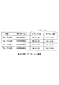
図3は、各VoIP端末1側で管理されている電話帳ファイル10の構成を示した図である。
各VoIP端末1に対応して設けられている電話帳ファイル10は、着信者名(相手先名)“A”〜“X”毎に、全てのサブネットに対応付けられているIPアドレス“1”〜“n”を記憶する構成となっている。つまり、着信者名別のIPアドレスは、サブネット数に相当する数だけ記憶されており、上述の例では、着信者名A〜D別に、サブネット▲1▼、▲2▼対応して2種類のIPアドレスが電話帳データとして記憶されている。なお、この第1実施形態において、個々の着信者名に対応付けられている複数のIPアドレスは、サブネット▲1▼、▲2▼の並び順となっている。
このように構成された電話帳ファイル10は、何れかのVoIP端末1によって作成されたものであり、その作成元のVoIP端末1が他の全てのVoIP端末1に対して電話帳データを配信すると、他の各VoIP端末1は、電話帳データを受信取得して自己の電話帳ファイル10内に登録するようにしている。
【0021】
また、各VoIP端末1は、所望のVoIP端末1を指定して通話を開始する際に、自己の電話帳ファイル10の内容を読み出して、その相手先名の一覧を表示出力させる。この状態において、相手先名一覧画面の中から所望の相手先が通話先として選択指定されると、VoIP端末1は、電話帳ファイル10をアクセスし、その通話相手先に対応付けられている電話帳レコードを読出対象として指定し、この指定レコード内に格納されている全てのIPアドレスを1つずつ順次読み出して、通話相手先であるVoIP端末1を順次呼び出すようにしている。これによって、各IPアドレスによって全てのサブネット▲1▼、▲2▼側の各VoIP端末1が呼び出されることになる。
【0022】
図4は、VoIP端末1の基本的構成要素を示したブロック図である。
CPU11は、記憶装置12内のオペレーティングシステムや各種アプリケーションソフトにしたがってこのVoIP端末1の全体動作を制御する中央演算処理装置である。記憶装置12は、プログラム記憶領域とデータ記憶領域とを有し、このプログラム記憶領域内には、オペレーティングシステムの他に、各種アプリケーションプログラム等が格納され、また、データ記憶領域には、上述した電話帳ファイル10等が格納され、磁気的、光学的、半導体メモリ等やその駆動系によって構成されている。
【0023】
この記録装置12はハードディスク等の固定的なメモリの他、CD−ROM、DVD等の着脱自在な記憶媒体を装着可能な構成であってもよい。この記憶装置12内のプログラムやデータは、必要に応じてRAM(例えば、スタティックRAM)13にロードされたり、RAM13内のデータが記憶装置12にセーブされる。なお、RAM13内には、プログラム実行領域と作業領域とを有している。
更に、CPU11は無線LAN装置14を介して他の電子機器側のプログラム/データを直接アクセスして使用したり、無線LAN装置14を介してダウンロード受信することもできる。一方、CPU11にはその入出力周辺デバイスである入力装置15、表示装置16、マイクロホーン17、スピーカ18がバスラインを介して接続されており、入出力プログラムにしたがってCPU11はそれらの動作を制御する。
【0024】
次に、この第1実施形態におけるネットワーク電話システムの動作アルゴリズムを図5および図6に示すフローチャートを参照して説明する。ここで、これらのフローチャートに記述されている各機能は、読み取り可能なプログラムコードの形態で格納されており、このプログラムコードにしたがった動作を逐次実行する。また、伝送媒体を介して伝送されてきた上述のプログラムコードにしたがった動作を逐次実行することもできる。このことは後述する他の実施形態においても同様であり、記録媒体の他、伝送媒体を介して外部供給されたプログラム/データを利用してこの実施形態特有の動作を実行することもできる。
【0025】
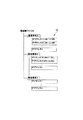
図5は、VoIP端末1側が実行する電話帳データ作成登録処理を示したフローチャートである。
先ず、VoIP端末1は、作業メニュー画面の中から「新規作成/編集」のメニュー項目が選択指定されると(ステップA1)、電話帳作成/編集画面を表示すると共に、この画面内に電話帳データが入力されると、入力データに基づいて電話帳データを作成/編集する(ステップA2)。ここで、作成/編集の終了が指示されると、この電話帳データを自己の電話帳ファイル10内に新規保存/上書き保存する(ステップA3)。
【0026】
ここで、電話帳データの作成/編集元であるVoIP端末1において、作業メニュー画面の中から「送信」のメニュー項目が選択指定されると(ステップA1)、電話帳ファイル10を読み出し、この電話帳ファイル10をメールの添付ファイルとして、他の全てのVoIP端末1へメール送信する(ステップA4)。
いま、電話帳データの作成/編集元であるVoIP端末1からメールを受信した他の全てのVoIP端末1は(ステップA5)、そのメールから添付ファイル(電話帳データ)を受信取得し(ステップA6)、自己の電話帳ファイル10内に新規保存/上書き保存する(ステップA3)。
【0027】
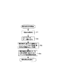
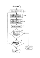
図6は、各VoIP端末1側が実行する通話呼び出し処理(ダイヤル処理)を示したフローチャートである。
先ず、VoIP端末1は、自己の電話帳ファイル10をアクセスして各着信者名(相手先名)を読み出し、相手先名の一覧画面を表示させる(ステップB1)。この相手先一覧画面の中から所望の通話相手先が選択指定されると(ステップB2)、選択相手対応の電話帳レコードを読出対象として指定する(ステップB3)。この状態において、指定レコード内の各IPアドレスのうち、その1つをその並び順にしたがって読み出し(ステップB4)、このIPアドレス宛てにRFC(Request for Comments)3261にしたがって発呼する(ステップB5)。そして、発呼後から所定時間を経過しても相手先からの応答が無ければ(ステップB6でYES)、タイムアウトと判断してステップB7に移り、選択相手対応の電話帳レコードから全てのIPアドレスを取得し終わったかを判別する。
【0028】
いま、先頭のIPアドレス(サブネット▲1▼対応のアドレス)を取得した場合であるからステップB4に戻り、選択相手対応の電話帳レコードから次のIPアドレス(サブネット▲2▼対応のアドレス)を取得し、以下、上述の発呼動作を繰り返す(ステップB4〜B7)。
この結果、全てのIPアドレスを取得して発呼動作を行っても、相手先から応答が無ければ(ステップB7でYES)、呼び出しエラーとしてダイヤル処理を終了するが、タイムアウト前に何れの相手先から応答が有れば(ステップB6でNO)、正常にダイヤル処理が完了したものとして終了する。
【0029】
以上のように、この第1実施形態においては、複数のサブネットに対応して各VoIP端末1毎に割当てられている全てのIPアドレスを相手先別に電話帳ファイル10内に記憶管理している状態において、発信側のVoIP端末1は、電話帳ファイル10の中から通話相手先が選択指定された場合に、その通話相手先に対応付けられている電話帳レコードから全てのIPアドレスを順次読み出して発呼するようにしたから、通話相手先がどの場所(サブネット)に移動していても、システム上の各サブネット毎に全ての端末呼び出しを行うことができ、確実に通話相手先を呼び出すことが可能となる。したがって、従来のようなSIPサーバを導入することなく、電話端末側に備えられている電話帳機能を活用するという簡単な手法によって実現可能となる為、システム全体が大幅に簡素化され、初期導入コストや運用コストの低減化も可能となる等、実用効果の高いネットワーク電話システムを提供することができる。
【0030】
また、複数台のVoIP端末1のうち、何れからのVoIP端末1によって新規作成/編集された電話帳データを他の全てのVoIP端末1へ配信すると、各VoIP端末1は、この電話帳データを受信取得して自己の電話帳ファイル10内に登録するようにしたから、同一内容の電話帳ファイル10を個別に作成/編集する必要がなくなり、システム全体として電話帳データの作成/編集作業を効率良く行うことが可能となる。
【0031】
なお、上述した第1実施形態においては、システム上に2つのサブネット▲1▼、▲2▼を構築した場合を例示したが、勿論、サブネット数は任意であり、3以上のサブネットを構築してもよい。この場合、上述した如く、電話帳ファイルにはサブネット数分のIPアドレスを相手先別に記憶管理すればよい。
また、複数のサブネットに共通使用されるDHCPサーバ2を設ける場合の他、サブネット毎にDHCPサーバ2を設けるようにしてもよい。
【0032】
(第2実施形態)
以下、この発明の第2実施形態について図7および図8を参照して説明する。なお、上述した第1実施形態は、通話相手先に対応付けられている全てのIPアドレスを電話帳レコードの中からその並び順にしたがって1つずつ順次読み出して、通話相手先のVoIP端末1を呼び出すようにしたが、この第2実施形態は、予め設定しておいた優先順位にしたがって全てのIPアドレスを電話帳レコードの中から1つずつ順次読み出して、通話相手先のVoIP端末1を呼び出すようにしたものである。
ここで、両実施形態において基本的に同一のものは、同一符号を付して示し、その説明を省略する他、以下、第2実施形態の特徴部分を中心に説明するものとする。
【0033】
図7は、この第2実施形態における電話帳ファイル10の構造を示した図である。
この電話帳ファイル10は、上述した第1実施形態と同様に、着信者名“A”〜“X”毎に、全てのサブネットに対応付けられているIPアドレス“1”〜“n”を記憶する他、この第2実施形態においては、着信者名別の各IPアドレスに対応してその読出順を示す「優先順位」を記憶する構成となっている。
この場合、電話帳データの新規作成/編集時に、その作成/編集画面には、優先順位を入力する新たな入力フィールドを設け、例えば、普段勤務している場所を最優先し、次に優先する場所として、移動する可能性が高い場所となるように、各IPアドレス対応の入力フィールドにその優先順位を入力するようにしている。
【0034】
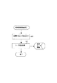
図8は、この第2実施形態において、各VoIP端末1側が実行する通話呼び出し処理(ダイヤル処理)を示したフローチャートである。
先ず、VoIP端末1は、自己の電話帳ファイル10をアクセスして相手先名の一覧画面を表示させた状態において(ステップC1)、この相手先一覧画面の中から所望の通話相手先が選択指定されると(ステップC1)、選択相手対応の電話帳レコードを読出対象として指定する(ステップC3)。そして、指定レコード内の各IPアドレスに対応付けられている「優先順位」を参照して、その読出順を決定する(ステップC4)。
以下、この「優先順位」で示される読出順にしたがって各IPアドレスを1つずつ読み出し(ステップC5)、上述した第1実施形態と同様の発呼動作を繰り返す(ステップC5〜C8)。
【0035】
以上のように、この第2実施形態においては、通話相手先に対応付けられている各IPアドレスを順次読み出す為の優先順位を任意に設定可能としたから、例えば、普段勤務している場所を最優先すると共に、日常的に移動する可能性の高い場所を次の優先場所とする等、各IPアドレスに対応して優先順位を設定しておけば、その順序にしたがって各IPアドレスを1つずつ読み出すことができ、通話相手先を迅速に呼び出すことが可能となる。
【0036】
なお、上述した第2実施形態においては、各IPアドレスの読出順を示す「優先順位」を設定する際に、電話帳データの新規作成/編集時において、その作成/編集画面内に「優先順位」を入力設定するようにしたが、この「優先順位」の設定を自動的に行うようにしてもよい。
図9および図10は、優先順位の自動設定を行う場合を例示したもので、図9は、各人の行動スケジュールを管理するスケジュールファイルSFを示した図である。
このスケジュールファイルSFは、スケジュールサーバ(図示せず)側に記憶管理されているもので、各VoIP端末1に対応して時間帯別にどの場所に居るかを示す場所情報(サブネット)を記憶する構成となっている。例えば、VoIP端末「A」は、“9:00〜15:00”の間は、普段勤務している場所(サブネット▲1▼)に居るが、“15:00以降”は、他の場所(サブネット▲2▼)に移動することを示している。
【0037】
図10は、スケジュールファイルSFを参照して優先順位の自動設定を行う場合におけるVoIP端末1の動作を示したフローチャートである。
先ず、VoIP端末1は、システム日時をアクセスして現在時刻を取得すると共に(ステップD1)、スケジュールファイルSFを取得する(ステップD2)。そして、現在時刻に基づいてスケジュールファイルSFをアクセスし、現在時刻に該当する時間帯の場所情報を読み出し、その場所に対応付けられているIPアドレスの優先順位を最優先として設定する(ステップD3)。いま、VoIP端末「A」において、現在時刻が“11:30”であれば、時間帯“9:00〜15:00”に該当し、普段勤務している場所(サブネット▲1▼)対応のIPアドレスの優先順位が最優先として設定される。そして、現在時刻を基準として、他の各時間帯に該当するIPアドレスの優先順位を時間の進行に応じて順次設定する(ステップD4)。この場合、VoIP端末「A」において、次の時間帯“15:00以降”は、サブネット▲2▼対応のIPアドレスの優先順位が次に高い優先順位として設定される。
【0038】
このようにスケジュールファイルSFを参照して優先順位の自動設定を行うようにすれば、優先順位を手作業で設定する必要はなく、また、相手先の行動を事前に知っておく必要もなく、システム全体としての効率アップが可能となる。
なお、スケジュールファイルSFの管理場所として、スケジュールサーバ(図示せず)としたが、勿論、VoIP端末1がスケジュールファイルSFを記憶管理するようにしてもよい。
【0039】
(第3実施形態)
以下、この発明の第3実施形態について図11〜図14を参照して説明する。なお、上述した第1実施形態は、VoIP端末1が移動する可能性があるサブネット▲1▼、▲2▼に適用した場合を示したが、この第3実施形態においては、通常移動することがない他の場所(サブネット▲3▼)にVoIP端末1が移動した場合にも対応可能とする為に、このサブネット▲3▼へのアクセスは、SIP(Session Initiation Protocol:セッション開始プロトコル)サーバを経由して行うようにしたものである。
ここで、両実施形態において基本的に同一のものは、同一符号を付して示し、その説明は省略するものとする。
【0040】
図11は、この第3実施形態におけるネットワーク電話システムを示したブロック図である。
このネットワーク電話システムには、サブネット▲1▼側のVoIP端末「A」、「B」と、サブネット▲2▼側のVoIP端末「C」、「D」の他に、サブネット▲3▼側のVoIP端末「E」、「F」が設けられている。そして、DHCPサーバ2は、ルータ3に接続されていると共に、アクセスポイント4を含む無線LANを介して各VoIP端末1に接続されている。また、SIPサーバ5は、ルータ3、無線LANを介してサブネット▲3▼側のVoIP端末「E」、「F」に接続されている。なお、DHCPサーバ2、SIPサーバ5は、DHCPサーバ機能、SIPサーバ機能を備えた1台のサーバ装置によって構成するようにしてもよい。
【0041】
図12は、この第3実施形態における電話帳ファイル10の構造を示した図である。
この電話帳ファイル10は、上述した第1実施形態と同様、着信者名別にサブネット▲1▼、▲2▼対応して2種類のIPアドレスを記憶する他、特に、この第3実施形態においては、SIPサーバ5経由での発呼を可能とする為、その「SIPアドレス」を追加記憶した構成となっている。
【0042】
図13は、VoIP端末1がSIPサーバ5側に対してアドレス登録を行う場合の登録処理を示したフローチャートである。
先ず、VoIP端末1は、自己のIPアドレスの中からサブネットのアドレスを取得し(ステップE1)、このアドレスに基づいて電話帳をアクセスし、普段自分が居る場所と比較する(ステップE2)。つまり、自己のIPアドレスの中から取得したサブネットアドレスが電話帳ファイル10内に登録されているか否かに基づいて普段自分が居る場所か否かを判別する。いま、サブネットアドレスが電話帳ファイル10内に登録されていれば、普段自分が居る場所であると判断し、この登録処理の終了となるが、電話帳ファイル10内に登録されていなければ、普段自分が居ない場所であると判断してステップE3に移り、RFC3261/3263にしたがってSIPサーバ5側に対してアドレス登録を行う。
【0043】
図14は、第3実施形態において、各VoIP端末1側が実行する通話呼び出し処理(ダイヤル処理)を示したフローチャートである。
先ず、VoIP端末1は、自己の電話帳ファイル10をアクセスして相手先名一覧画面を表示させた状態において、この相手先一覧画面の中から所望の通話相手先が選択指定されると(ステップF1)、選択相手対応の電話帳レコードを読出対象として指定する(ステップF2)。そして、上述した第2実施形態と同様に、指定レコード内の各IPアドレスに対応付けられている「優先順位」を参照して、その読出順を決定する(ステップF3)。
【0044】
以下、この「優先順位」で示される読出順にしたがって各IPアドレスを1つずつ読み出し、上述した第1実施形態と同様の発呼動作を繰り返す(ステップF4〜F7)。この結果、何れの相手先から応答が有れば(ステップF6でNO)、正常にダイヤル処理が完了したものとして終了するが、何れの相手先から応答が無ければ(ステップF6、F7でYES)次のステップF8に移り、選択相手対応の電話帳レコードから「SIPアドレス」を取得した後、RFC3261にしたがってSIPサーバ5経由で発呼する(ステップF9)。
【0045】
以上のように、この第3実施形態においては、普段居ない場所(サブネット▲3▼)に移動した時のみそのVoIP端末1がSIPサーバ5側に対してアドレス登録を行い、他のVoIP端末1は、サブネット▲3▼へ移動したVoIP端末1を呼び出す際に、上述の第1実施形態と同様、電話帳データからその通話相手先に対応付けられている各IPアドレスを順次読み出して発呼を試みるが、その通話相手が見つからなかった場合には、SIPサーバ5経由で発呼を行うようにしたから、通話相手先が普段居ない場所に移動した場合でも、その通話相手先を呼び出すことができ、システム全体としての柔軟性を増大させることが可能となる。
【0046】
なお、上述した第4実施形態においては、自己のIPアドレスの中から取得したサブネットアドレスが電話帳に登録されているか否かに基づいて普段自分が居る場所か否かを判別するようにしたが、その他の判定方法としては、現在使用しているアクセスポイントを識別し、このアクセスポイントに基づいて普段自分が使用しているアクセスポイントかを比較するようにしてもよい。
【0047】
(第4実施形態)
以下、この発明の第4実施形態について図15〜図18を参照して説明する。なお、上述した第1〜第3実施形態は、VoIP端末1を一人のユーザが専有使用する場合を想定したが、この第4実施形態においては、1台のVoIP端末1を複数ユーザで共用使用する場合に適用したものである。
ここで、両実施形態において基本的に同一のものは、同一符号を付して示し、その説明は省略するものとする。
【0048】
図15は、この第4実施形態における電話帳ファイル10の構造を示した図である。
この電話帳ファイル10は、上述した第1実施形態と同様、着信者名別に各サブネットに対応したIPアドレスを記憶するものであるが、特に、この第4実施形態においては、着信者名毎に「SIPユーザ名」を追加記憶する構成となっている。この例では、着信者「B」と「C」は、同じVoIP端末1を共用している場合を示し、着信者「B」、「C」に対応付けられている各IPアドレスは同一内容となっている。
【0049】
図16は、この第4実施形態の動作概要を説明する為の図である。
先ず、各VoIP端末1においては、その端末使用時に自己のユーザ名を一時保存するログイン処理を行う。
図17は、端末使用時に自己のユーザ名を一時保存するログイン処理を示したフローチャートであり、各VoIP端末1は、端末使用時に自己のユーザ名が入力されると(ステップG1)、このユーザ名をログインユーザとして一時保存する処理を行う(ステップG2)。
【0050】
いま、VoIP端末「A」には、ユーザ名として「UseraA」が登録され、他のVoIP端末「B」には、ユーザ名として「UseraB」が登録されている状態において、VoIP端末「A」がVoIP端末「B」をダイヤルする場合には、電話帳内の「ユーザ名」にIPアドレスを結合して発呼する。すると、着信側のVoIP端末「B」においては、現在使用の「ユーザ名」とIPアドレスに結合された「ユーザ名」とを比較する。ここで、現在使用のユーザ名が「UseraB」であり、IPアドレスに結合されたユーザ名が「UseraC」であれば、両者が異なる為、ユーザが存在していない旨のエラー応答を行う。これによって、発信側のVoIP端末「A」は、ユーザ名として「UseraB」として発呼すると、VoIP端末「B」では現在使用のユーザ名と一致する為、肯定応答を返し、通話が可能となる。
【0051】
図18は、第4実施形態において、各VoIP端末1側が実行する通話呼び出し処理(ダイヤル処理)を示したフローチャートである。
先ず、VoIP端末1は、自己の電話帳ファイル10をアクセスして相手先名一覧画面を表示させた状態において、この相手先一覧画面の中から所望の通話相手先が選択指定されると、選択相手対応の電話帳レコードを読出対象として指定する(ステップH1)。この状態において、指定レコード内の各IPアドレスのうち、その1つをその並び順にしたがって読み出すと共に(ステップH2)、電話帳ファイル10内に登録されている通話相手の「ユーザ名」を読み出し、このユーザ名とIPアドレスとを結合した後(ステップH3)、このIPアドレス宛てにRFC3261にしたがって発呼する(ステップH4)。
【0052】
そして、発呼後において、タイムアウトあるいはユーザが存在していない旨のエラー応答が返信されて来たかを判別し(ステップH5)、その何れにも該当しなければ(ステップH5でNO)、正常終了となるが、その何れかに該当する場合には、選択相手対応の電話帳レコードから全てのIPアドレスを取得し終わったかを判別し(ステップH6)、全てのIPアドレスを取得して発呼動作を行っても、相手先からの応答が無ければ(ステップH5、H6でYES)、呼び出しエラーとしてダイヤル処理を終了する。
【0053】
以上のように、この第4実施形態においては、各VoIP端末1毎に、現在使用している使用ユーザ名を一時保存すると共に、電話帳ファイル10内に相手先別にそのユーザ名を記憶管理している状態において、発信側のVoIP端末1は、電話帳ファイル10の中から任意に選択指定された通話相手先に対応付けられている全てのIPアドレスを順次読み出す際に、この電話帳ファイル10内のユーザ名とIPアドレスとを結合して発呼し、着信側のVoIP端末1は、一時保存されている現在使用のユーザ名と、発信側のVoIP端末1からIPアドレスに結合して送信されて来たユーザ名とを比較し、両者が異なる場合にはエラー応答を行うようにしたから、1台のVoIP端末1を複数のユーザが共有して使用可能としている場合でも、所望のユーザを通話相手先として確実に呼び出すことができる。
【0054】
なお、上述した各実施形態におけるネットワーク電話システムは、会社等のように極く限られた構内に適用する場合に限らず、地域等のように広域な構内にも適用可能である他に、全国規模の広域通信システムにも適用可能であることは勿論である。
【0055】
また、コンピュータに対して、上述した各手段を実行させるためのプログラムコードをそれぞれ記録した記録媒体(例えば、CD−ROM、フロッピィデスク、RAMカード等)を提供するようにしてもよい。
すなわち、コンピュータが読み取り可能なプログラムコードを有する記録媒体であって、入力された音声情報をパケット変換してネットワーク上に送信する各電話端末毎に、複数のサブネットに対応して割当てられている全てのネットワーク用アドレスを相手先別に電話帳データに記憶管理する機能と、前記電話帳から通話相手が選択された場合に、その通話相手先に対応付けられている前記電話帳データから全てのネットワーク用アドレスを順次読み出す機能と、読み出された各ネットワーク用アドレスに基づいて前記通話相手先の電話端末を呼び出す機能とを実現させるためのプログラムを記録したコンピュータが読み取り可能な記録媒体を提供するようにしてもよい。
【0056】
【発明の効果】
この発明(請求項1記載の発明)によれば、複数のサブネットに対応して各電話端末毎に割当てられている全てのネットワーク用アドレスを相手先別に電話帳データとして記憶管理している状態において、この電話帳の中から通話相手先が選択指定された場合に、その通話相手先に対応付けられている電話帳データから全てのネットワーク用アドレスを順次読み出して発呼するようにしたから、通話相手先がどの場所(サブネット)に移動していても、システム上の各サブネット毎に全ての端末呼び出しを行うことができ、確実に通話相手先を呼び出すことが可能となる。したがって、従来のようなSIPサーバを導入することなく、電話端末側に備えられている電話帳機能を活用するという簡単な手法によって実現可能となる為、システム全体が大幅に簡素化され、初期導入コストや運用コストの低減化も可能となる等、実用効果の高いネットワーク電話システムを提供することができる。
【図面の簡単な説明】
【図1】ネットワーク電話システムの全体構成を示したブロック図。
【図2】DHCPサーバ2側で管理している各VoIP端末1の接続場所と、その場所に対応して各端末に割当てられたIPアドレスとの関係を示した図。
【図3】各VoIP端末1側で管理されている電話帳ファイル10の構成を示した図。
【図4】VoIP端末1の基本的構成要素を示したブロック図。
【図5】VoIP端末1側が実行する電話帳データ作成登録処理を示したフローチャート。
【図6】各VoIP端末1側が実行する通話呼び出し処理(ダイヤル処理)を示したフローチャート。
【図7】第2実施形態における電話帳ファイル10の構造を示した図。
【図8】第2実施形態において、各VoIP端末1側が実行する通話呼び出し処理(ダイヤル処理)を示したフローチャート。
【図9】第2実施形態の変形応用例を説明する為の図で、優先順位の自動設定を行う為に使用され、各人の行動スケジュールを管理するスケジュールファイルSFの内容を示した図。
【図10】第2実施形態の変形応用例を説明する為の図で、スケジュールファイルSFを参照して優先順位の自動設定を行う場合におけるVoIP端末1の動作を示したフローチャート。
【図11】第3実施形態におけるネットワーク電話システムを示したブロック図。
【図12】第3実施形態における電話帳ファイル10の構造を示した図。
【図13】第3実施形態において、VoIP端末1がSIPサーバ5側に対してアドレス登録を行う場合の登録処理を示したフローチャート。
【図14】第3実施形態において、各VoIP端末1側が実行する通話呼び出し処理(ダイヤル処理)を示したフローチャート。
【図15】第4実施形態における電話帳ファイル10の構造を示した図。
【図16】第4実施形態の動作概要を説明する為の図。
【図17】第4実施形態において、端末使用時に自己のユーザ名を一時保存するログイン処理を示したフローチャート。
【図18】第4実施形態において、各VoIP端末1側が実行する通話呼び出し処理(ダイヤル処理)を示したフローチャート。
【図19】一般的なSIPサーバを概略的に説明する為の図。
【符号の説明】
1 VoIP端末
2 DHCPサーバ
3 ルータ
4 アクセスポイント
5 SIPサーバ
10 電話帳ファイル
11 CPU
12 記憶装置
14 無線LAN装置
15 入力装置
16 表示装置
17 マイクロホーン
18 スピーカ
SF スケジュールファイル[0001]
TECHNICAL FIELD OF THE INVENTION
The present invention relates to a network telephone system including a plurality of telephone terminals for converting input voice information into packets and transmitting the converted information to a network, and a program.
[0002]
[Prior art]
2. Description of the Related Art In recent years, VoIP terminals (Internet telephone terminals) that convert input voice information into packets and transmit them over the Internet have begun to spread, but conventionally, VoIP terminals have been dynamically provided to telephone terminals connected to the Internet. 2. Description of the Related Art An Internet telephone system compatible with DHCP (Dynamic Host Configuration Protocol: Dynamic Host Configuration Protocol) for assigning an IP (Internet Protocol) address is known (see Patent Document 1).
[0003]
[Patent Document 1]
JP 2001-203806 A
[0004]
By the way, among a plurality of subnets (local nets) in which the system is grouped, a notebook-type or mobile-type VoIP terminal that can be arbitrarily moved to any one of the subnets is installed in a usual manner. Since there is a case where the terminal moves from the subnet of the location to the subnet of another location, the location information of the terminal is managed.
In this case, as defined in RFC (Request for Comments) 2543, the management of the address of the VoIP terminal and the location information of the place to which the VoIP terminal is connected is performed by a SIP (Session Initiation Protocol: Session), which is a VoIP server. The starting protocol is being done by the server).
[0005]
FIG. 19 is a diagram for schematically explaining a general SIP server.
The SIP server 100 is arranged for each of the subnets in the system, and has a register function, a proxy function, and a redirect function, which will be described later.
In the figure, (1) to (7) are operation procedures showing the flow of operation, (1) and (2) (registration) are executed asynchronously, and (3) (calling) is performed. It is completed before execution, and subsequent operations of (3) (call), (4) (inquiry), (5) (call), (6) and (7) (response) are executed continuously. It is shown that it is done.
[0006]
When the register function in the SIP server 100 receives the registration request transmitted from each of the
[0007]
In this state, when the
In this case, the redirect function in the SIP server 100 is provided to the
[0008]
[Problems to be solved by the invention]
However, as described above, the management of the addresses and the location information of the
[0009]
SUMMARY OF THE INVENTION An object of the present invention is to provide a SIP (Session Initiation) in a case where a call destination is called by using a telephone terminal that converts voice information into a packet and transmits the packet to a network, no matter where the destination moves. (Protocol: Session Initiation Protocol) It is an object of the present invention to provide a network telephone system capable of calling using a telephone directory function provided in each telephone terminal without introducing a server.
[0010]
[Means for Solving the Problems]
The invention according to
Further, the present invention provides a computer with a program for realizing the main functions described in the first aspect of the present invention (the seventh aspect of the present invention).
[0011]
Therefore, according to the first and seventh aspects of the present invention, in a state where all network addresses assigned to each telephone terminal corresponding to a plurality of subnets are stored and managed as telephone directory data for each destination. When a call destination is selected from the telephone directory, all network addresses are sequentially read from the telephone directory data associated with the call destination and a call is placed. Regardless of the location (subnet) where the user moves, all terminal calls can be made for each subnet on the system, and it is possible to call the other party without fail. Therefore, since it can be realized by a simple method of utilizing the telephone directory function provided on the telephone terminal side without introducing a conventional SIP server, the entire system is greatly simplified, and the initial installation is simplified. Thus, it is possible to provide a network telephone system having a high practical effect, such as a reduction in cost and operation cost.
[0012]
The invention described in
A distribution unit that distributes the telephone directory data created by any one of the plurality of telephone terminals to each of the other telephone terminals, and receives and acquires the telephone directory data distributed by the distribution unit. A registration means for registering the information in the telephone directory storage means of the user is provided (the invention according to claim 2).
Therefore, according to the second aspect of the present invention, in addition to having the same effect as the first aspect of the invention, the telephone directory data created by any one of the telephone terminals is distributed to the other telephone terminals and registered. As a result, it is not necessary to individually create / edit telephone directory data having the same contents, and the entire system can efficiently create telephone directory data.
[0013]
Setting means for arbitrarily setting a priority order for sequentially reading each network address from the telephone directory data in the telephone directory storage means, wherein the address reading means corresponds to the selected and designated call destination When sequentially reading out the respective network addresses, the network addresses are read out in an order according to the priorities by referring to the priorities associated with the respective addresses (the invention according to claim 3).
Therefore, according to the third aspect of the invention, in addition to having the same effect as the first aspect of the invention, the priority for sequentially reading out the respective network addresses associated with the other party can be arbitrarily set. Priority can be set for each address, such as giving the highest priority to the place where you normally work, and setting the next highest place to be likely to move daily, for example. If so, each address can be read out one by one according to the order, and it is possible to quickly call the other party.
[0014]
The setting means specifies a destination corresponding to the current time zone by referring to schedule information that stores a destination of each telephone terminal for each time zone, and a network associated with the subnet of the destination. A high priority is set for the service address (the invention according to claim 4).
Therefore, according to the fourth aspect of the invention, in addition to having the same effect as the first aspect of the invention, when calling the other party in accordance with the priority order, the destination of each telephone terminal is determined in advance for each time zone. Since the priorities are automatically set according to the schedule information to be registered and managed, there is no need to set the priorities manually, and there is no need to know the behavior of the other party in advance, and the system as a whole Efficiency can be increased.
[0015]
The telephone directory storage means stores and manages all network addresses assigned to each telephone terminal in correspondence with a plurality of predetermined subnets for each destination, and stores the addresses in subnets other than the plurality of subnets. The server address for the session start protocol is stored and managed in consideration of the transfer of the network address, and the address reading means stores all network addresses associated with the other party arbitrarily selected and designated from the telephone directory. In the case where the other party cannot be called when sequentially reading the server, a call is made via the server by reading the server address for the session start protocol (the invention according to claim 5). ).
Therefore, according to the fifth aspect of the present invention, in addition to having the same effect as the first aspect of the present invention, the server address for the session start protocol is stored in consideration of movement to a subnet other than a plurality of subnets. Starts the session if the network address is not read when all the network addresses associated with the call destination arbitrarily selected and specified from the telephone directory are read out. Because the server address for the protocol is read, it is possible to call a place where the other party is usually located or may move without going through the SIP server, and the other party is normally located. Even if you move to a place where it does not exist, you can call the other party via a normal SIP server, Flexibility of Te becomes possible to increase the.
[0016]
For each telephone terminal, a user name storage means for temporarily storing the currently used user name is provided, and the telephone directory storage means provided for each telephone terminal stores a telephone name corresponding to a plurality of subnets. In addition to storing and managing all network addresses assigned to each terminal for each destination, and also storing and managing the user name, the address reading means in the calling telephone terminal can be selected from the telephone directory. When sequentially reading out all the network addresses associated with the other party selected and designated, the user name registered in the telephone directory is read out, and the calling unit reads the read out user name. A user name is linked to each network address to call the other party's telephone terminal, and the called telephone terminal receives the currently used user temporarily stored in the user name storage means. Compares the username, the user name came transmitted coupled to the telephone terminal of the calling side network address, performs error response if they are different (the invention described in claim 6).
Therefore, according to the invention of claim 6, in addition to having the same effect as the invention of
[0017]
BEST MODE FOR CARRYING OUT THE INVENTION
(1st Embodiment)
Hereinafter, a first embodiment of the present invention will be described with reference to FIGS.
FIG. 1 is a block diagram showing the overall configuration of the network telephone system in this embodiment.
This network telephone system is a wireless LAN system, and is divided into a plurality of (two in this embodiment) subnets (local nets) (1) and (2) as a whole, and a plurality of VoIP terminals. 1, the VoIP terminals "A" and "B" are connected to the subnet (1), and the VoIP terminals "C" and "D" are connected to the subnet (2). In order to simplify the description, FIG. 1 illustrates a case where the number of subnets is “2” and the number of
[0018]
Each
A DHCP (Dynamic Host Configuration Protocol: Dynamic Host Configuration Protocol)
[0019]
FIG. 2 is a diagram showing a relationship between a connection location of each
[0020]
FIG. 3 is a diagram showing a configuration of the
The
The
[0021]
Further, each
[0022]
FIG. 4 is a block diagram showing basic components of the
The
[0023]
The
Further, the
[0024]
Next, an operation algorithm of the network telephone system according to the first embodiment will be described with reference to flowcharts shown in FIGS. Here, the functions described in these flowcharts are stored in the form of readable program codes, and sequentially execute operations according to the program codes. Further, the operation according to the above-described program code transmitted via the transmission medium can be sequentially performed. The same applies to other embodiments described later, and an operation specific to this embodiment can be executed using a program / data externally supplied via a transmission medium in addition to a recording medium.
[0025]
FIG. 5 is a flowchart showing a telephone directory data creation registration process executed by the
First, when the menu item "New / Edit" is selected and designated from the work menu screen (step A1), the
[0026]
Here, when the menu item “Send” is selected and designated from the work menu screen in the
Now, all the
[0027]
FIG. 6 is a flowchart showing a call calling process (dial process) executed by each
First, the
[0028]
Since the first IP address (address corresponding to the subnet (1)) has been obtained, the process returns to step B4, and the next IP address (address corresponding to the subnet (2)) is obtained from the telephone directory record corresponding to the selected partner. Thereafter, the above-mentioned calling operation is repeated (steps B4 to B7).
As a result, even if all the IP addresses are obtained and the calling operation is performed, if there is no response from the other party (YES in step B7), the dialing process is terminated as a call error, If there is a response (NO in step B6), it is determined that the dialing process has been completed normally and the process ends.
[0029]
As described above, in the first embodiment, all IP addresses assigned to each
[0030]
Further, when the telephone directory data newly created / edited by any one of the plurality of
[0031]
In the above-described first embodiment, the case where two subnets (1) and (2) are constructed on the system is exemplified. However, the number of subnets is arbitrary, and three or more subnets are constructed. Is also good. In this case, as described above, IP addresses for the number of subnets may be stored and managed in the telephone directory file for each destination.
In addition to the case where the
[0032]
(2nd Embodiment)
Hereinafter, a second embodiment of the present invention will be described with reference to FIGS. In the first embodiment described above, all the IP addresses associated with the communication partner are sequentially read out one by one from the telephone directory record according to the arrangement order, and the
Here, in both embodiments, basically the same components are denoted by the same reference numerals, and the description thereof will be omitted. In addition, the following description focuses on the features of the second embodiment.
[0033]
FIG. 7 is a diagram showing the structure of the
The
In this case, when newly creating / editing the telephone directory data, a new input field for inputting a priority order is provided on the creation / edit screen, for example, the place where one usually works is given the highest priority, and the second priority is given next. The priority is entered in an input field corresponding to each IP address so that the location is likely to move.
[0034]
FIG. 8 is a flowchart showing a call calling process (dial process) executed by each
First, in a state where the
Thereafter, each IP address is read one by one according to the reading order indicated by the "priority order" (step C5), and the same calling operation as in the first embodiment is repeated (steps C5 to C8).
[0035]
As described above, in the second embodiment, the priority order for sequentially reading out each IP address associated with the other party can be arbitrarily set. If a priority is set in correspondence with each IP address such that a place which has the highest priority and is likely to move on a daily basis is set as a next priority place, one IP address is assigned according to the order. Can be read out at a time, and the other party can be called quickly.
[0036]
In the above-described second embodiment, when the “priority” indicating the reading order of each IP address is set, the “priority” is displayed in the creation / edit screen when newly creating / editing telephone directory data. Is input and set, but the setting of the "priority order" may be automatically performed.
FIGS. 9 and 10 illustrate a case where the priority order is automatically set. FIG. 9 is a diagram showing a schedule file SF for managing an action schedule of each person.
The schedule file SF is stored and managed on the schedule server (not shown) side, and stores location information (subnet) indicating which location is present in each time zone corresponding to each
[0037]
FIG. 10 is a flowchart showing the operation of the
First, the
[0038]
By automatically setting priorities with reference to the schedule file SF in this way, there is no need to manually set priorities, and there is no need to know the behavior of the other party in advance, The efficiency of the entire system can be increased.
Although a schedule server (not shown) is used as a management location of the schedule file SF, the
[0039]
(Third embodiment)
Hereinafter, a third embodiment of the present invention will be described with reference to FIGS. Although the first embodiment described above has been applied to the subnets (1) and (2) to which the
Here, basically the same components in both embodiments are denoted by the same reference numerals, and description thereof is omitted.
[0040]
FIG. 11 is a block diagram showing a network telephone system according to the third embodiment.
This network telephone system includes VoIP terminals “A” and “B” on the subnet (1) and VoIP terminals “C” and “D” on the subnet (2) and a VoIP terminal on the subnet (3). Terminals “E” and “F” are provided. The
[0041]
FIG. 12 is a diagram showing the structure of the
This
[0042]
FIG. 13 is a flowchart showing a registration process when the
First, the
[0043]
FIG. 14 is a flowchart showing a call calling process (dial process) executed by each
First, in a state where the
[0044]
Thereafter, each IP address is read one by one according to the reading order indicated by the "priority order", and the same calling operation as in the first embodiment is repeated (steps F4 to F7). As a result, if there is a response from any of the destinations (NO in step F6), the process ends assuming that the dialing process has been completed normally, but if there is no response from any of the destinations (YES in steps F6 and F7). The process moves to the next step F8, and after obtaining the "SIP address" from the telephone directory record corresponding to the selected partner, calls are made via the
[0045]
As described above, in the third embodiment, the
[0046]
In the above-described fourth embodiment, it is determined whether or not the user is usually located on the basis of whether or not the subnet address obtained from his / her own IP address is registered in the telephone directory. As another determination method, an access point currently used may be identified, and based on this access point, it may be compared with an access point that is normally used by the user.
[0047]
(Fourth embodiment)
Hereinafter, a fourth embodiment of the present invention will be described with reference to FIGS. In the first to third embodiments described above, the case where one user exclusively uses the
Here, basically the same components in both embodiments are denoted by the same reference numerals, and description thereof is omitted.
[0048]
FIG. 15 is a diagram showing the structure of the
The
[0049]
FIG. 16 is a diagram for explaining an outline of the operation of the fourth embodiment.
First, each
FIG. 17 is a flowchart showing a log-in process for temporarily saving the user's own name when using the terminal. Each
[0050]
Now, in a state where “UseraA” is registered as a user name for the VoIP terminal “A” and “UseraB” is registered as a user name for the other VoIP terminals “B”, the VoIP terminal “A” is registered. When dialing the VoIP terminal "B", an IP address is combined with the "user name" in the telephone directory to make a call. Then, the VoIP terminal “B” on the receiving side compares the “user name” currently used with the “user name” combined with the IP address. Here, if the user name currently used is “UseraB” and the user name combined with the IP address is “UseraC”, since the two are different, an error response indicating that the user does not exist is sent. As a result, when the calling VoIP terminal “A” makes a call with “UseraB” as the user name, the VoIP terminal “B” matches the currently used user name and returns an acknowledgment to allow a call. .
[0051]
FIG. 18 is a flowchart showing a call calling process (dial process) executed by each
First, in a state where the
[0052]
After the call is made, it is determined whether a time-out or an error response indicating that the user does not exist has been returned (step H5). If none of the above (NO in step H5), the process ends normally. However, if any of the above conditions is satisfied, it is determined whether all IP addresses have been obtained from the telephone directory record corresponding to the selected party (step H6), all IP addresses are obtained, and a calling operation is performed. Is performed, if there is no response from the other party (YES in steps H5 and H6), the dialing process ends as a calling error.
[0053]
As described above, in the fourth embodiment, the currently used user name is temporarily stored for each
[0054]
Note that the network telephone system in each of the above-described embodiments is not limited to being applied to an extremely limited premises such as a company, but is also applicable to a wide premises such as a region. Of course, the present invention can be applied to a wide-area communication system of a large scale.
[0055]
Further, a recording medium (for example, a CD-ROM, a floppy disk, a RAM card, or the like) in which a program code for causing the computer to execute the above-described units may be provided.
That is, a recording medium having a program code readable by a computer, all of which are assigned to a plurality of subnets for each telephone terminal that converts input audio information into a packet and transmits it on a network. And a function of storing and managing the network address of the other party in the telephone directory data for each destination, and, when a communication partner is selected from the telephone directory, all the network addresses from the telephone directory data associated with the destination. A computer-readable recording medium that records a program for realizing a function of sequentially reading addresses and a function of calling the telephone terminal of the other party based on the read network addresses is provided. You may.
[0056]
【The invention's effect】
According to this invention (the invention described in claim 1), in a state where all network addresses assigned to each telephone terminal corresponding to a plurality of subnets are stored and managed as telephone directory data for each destination. When a call destination is selected and designated from the telephone directory, all network addresses are sequentially read from the telephone directory data associated with the call destination and a call is made. Regardless of the location (subnet) to which the other party moves, all terminal calls can be made for each subnet on the system, and the other party can be reliably called. Therefore, since it can be realized by a simple method of utilizing the telephone directory function provided on the telephone terminal side without introducing a conventional SIP server, the entire system is greatly simplified, and the initial installation is simplified. Thus, it is possible to provide a network telephone system having a high practical effect, such as a reduction in cost and operation cost.
[Brief description of the drawings]
FIG. 1 is a block diagram showing the overall configuration of a network telephone system.
FIG. 2 is a diagram showing a relationship between a connection location of each
FIG. 3 is a diagram showing a configuration of a
FIG. 4 is a block diagram showing basic components of the
FIG. 5 is a flowchart showing a telephone directory data creation registration process executed by the
FIG. 6 is a flowchart showing a call calling process (dial process) executed by each
FIG. 7 is a diagram showing a structure of a
FIG. 8 is a flowchart showing a call calling process (dial process) executed by each
FIG. 9 is a diagram for explaining a modified application example of the second embodiment, and is a diagram used for performing automatic setting of a priority order and showing the contents of a schedule file SF for managing an action schedule of each person.
FIG. 10 is a diagram for explaining a modified application example of the second embodiment, and is a flowchart showing the operation of the
FIG. 11 is a block diagram showing a network telephone system according to a third embodiment.
FIG. 12 is a diagram showing a structure of a
FIG. 13 is a flowchart illustrating a registration process when the
FIG. 14 is a flowchart showing a call calling process (dial process) executed by each
FIG. 15 is a diagram showing a structure of a
FIG. 16 is a view for explaining an outline of the operation of the fourth embodiment.
FIG. 17 is a flowchart illustrating a login process for temporarily saving a user's own name when using a terminal in the fourth embodiment.
FIG. 18 is a flowchart showing a call calling process (dial process) executed by each
FIG. 19 is a diagram schematically illustrating a general SIP server.
[Explanation of symbols]
1 VoIP terminal
2 DHCP server
3 router
4 access points
5 SIP server
10 Phonebook files
11 CPU
12 Storage device
14 Wireless LAN device
15 Input device
16 Display device
17 micro horn
18 Speaker
SF schedule file
Claims (7)
前記電話端末は、
複数のサブネットに対応して各電話端末毎に割当てられている全てのネットワーク用アドレスを相手先別に電話帳データとして記憶管理する電話帳記憶手段と、
前記電話帳の中から通話相手先が選択指定された場合に、その通話相手先に対応付けられている前記電話帳データから全てのネットワーク用アドレスを順次読み出すアドレス読出手段と、
このアドレス読出手段によって読み出された各ネットワーク用アドレスに基づいて前記通話相手先の電話端末を呼び出す発呼手段と、
を具備したことを特徴とするネットワーク電話システム。A network telephone system including a plurality of telephone terminals for converting input voice information into packets and transmitting the converted voice information over a network,
The telephone terminal,
Telephone directory storage means for storing and managing all network addresses assigned to each telephone terminal corresponding to a plurality of subnets as telephone directory data for each destination;
Address reading means for sequentially reading all network addresses from the telephone directory data associated with the other party when the other party is selected from the telephone directory,
Calling means for calling the telephone terminal of the called party based on each network address read by the address reading means;
A network telephone system comprising:
この配信手段によって配信されて来た電話帳データを受信取得して自己の前記電話帳記憶手段内に登録する登録手段と、
を設けたことを特徴とする請求項1記載のネットワーク電話システム。Distribution means for distributing telephone directory data created by any one of the plurality of telephone terminals to each of the other telephone terminals;
Registration means for receiving and acquiring the telephone directory data distributed by the distribution means and registering the telephone directory data in the telephone directory storage means;
The network telephone system according to claim 1, further comprising:
前記アドレス読出手段は、前記選択指定された通話相手先対応の各ネットワーク用アドレスを順次読み出す際に、この各アドレスに対応付けられている前記優先順位を参照することによって当該優先順位にしたがった順序で読み出す、
ようにしたことを特徴とする請求項1記載のネットワーク電話システム。Setting means for arbitrarily setting a priority order for sequentially reading each network address from the telephone directory data in the telephone directory storage unit is provided,
The address reading means, when sequentially reading out the network addresses corresponding to the selected and specified call destinations, refers to the priority order associated with each of the addresses, thereby obtaining an order according to the priority order. Read with
2. The network telephone system according to claim 1, wherein:
ようにしたことを特徴とする請求項3記載のネットワーク電話システム。The setting means specifies a destination corresponding to the current time zone by referring to schedule information that stores a destination of each telephone terminal for each time zone, and a network associated with the subnet of the destination. Set a higher priority for the
4. The network telephone system according to claim 3, wherein:
前記アドレス読出手段は、電話帳の中から任意に選択指定された通話相手先に対応付けられている全てのネットワーク用アドレスを順次読み出した際に、その相手先を呼び出すことができなかった場合には、前記セッション開始プロトコル用のサーバアドレスを読み出すことにより、当該サーバを経由した発呼を行う、
ようにしたことを特徴とする請求項1記載のネットワーク電話システム。The telephone directory storage means stores and manages all network addresses assigned to each telephone terminal in correspondence with a plurality of predetermined subnets for each destination, and stores the addresses in subnets other than the plurality of subnets. In consideration of the movement of the server, store and manage the server address for the session initiation protocol,
The address reading means, when sequentially reading out all the network addresses associated with the call destination arbitrarily selected and designated from the telephone directory, when the destination cannot be called. Makes a call via the server by reading the server address for the session start protocol,
2. The network telephone system according to claim 1, wherein:
各電話端末毎に設けられている前記電話帳記憶手段は、複数のサブネットに対応して各電話端末毎に割当てられている全てのネットワーク用アドレスを相手先別に記憶管理する他、そのユーザ名も合わせて記憶管理し、
発信側の電話端末において、前記アドレス読出手段は、電話帳の中から任意に選択指定された通話相手先に対応付けられている全てのネットワーク用アドレスを順次読み出す際に、この電話帳内に登録されているユーザ名を読み出し、前記発呼手段は、前記読み出された各ネットワーク用アドレスにユーザ名を結合して相手先の電話端末を呼び出し、
着信側の電話端末は、前記ユーザ名保存手段内に一時保存されている現在使用のユーザ名と、発信側の電話端末からネットワーク用アドレスに結合して送信されて来たユーザ名とを比較し、両者が異なる場合にはエラー応答を行う、
ようにしたことを特徴とする請求項1記載のネットワーク電話システム。For each telephone terminal, a user name storing means for temporarily storing the currently used user name is provided,
The telephone directory storage means provided for each telephone terminal stores and manages all network addresses assigned to each telephone terminal corresponding to a plurality of subnets for each destination, and also stores the user name. Together with memory management,
In the calling-side telephone terminal, the address reading means registers in the telephone directory when sequentially reading all network addresses associated with the other party arbitrarily selected and designated from the telephone directory. Read out the user name, and the calling means calls the destination telephone terminal by combining the user name with the read out network address,
The called telephone terminal compares the currently used user name temporarily stored in the user name storing means with the user name transmitted from the calling telephone terminal in combination with the network address. , If they are different, give an error response,
2. The network telephone system according to claim 1, wherein:
入力された音声情報をパケット変換してネットワーク上に送信する各電話端末毎に、複数のサブネットに対応して割当てられている全てのネットワーク用アドレスを相手先別に電話帳データに記憶管理する機能と、
前記電話帳から通話相手が選択された場合に、その通話相手先に対応付けられている前記電話帳データから全てのネットワーク用アドレスを順次読み出す機能と、
読み出された各ネットワーク用アドレスに基づいて前記通話相手先の電話端末を呼び出す機能と、
を実現させるためのプログラム。Against the computer
A function of storing and managing all network addresses assigned to a plurality of subnets in the telephone directory data for each destination for each telephone terminal that converts input voice information into a packet and transmits it on the network. ,
When a call partner is selected from the telephone directory, a function of sequentially reading all network addresses from the telephone directory data associated with the call partner,
A function of calling the telephone terminal of the called party based on each read network address;
The program to realize.
Priority Applications (1)
| Application Number | Priority Date | Filing Date | Title |
|---|---|---|---|
| JP2002288609A JP4093008B2 (en) | 2002-10-01 | 2002-10-01 | Network telephone system and program |
Applications Claiming Priority (1)
| Application Number | Priority Date | Filing Date | Title |
|---|---|---|---|
| JP2002288609A JP4093008B2 (en) | 2002-10-01 | 2002-10-01 | Network telephone system and program |
Publications (2)
| Publication Number | Publication Date |
|---|---|
| JP2004128793A true JP2004128793A (en) | 2004-04-22 |
| JP4093008B2 JP4093008B2 (en) | 2008-05-28 |
Family
ID=32281058
Family Applications (1)
| Application Number | Title | Priority Date | Filing Date |
|---|---|---|---|
| JP2002288609A Expired - Fee Related JP4093008B2 (en) | 2002-10-01 | 2002-10-01 | Network telephone system and program |
Country Status (1)
| Country | Link |
|---|---|
| JP (1) | JP4093008B2 (en) |
Cited By (3)
| Publication number | Priority date | Publication date | Assignee | Title |
|---|---|---|---|---|
| WO2006025542A1 (en) * | 2004-08-30 | 2006-03-09 | Canon Kabushiki Kaisha | Communication apparatus, and method and program for controlling the same |
| KR101042063B1 (en) * | 2004-03-08 | 2011-06-16 | 엘지에릭슨 주식회사 | Session initiation protocoal register and expiration interval control method thereof |
| JP2012080155A (en) * | 2010-09-30 | 2012-04-19 | Casio Comput Co Ltd | Information processor and communication system |
-
2002
- 2002-10-01 JP JP2002288609A patent/JP4093008B2/en not_active Expired - Fee Related
Cited By (4)
| Publication number | Priority date | Publication date | Assignee | Title |
|---|---|---|---|---|
| KR101042063B1 (en) * | 2004-03-08 | 2011-06-16 | 엘지에릭슨 주식회사 | Session initiation protocoal register and expiration interval control method thereof |
| WO2006025542A1 (en) * | 2004-08-30 | 2006-03-09 | Canon Kabushiki Kaisha | Communication apparatus, and method and program for controlling the same |
| US8144851B2 (en) | 2004-08-30 | 2012-03-27 | Canon Kabushiki Kaisha | Communication apparatus, and method and program for controlling the same |
| JP2012080155A (en) * | 2010-09-30 | 2012-04-19 | Casio Comput Co Ltd | Information processor and communication system |
Also Published As
| Publication number | Publication date |
|---|---|
| JP4093008B2 (en) | 2008-05-28 |
Similar Documents
| Publication | Publication Date | Title |
|---|---|---|
| CN100466633C (en) | Techniques for providing a virtual workspace comprised of a multiplicity of electronic devices | |
| JP2001223802A (en) | Management of customer based on network source address of requesting source in call center | |
| WO2008138241A1 (en) | A customer service server, method and system based on the instant messaging | |
| JP3434209B2 (en) | Communication tool use status transmission method, server device, client terminal device, and program recording medium thereof | |
| US7881455B2 (en) | Apparatus and method for finding a called party over a telecommunication network | |
| KR20020064889A (en) | Distributed communication network including one or more telephony communication devices having programmable functionality | |
| CN1764217A (en) | System for distributing VXML capabilities for execution on client devices | |
| US7543028B2 (en) | Electronic mail distribution method, communications terminal, and server device | |
| US20080192734A1 (en) | Communication system | |
| US20040093375A1 (en) | Method and a system of remotely controlling data transfer via a data transfer network | |
| JP2004128793A (en) | Network phone system and program | |
| JP2003324524A (en) | Private telephone exchange system, terminal, server and gateway | |
| JP2006333220A (en) | Network telephone system, and server device thereof | |
| JP5423659B2 (en) | Management server and its control method and program. | |
| JP2006352456A (en) | Communication system and communication method | |
| JP3937346B2 (en) | Terminal, answering machine system and program | |
| JP4670344B2 (en) | COMMUNICATION SYSTEM, COMMUNICATION METHOD, AND COMMUNICATION PROGRAM | |
| JP3737720B2 (en) | Call system and call system program | |
| JP3664718B2 (en) | IP phone gateway device outgoing and incoming call processing, recording medium recording the program, and IP phone system | |
| JP2004214948A (en) | Packet communication method, packet communication equipment, packet communication program and packet communication program recording medium | |
| JP2002010324A (en) | Mobile communication system, mobile communication relay apparatus and computer readable storage medium | |
| JP2003244249A (en) | High speed file transfer method and system using multiple networks, terminal configuring the system, and its control method | |
| EP2043330A1 (en) | Method of supporting a collaborative session | |
| JP2005167728A (en) | Communication system and communication method | |
| JP2004221706A (en) | Internet communication system, address information exchange server, session management server, communication apparatus, router apparatus, call control management server, wireless communication apparatus, internet communication method, address information control method, control method, wireless communication method, call control method, program, and computer-readable recording medium for recording program |
Legal Events
| Date | Code | Title | Description |
|---|---|---|---|
| A621 | Written request for application examination |
Free format text: JAPANESE INTERMEDIATE CODE: A621 Effective date: 20050421 |
|
| RD02 | Notification of acceptance of power of attorney |
Free format text: JAPANESE INTERMEDIATE CODE: A7422 Effective date: 20060208 |
|
| RD04 | Notification of resignation of power of attorney |
Free format text: JAPANESE INTERMEDIATE CODE: A7424 Effective date: 20060406 |
|
| A977 | Report on retrieval |
Free format text: JAPANESE INTERMEDIATE CODE: A971007 Effective date: 20070326 |
|
| A131 | Notification of reasons for refusal |
Free format text: JAPANESE INTERMEDIATE CODE: A131 Effective date: 20070612 |
|
| A521 | Written amendment |
Free format text: JAPANESE INTERMEDIATE CODE: A523 Effective date: 20070622 |
|
| TRDD | Decision of grant or rejection written | ||
| A01 | Written decision to grant a patent or to grant a registration (utility model) |
Free format text: JAPANESE INTERMEDIATE CODE: A01 Effective date: 20080212 |
|
| A61 | First payment of annual fees (during grant procedure) |
Free format text: JAPANESE INTERMEDIATE CODE: A61 Effective date: 20080225 |
|
| FPAY | Renewal fee payment (event date is renewal date of database) |
Free format text: PAYMENT UNTIL: 20110314 Year of fee payment: 3 |
|
| R150 | Certificate of patent or registration of utility model |
Ref document number: 4093008 Country of ref document: JP Free format text: JAPANESE INTERMEDIATE CODE: R150 Free format text: JAPANESE INTERMEDIATE CODE: R150 |
|
| FPAY | Renewal fee payment (event date is renewal date of database) |
Free format text: PAYMENT UNTIL: 20110314 Year of fee payment: 3 |
|
| FPAY | Renewal fee payment (event date is renewal date of database) |
Free format text: PAYMENT UNTIL: 20120314 Year of fee payment: 4 |
|
| FPAY | Renewal fee payment (event date is renewal date of database) |
Free format text: PAYMENT UNTIL: 20130314 Year of fee payment: 5 |
|
| FPAY | Renewal fee payment (event date is renewal date of database) |
Free format text: PAYMENT UNTIL: 20130314 Year of fee payment: 5 |
|
| FPAY | Renewal fee payment (event date is renewal date of database) |
Free format text: PAYMENT UNTIL: 20140314 Year of fee payment: 6 |
|
| LAPS | Cancellation because of no payment of annual fees |