【0001】
【発明の属する技術分野】
本発明は、方向変換機内蔵立軸ポンプに係り、特に、ポンプ付設装置の上方向へのポンプ外はみ出し量を小さく(低く)抑えるとともに、ポンプ付設装置のポンプ外横方向のはみ出し量を低減できるようにした方向変換機内蔵立軸ポンプに関する。
【0002】
【従来の技術】
従来より、図3に示すように、立軸ポンプPの上位に減速機によってなる直交変換機(方向変換機)50を設置し、高速モータによってなる第1原動機51の横出力軸52の回転を縦軸に方向変換して主軸53に伝達するように構成するとともに、方向変換機50の上位に設置した低速モータによってなる第2原動機54の縦出力軸55の回転を、前記方向変換機50を介して主軸53に伝達するように構成した立軸ポンプが知られている(たとえば、非特許文献1参照。)。
【0003】
一方、図4に示すように、立軸ポンプPの上位に減速機によってなる直交変換機(方向変換機)60を設置し、電動機によってなる第1原動機61の横出力軸62の回転を方向変換機60で縦軸に方向変換して主軸63に伝達するように構成するとともに、ディーゼルエンジンによってなる第2原動機64の横出力軸65の回転を方向変換機60で縦軸に方向変換して主軸63に伝達するように構成した立軸ポンプが知られている(たとえば、非特許文献2参照。)。
【0004】
【非特許文献1】
社団法人 河川ポンプ施設技術協会「河川ポンプ施設総覧 2001」
655頁 冷却方式
【0005】
【非特許文献2】
社団法人 河川ポンプ施設技術協会「河川ポンプ施設総覧 2001」
339頁 揚水専用(10m3/Sポンプ)
【0006】
【発明が解決しようとする課題】
ところが、図3に示すように、立軸ポンプPの上位に減速機によってなる直交変換機(方向変換機)50を設置し、さらに方向変換機50の上位に設置した第2原動機54の縦出力軸55の回転を、方向変換機50を介して主軸53に伝達するように構成した前者の立軸ポンプPでは、吐出しベンド56の横軸線Cxから第2原動機54の上端までの寸法H1、つまりポンプ付設装置の上方向へのポンプ外はみ出し量H1が大きくなる。このため、排水機場が大型化されて土木建設費が高くなるなどの問題点を有している。
【0007】
また、図4に示すように、立軸ポンプPの上位に減速機によってなる直交変換機(方向変換機)60を設置し、電動機によってなる第1原動機61の横出力軸62の回転を縦軸に方向変換して主軸63に伝達するように構成するとともに、ディーゼルエンジンによってなる第2原動機64の横出力軸65の回転を縦軸に方向変換して主軸63に伝達するように構成した後者の立軸ポンプPでは、鉛直軸線C1から第1原動機61の外端までの寸法L1と第2原動機64の外端までの寸法L2、つまりポンプ付設装置の横方向へのポンプ外はみ出し量(L1+L2)が大きくなり、ポンプ付設装置の設置床面積が拡大されて、面積の大きいポンプ設置部が必要になる。このため、排水機場が大型化されて土木建設費が高くなるなどの問題点を有している。
【0008】
本発明は、このような事情を考慮してなされたものであって、ポンプ付設装置の上方向へのポンプ外はみ出し量を小さく(低く)抑えるとともに、ポンプ付設装置のポンプ外横方向のはみ出し量を低減することにより、排水機場が小型化されて土木建設費を削減することができる方向変換機内蔵立軸ポンプを提供することを目的としている。
【0009】
【課題を解決するための手段】
前記目的を達成するために、本発明に係る方向変換機内蔵立軸ポンプは、軸受に回転自在に支持された縦方向の主軸と、この主軸の下部に固着した羽根車と、前記主軸を貫通させた縦方向の揚水管と、この揚水管の上側に連設された吐出管とを備えた立軸ポンプにおいて、前記吐出管に第1原動機の横出力軸の回転を第1動力伝達経路で縦軸に方向変換して前記主軸に伝達する方向変換機が内蔵されているとともに、第2原動機の縦出力軸の回転が前記方向変換機内の第2動力伝達経路で前記主軸に伝達するように構成されていることを特徴としている。
【0010】
本発明によれば、方向変換機が吐出管に内蔵されていることにより、ポンプの上位に方向変換機がはみ出すのを回避できるので、それだけポンプ付設装置の上方向へのポンプ外はみ出し量が小さくなる。また、ポンプ付設装置の横方向へのポンプ外はみ出し量を第1原動機のポンプ外はみ出し量のみに低減することができる。
【0011】
【発明の実施の形態】
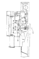
以下、本発明の好適な実施の形態を図面に基づいて説明する。図1は、本発明の一実施の形態を示す縦断正面図、図2は、要部の構成図である。
図1,図2において、立軸ポンプPは、軸受1,1に回転自在に支持された鉛直軸線Cを有する主軸2と、この主軸2の下部に固着した羽根車3と、この羽根車3を回転自在に収容した吐出しボウル4と、この吐出しボウル4の上側に連設されて主軸2を貫通させた縦方向の揚水管5と、この揚水管5の上側に連設された吐出しエルボ(吐出管)6とを備え、この吐出管6に方向変換機7を内蔵してある。
【0012】
方向変換機7は、縦軸線Cを有するケーシング8と、縦軸線Cに直交する横軸線C2を有して内端部がケーシング8の側壁部に水密に取付けられて側方にのびる軸受ケース9と、縦軸線C上にある入出力回転軸10と、横軸線C2上にある入力回転軸11とを備え、ケーシング8の内部は、上側の方向変換機構室12と、下側のメカニカルシール室13との上下二室に区画されており、軸受ケース9の内端面は方向変換機構室12に臨んでいる。また、ケーシング8の上端部開口は蓋部14によって水密に塞がれており、入出力回転軸10は、蓋部14における中心ボス部14Aに組付けられた軸受ケース15内の上下2段の軸受16A,16Bと、ケーシング8における方向変換機構室12内に設けた軸受支持部17に支持されている軸受17Cによって回転自在に支持されて、ケーシング8の下方と蓋部14の上方の二方向に延出している。なお、軸受16A,16B,17Cは、入出力回転軸10、主軸2、羽根車3などの回転体の重量を含むポンプ運転時の軸スラストを受推している。
【0013】
入力回転軸11は、軸受ケース9内の軸受18A,18Bに回転自在かつ横軸線C2方向の移動を不能に支持されている。軸受ケース9は、吐出しエルボ6の横向きの開口部19から吐出しエルボ6の外側に導出され、この軸受ケース9の外側に入力回転軸11の外端部が延出している。また、軸受ケース9の外端開口部は、入力回転軸11の回転を可能かつ水密に塞がれている。
【0014】
入力回転軸11の内端部には小傘歯車20が形成または固着され、この小傘歯車20が入出力回転軸10に固着されている大傘歯車21に噛み合うことで、直交変換伝達機能を有する傘歯車減速機を構成しており、小傘歯車20と大傘歯車21は方向変換機構室12の内部に位置している。また、メカニカルシール室13に上下2段のメカニカルシール22A,22Bが設けられ、上段のメカニカルシール22Aによって、方向変換機構室12内の潤滑油23がメカニカルシール室13に漏出したり、メカニカルシール室13内の潤滑油24が方向変換機構室12に漏出するのを防止するとともに、下段のメカニカルシール22Bによって、吐出しエルボ6内の揚水がメカニカルシール室13に侵入したり、メカニカルシール室13内の潤滑油24が吐出しエルボ6内に漏出するのを防止して、入出力回転軸10を回転自在かつ水密に軸封している。
【0015】
入出力回転軸10の下端部はカップリング25を介して主軸2に同時回転可能に連結され、入力回転軸11の外端部は、カップリング26と、たとえば電磁クラッチ機構によってなる第1クラッチ27などを介して、ディーゼルエンジンによってなる第1原動機28の横出力軸28Aを連結してある。また、入出力回転軸10の上端部は、カップリング29と、たとえば電磁クラッチ機構によってなる第2クラッチ30などを介して、電動機によってなる第2原動機31の縦出力軸31Aを連結してある。
【0016】
前記構成において、第1クラッチ27をON、第2クラッチ30をOFFに保持した状態で、第1原動機28を運転すると、横出力軸28Aの出力は、第1クラッチ27→カップリング26→方向変換機17の入力回転軸11→小傘歯車20→大傘歯車21→入出力回転軸10→カップリング25の第1動力伝達経路で主軸2に伝達され、主軸2を減速回転して立軸ポンプPの運転がなされる。また、方向変換機7が入力回転軸11側の小傘歯車20と入出力回転軸10側の大傘歯車21とを噛み合せた直交変換伝達機能を有する歯車減速機によって構成されているので、第1原動機28の高回転数を所定の減速比で立軸ポンプPの必要回転数まで減速して運転することができる。なお、この場合、第2クラッチ30がOFFに保持されているので、入出力回転軸10の回転が第2原動機31に影響をおよぼすことはない。
【0017】
一方、第1クラッチ27をOFF、第2クラッチ30をONに保持した状態で、第2原動機31を運転すると、縦出力軸31Aの出力は、第2クラッチ30→カップリング29→入出力回転軸10→カップリング25の第2動力伝達経路で主軸2に伝達され、主軸2を回転して立軸ポンプPの運転がなされる。なお、この場合、第1クラッチ27がOFFに保持されているので、入出力回転軸10の回転が第1原動機28に影響をおよぼすことはない。また、電動機によってなる第2原動機31を使用しているので、その極数を選択して機種を特定することにより、立軸ポンプPを適性な回転数で運転することができる。さらに、通常は、電動機によってなる第2原動機31によって立軸ポンプPを運転し、停電時には、ディーゼルエンジンによってなる第1原動機28によって立軸ポンプPを運転することができる。すなわち、立軸ポンプPの常時運転を実行することができる。
【0018】
しかも、方向変換機7が吐出しエルボ6に内蔵されていることにより、立軸ポンプPの上位に方向変換機7がはみ出すのを回避できる。このため、吐出しベンド6の横軸線Cxから第2原動機31の上端までの寸法H、つまりポンプ付設装置の上方向へのポンプ外はみ出し量Hを、図3に示すポンプ外はみ出し量H1よりも小さく(低く)抑えることができる。また、図1,図2におけるポンプ付設装置の横方向へのポンプ外はみ出し量を鉛直軸線Cから第1原動機28の外端までの寸法Lのみに低減して、図4に示す横方向へのポンプ外はみ出し量(L1+L2)よりも大幅(約1/2)に低減して、ポンプ付設装置の設置床面積を縮小することができるので、排水機場が小型化されて土木建設費を削減することができる。
【0019】
なお、前記実施の形態では、第1原動機28をディーゼルエンジンによって構成し、第2原動機31を電動機によって構成して説明しているが、第1原動機28を電動機によって構成し、第2原動機31をエンジン(たとえばガスタービンエンジン)によって構成してもよい。また、前記実施の形態のように、第2原動機31を電動機によって構成した場合には、方向変換機7のケーシング8における方向変換機構室12内に、たとえば遊星歯車構造の減速機を設け、この減速機により第2原動機31の縦出力軸31Aの回転を減速して入出力回転軸10に伝達するように構成してもよい。これにより、第2原動機31の回転数を所定の減速比で立軸ポンプPの必要回転数まで減速して運転することができる。さらに、第1原動機28と第2原動機31の両者を電動機によって構成してもよい。このように、第1,第2原動機28,31を電動機によって構成した場合には、第1クラッチ27と第2クラッチ30を省略しても、入出力回転軸10の回転が停止状態に保持されている側の第1原動機28または第2原動機31に影響をおよぼすことはない。
【0020】
【発明の効果】
以上説明したように、本発明に係る方向変換機内蔵立軸ポンプは構成されているので、以下のような格別の効果を奏する。
【0021】
すなわち、方向変換機が吐出管に内蔵されていることにより、立軸ポンプの上位に方向変換機がはみ出すのを回避できる。このため、ポンプ付設装置の上方向へのポンプ外はみ出し量を低く抑えることができるとともに、ポンプ付設装置の横方向へのポンプ外はみ出し量を鉛直軸線から第1原動機外端までの寸法のみに低減することができるので、ポンプ付設装置の設置床面積を縮小して、排水機場を小型化し土木建設費を削減することができる。
【図面の簡単な説明】
【図1】本発明の一実施の形態を示す縦断正面図である。
【図2】要部の構成図である。
【図3】第1従来例の概略正面図である。
【図4】第2従来例の概略正面図である。
【符号の説明】
1 軸受
2 主軸
3 羽根車
5 揚水管
6 吐出しエルボ(吐出管)
7 方向変換機
28 第1原動機
28A 第1原動機の横出力軸
31 第2原動機
31A 第2原動機の縦出力軸
C 縦軸線
P 立軸ポンプ[0001]
TECHNICAL FIELD OF THE INVENTION
The present invention relates to a vertical shaft pump with a built-in direction changer, and in particular, to reduce (lower) the amount of protrusion outside the pump in the upward direction of the pump attachment device, and to reduce the amount of protrusion of the pump attachment device in the lateral direction outside the pump. To a vertical shaft pump with a built-in direction changer.
[0002]
[Prior art]
Conventionally, as shown in FIG. 3, an orthogonal transformer (direction converter) 50 composed of a speed reducer is installed above a vertical shaft pump P, and the rotation of a horizontal output shaft 52 of a first prime mover 51 composed of a high-speed motor is vertically controlled. The rotation of the vertical output shaft 55 of the second prime mover 54, which is constituted by a low-speed motor installed above the direction changer 50, is changed through the direction changer 50. A vertical shaft pump configured to transmit power to the main shaft 53 is known (for example, see Non-Patent Document 1).
[0003]
On the other hand, as shown in FIG. 4, an orthogonal transformer (direction converter) 60 composed of a speed reducer is installed above the vertical shaft pump P, and the rotation of the lateral output shaft 62 of the first prime mover 61 composed of an electric motor is changed to a direction converter. At 60, the direction is changed to the vertical axis and transmitted to the main shaft 63, and the rotation of the horizontal output shaft 65 of the second prime mover 64 made of a diesel engine is changed to the vertical axis by the direction changer 60 to change the main shaft 63. (See, for example, Non-Patent Document 2).
[0004]
[Non-patent document 1]
River Pumping Facility Technology Association "River Pumping Facility Overview 2001"
Page 655 Cooling method
[Non-patent document 2]
River Pumping Facility Technology Association "River Pumping Facility Overview 2001"
339 pages Pumping only (10m3 / S pump)
[0006]
[Problems to be solved by the invention]
However, as shown in FIG. 3, an orthogonal transformer (direction converter) 50 including a reduction gear is installed above the vertical shaft pump P, and the vertical output shaft of the second prime mover 54 installed above the direction converter 50. In the former vertical shaft pump P configured to transmit the rotation of the shaft 55 to the main shaft 53 via the direction changer 50, the dimension H1 from the horizontal axis Cx of the discharge bend 56 to the upper end of the second prime mover 54, that is, the pump The amount of protrusion H1 outside the pump in the upward direction of the attachment device increases. For this reason, there is a problem that the drainage pump station is enlarged and civil engineering construction costs are increased.
[0007]
Also, as shown in FIG. 4, an orthogonal transformer (direction converter) 60 composed of a speed reducer is installed above the vertical shaft pump P, and the rotation of the horizontal output shaft 62 of the first prime mover 61 composed of an electric motor is represented on the vertical axis. The latter vertical shaft is configured to change the direction and transmit the rotation to the main shaft 63, and to change the direction of rotation of the lateral output shaft 65 of the second prime mover 64 composed of a diesel engine to the vertical axis and transmit the rotation to the main shaft 63. In the pump P, the dimension L1 from the vertical axis C1 to the outer end of the first prime mover 61 and the dimension L2 from the outer end of the second prime mover 64, that is, the amount (L1 + L2) of the protrusion outside the pump in the lateral direction of the pump attachment device is large. As a result, the installation floor area of the pump-equipped device is enlarged, and a pump installation part having a large area is required. For this reason, there is a problem that the drainage pump station is enlarged and civil engineering construction costs are increased.
[0008]
The present invention has been made in view of such circumstances, and suppresses the amount of protrusion outside the pump in the upward direction of the pump attachment device to be small (low), and the amount of protrusion of the pump attachment device in the lateral direction outside the pump. It is an object of the present invention to provide a vertical shaft pump with a built-in directional changer that can reduce the size of a drainage pump station and reduce the cost of civil engineering work by reducing the number of pumps.
[0009]
[Means for Solving the Problems]
In order to achieve the above object, a vertical changer-equipped vertical shaft pump according to the present invention includes a vertical main shaft rotatably supported by a bearing, an impeller fixed to a lower portion of the main shaft, and a penetrating through the main shaft. A vertical pump having a vertical pumping pipe and a discharge pipe connected to the upper side of the pumping pipe, wherein the rotation of the horizontal output shaft of the first motor is applied to the discharge pipe by a vertical axis along a first power transmission path. A direction changer for changing the direction and transmitting the rotation to the main shaft is built in, and the rotation of the vertical output shaft of the second prime mover is transmitted to the main shaft through a second power transmission path in the direction changer. It is characterized by having.
[0010]
According to the present invention, since the direction changer is incorporated in the discharge pipe, it is possible to prevent the direction changer from protruding above the pump, so that the amount of protrusion outside the pump in the upward direction of the pump attached device is reduced accordingly. Become. Further, the amount of protrusion outside the pump in the lateral direction of the pump attachment device can be reduced to only the amount of protrusion outside the pump of the first prime mover.
[0011]
BEST MODE FOR CARRYING OUT THE INVENTION
Hereinafter, preferred embodiments of the present invention will be described with reference to the drawings. FIG. 1 is a longitudinal sectional front view showing an embodiment of the present invention, and FIG. 2 is a configuration diagram of a main part.
1 and 2, a vertical shaft pump P includes a main shaft 2 having a vertical axis C rotatably supported by bearings 1 and 1, an impeller 3 fixed to a lower portion of the main shaft 2, and an impeller 3 A discharge bowl 4 rotatably housed, a vertical pumping pipe 5 connected to the upper side of the discharge bowl 4 and penetrating the main shaft 2, and a discharger connected to the upper side of the pumping pipe 5 An elbow (discharge pipe) 6 is provided, and the direction changer 7 is built in the discharge pipe 6.
[0012]
The direction changer 7 includes a casing 8 having a vertical axis C, and a bearing case 9 having a horizontal axis C2 perpendicular to the vertical axis C and having an inner end attached to a side wall of the casing 8 in a watertight manner and extending laterally. And an input / output rotary shaft 10 on a vertical axis C and an input rotary shaft 11 on a horizontal axis C2. The inside of the casing 8 includes an upper direction changing mechanism chamber 12 and a lower mechanical seal chamber. The bearing case 9 has an inner end face facing the direction change mechanism chamber 12. The upper end opening of the casing 8 is closed in a watertight manner by a lid 14, and the input / output rotary shaft 10 is provided in a two-stage upper and lower stages in a bearing case 15 attached to a center boss 14 </ b> A of the lid 14. It is rotatably supported by bearings 16A and 16B and a bearing 17C supported by a bearing support portion 17 provided in the direction changing mechanism chamber 12 of the casing 8, and has two directions below the casing 8 and above the lid 14. Has been extended to. The bearings 16A, 16B, and 17C receive the shaft thrust during the pump operation including the weight of the rotating body such as the input / output rotary shaft 10, the main shaft 2, and the impeller 3.
[0013]
The input rotary shaft 11 is supported by bearings 18A and 18B in the bearing case 9 so as to be rotatable and unable to move in the direction of the horizontal axis C2. The bearing case 9 is led out of the discharge elbow 6 through a lateral opening 19 of the discharge elbow 6, and the outer end of the input rotary shaft 11 extends outside the bearing case 9. Further, the outer end opening of the bearing case 9 is closed in a water-tight manner so that the input rotary shaft 11 can rotate.
[0014]
A small bevel gear 20 is formed or fixed to the inner end of the input rotating shaft 11, and the small bevel gear 20 meshes with a large bevel gear 21 fixed to the input / output rotating shaft 10, thereby providing an orthogonal transformation transmission function. The small bevel gear 20 and the large bevel gear 21 are located inside the direction changing mechanism chamber 12. The mechanical seal chamber 13 is provided with upper and lower two-stage mechanical seals 22A and 22B. The upper-stage mechanical seal 22A allows the lubricating oil 23 in the direction changing mechanism chamber 12 to leak into the mechanical seal chamber 13 or to be removed. 13 prevents the lubricating oil 24 from leaking into the direction changing mechanism chamber 12, and the lower mechanical seal 22B allows the pumped water in the discharge elbow 6 to enter the mechanical seal chamber 13, The input / output rotary shaft 10 is rotatably and watertightly sealed by preventing the lubricating oil 24 from being discharged and leaking into the elbow 6.
[0015]
The lower end of the input / output rotary shaft 10 is connected to the main shaft 2 via a coupling 25 so as to be able to rotate simultaneously. The outer end of the input rotary shaft 11 is connected to a coupling 26 and a first clutch 27 formed by, for example, an electromagnetic clutch mechanism. The transverse output shaft 28A of the first prime mover 28 composed of a diesel engine is connected via the like. The upper end of the input / output rotary shaft 10 is connected to a coupling 29 and a vertical output shaft 31A of a second prime mover 31 formed of an electric motor via a second clutch 30 formed of, for example, an electromagnetic clutch mechanism.
[0016]
In the above configuration, when the first prime mover 28 is operated with the first clutch 27 kept ON and the second clutch 30 kept OFF, the output of the lateral output shaft 28A changes from the first clutch 27 → the coupling 26 → the direction change. Rotating shaft 11 of the machine 17 → small bevel gear 20 → large bevel gear 21 → input / output rotating shaft 10 → transmitted to the main shaft 2 through the first power transmission path of the coupling 25, the main shaft 2 is rotated at a reduced speed, and the vertical shaft pump P Driving is performed. In addition, since the direction changer 7 is configured by a gear reducer having an orthogonal transformation transmission function in which the small bevel gear 20 on the input rotary shaft 11 side and the large bevel gear 21 on the input / output rotary shaft 10 are engaged. The operation can be performed while reducing the high rotation speed of one prime mover 28 to a required rotation speed of the vertical shaft pump P at a predetermined reduction ratio. In this case, since the second clutch 30 is kept OFF, the rotation of the input / output rotary shaft 10 does not affect the second prime mover 31.
[0017]
On the other hand, when the second prime mover 31 is operated with the first clutch 27 kept OFF and the second clutch 30 kept ON, the output of the vertical output shaft 31A is changed from the second clutch 30 → the coupling 29 → the input / output rotary shaft. 10 → the power is transmitted to the main shaft 2 through the second power transmission path of the coupling 25, and the main shaft 2 is rotated to operate the vertical shaft pump P. In this case, since the first clutch 27 is kept OFF, the rotation of the input / output rotary shaft 10 does not affect the first prime mover 28. Further, since the second prime mover 31 composed of an electric motor is used, the vertical shaft pump P can be operated at an appropriate rotation speed by selecting the number of poles and specifying the model. Further, normally, the vertical pump P can be operated by the second prime mover 31 composed of an electric motor, and in the event of a power failure, the vertical pump P can be operated by the first prime mover 28 composed of a diesel engine. That is, the constant operation of the vertical pump P can be executed.
[0018]
Moreover, since the directional change device 7 is incorporated in the discharge elbow 6, it is possible to prevent the directional change device 7 from protruding above the vertical shaft pump P. For this reason, the dimension H from the horizontal axis Cx of the discharge bend 6 to the upper end of the second prime mover 31, that is, the amount H of protrusion outside the pump in the upward direction of the pump-attached device is larger than the amount H1 of protrusion outside the pump shown in FIG. It can be kept small (low). Further, the amount of protrusion outside the pump in the lateral direction of the pump attachment device in FIGS. 1 and 2 is reduced to only the dimension L from the vertical axis C to the outer end of the first prime mover 28, and the lateral displacement shown in FIG. Since the amount of protrusion outside the pump (L1 + L2) can be significantly reduced (about 、) and the floor area for installing the pump-equipped device can be reduced, the size of the drainage station can be reduced and civil engineering construction costs can be reduced. Can be.
[0019]
In the above embodiment, the first prime mover 28 is constituted by a diesel engine, and the second prime mover 31 is constituted by an electric motor. However, the first prime mover 28 is constituted by an electric motor, and the second prime mover 31 is constituted by an electric motor. It may be constituted by an engine (for example, a gas turbine engine). Further, when the second prime mover 31 is constituted by an electric motor as in the above-described embodiment, for example, a speed reducer having a planetary gear structure is provided in the direction changing mechanism chamber 12 in the casing 8 of the direction changer 7. The rotation of the vertical output shaft 31A of the second prime mover 31 may be reduced and transmitted to the input / output rotation shaft 10 by the reduction gear. Thus, the second prime mover 31 can be operated at a reduced speed to a required speed of the vertical shaft pump P at a predetermined reduction ratio. Furthermore, both the first prime mover 28 and the second prime mover 31 may be constituted by electric motors. As described above, when the first and second motors 28 and 31 are configured by electric motors, the rotation of the input / output rotary shaft 10 is maintained in a stopped state even if the first clutch 27 and the second clutch 30 are omitted. The first or second prime mover 28 or 31 is not affected.
[0020]
【The invention's effect】
As described above, since the vertical-axis pump with a built-in direction changer according to the present invention is configured, the following special effects can be obtained.
[0021]
That is, since the direction changer is incorporated in the discharge pipe, it is possible to prevent the direction changer from protruding above the vertical shaft pump. For this reason, the amount of protrusion outside the pump in the upward direction of the pump attachment device can be suppressed low, and the amount of protrusion outside the pump in the lateral direction of the pump attachment device can be reduced to only the dimension from the vertical axis to the outer end of the first prime mover. Therefore, it is possible to reduce the installation floor area of the pump-equipped device, reduce the size of the drainage station, and reduce the cost of civil engineering construction.
[Brief description of the drawings]
FIG. 1 is a longitudinal sectional front view showing an embodiment of the present invention.
FIG. 2 is a configuration diagram of a main part.
FIG. 3 is a schematic front view of a first conventional example.
FIG. 4 is a schematic front view of a second conventional example.
[Explanation of symbols]
DESCRIPTION OF SYMBOLS 1 Bearing 2 Main shaft 3 Impeller 5 Pumping pipe 6 Discharge elbow (discharge pipe)
7 Direction changing machine 28 First motor 28A Horizontal output shaft 31 of first motor 31 Second motor 31A Vertical output shaft C of second motor Vertical axis P Vertical shaft pump