JP2004123992A - Carbonization treatment method and carbonization treatment system - Google Patents
Carbonization treatment method and carbonization treatment system Download PDFInfo
- Publication number
- JP2004123992A JP2004123992A JP2002292950A JP2002292950A JP2004123992A JP 2004123992 A JP2004123992 A JP 2004123992A JP 2002292950 A JP2002292950 A JP 2002292950A JP 2002292950 A JP2002292950 A JP 2002292950A JP 2004123992 A JP2004123992 A JP 2004123992A
- Authority
- JP
- Japan
- Prior art keywords
- superheated steam
- processing chamber
- contact
- processing
- carbonization
- Prior art date
- Legal status (The legal status is an assumption and is not a legal conclusion. Google has not performed a legal analysis and makes no representation as to the accuracy of the status listed.)
- Granted
Links
- 238000003763 carbonization Methods 0.000 title claims abstract description 70
- 238000011282 treatment Methods 0.000 title claims abstract description 37
- 238000000034 method Methods 0.000 title claims abstract description 33
- 238000010438 heat treatment Methods 0.000 claims abstract description 71
- 238000001035 drying Methods 0.000 claims abstract description 7
- 238000011221 initial treatment Methods 0.000 claims description 17
- 238000011084 recovery Methods 0.000 claims description 11
- 230000008569 process Effects 0.000 claims description 6
- 238000003756 stirring Methods 0.000 claims description 5
- 238000007599 discharging Methods 0.000 claims description 3
- 239000011800 void material Substances 0.000 claims description 3
- 239000000463 material Substances 0.000 abstract description 13
- 238000010000 carbonizing Methods 0.000 abstract description 10
- 239000010815 organic waste Substances 0.000 abstract description 3
- 239000010813 municipal solid waste Substances 0.000 abstract description 2
- 239000010802 sludge Substances 0.000 abstract description 2
- 239000002699 waste material Substances 0.000 abstract description 2
- 239000002023 wood Substances 0.000 abstract description 2
- 239000000843 powder Substances 0.000 abstract 1
- OKTJSMMVPCPJKN-UHFFFAOYSA-N Carbon Chemical compound [C] OKTJSMMVPCPJKN-UHFFFAOYSA-N 0.000 description 12
- 238000010586 diagram Methods 0.000 description 8
- 239000012535 impurity Substances 0.000 description 6
- 239000000428 dust Substances 0.000 description 5
- 230000000694 effects Effects 0.000 description 4
- 238000005516 engineering process Methods 0.000 description 4
- 238000009434 installation Methods 0.000 description 3
- XLYOFNOQVPJJNP-UHFFFAOYSA-N water Substances O XLYOFNOQVPJJNP-UHFFFAOYSA-N 0.000 description 3
- CURLTUGMZLYLDI-UHFFFAOYSA-N Carbon dioxide Chemical compound O=C=O CURLTUGMZLYLDI-UHFFFAOYSA-N 0.000 description 2
- 235000019735 Meat-and-bone meal Nutrition 0.000 description 2
- 230000003213 activating effect Effects 0.000 description 2
- 230000004913 activation Effects 0.000 description 2
- 230000005674 electromagnetic induction Effects 0.000 description 2
- 230000007613 environmental effect Effects 0.000 description 2
- HGUFODBRKLSHSI-UHFFFAOYSA-N 2,3,7,8-tetrachloro-dibenzo-p-dioxin Chemical compound O1C2=CC(Cl)=C(Cl)C=C2OC2=C1C=C(Cl)C(Cl)=C2 HGUFODBRKLSHSI-UHFFFAOYSA-N 0.000 description 1
- 230000009471 action Effects 0.000 description 1
- 238000001994 activation Methods 0.000 description 1
- 230000008901 benefit Effects 0.000 description 1
- 238000009835 boiling Methods 0.000 description 1
- 229910002092 carbon dioxide Inorganic materials 0.000 description 1
- 239000001569 carbon dioxide Substances 0.000 description 1
- 230000008859 change Effects 0.000 description 1
- 238000004140 cleaning Methods 0.000 description 1
- 238000001816 cooling Methods 0.000 description 1
- 238000005260 corrosion Methods 0.000 description 1
- 230000007797 corrosion Effects 0.000 description 1
- 239000011810 insulating material Substances 0.000 description 1
- 239000007788 liquid Substances 0.000 description 1
- 230000002093 peripheral effect Effects 0.000 description 1
- 238000004064 recycling Methods 0.000 description 1
- 230000009467 reduction Effects 0.000 description 1
- 229910001220 stainless steel Inorganic materials 0.000 description 1
- 239000010935 stainless steel Substances 0.000 description 1
Images


Classifications
-
- Y—GENERAL TAGGING OF NEW TECHNOLOGICAL DEVELOPMENTS; GENERAL TAGGING OF CROSS-SECTIONAL TECHNOLOGIES SPANNING OVER SEVERAL SECTIONS OF THE IPC; TECHNICAL SUBJECTS COVERED BY FORMER USPC CROSS-REFERENCE ART COLLECTIONS [XRACs] AND DIGESTS
- Y02—TECHNOLOGIES OR APPLICATIONS FOR MITIGATION OR ADAPTATION AGAINST CLIMATE CHANGE
- Y02E—REDUCTION OF GREENHOUSE GAS [GHG] EMISSIONS, RELATED TO ENERGY GENERATION, TRANSMISSION OR DISTRIBUTION
- Y02E50/00—Technologies for the production of fuel of non-fossil origin
- Y02E50/10—Biofuels, e.g. bio-diesel
-
- Y—GENERAL TAGGING OF NEW TECHNOLOGICAL DEVELOPMENTS; GENERAL TAGGING OF CROSS-SECTIONAL TECHNOLOGIES SPANNING OVER SEVERAL SECTIONS OF THE IPC; TECHNICAL SUBJECTS COVERED BY FORMER USPC CROSS-REFERENCE ART COLLECTIONS [XRACs] AND DIGESTS
- Y02—TECHNOLOGIES OR APPLICATIONS FOR MITIGATION OR ADAPTATION AGAINST CLIMATE CHANGE
- Y02W—CLIMATE CHANGE MITIGATION TECHNOLOGIES RELATED TO WASTEWATER TREATMENT OR WASTE MANAGEMENT
- Y02W30/00—Technologies for solid waste management
- Y02W30/50—Reuse, recycling or recovery technologies
- Y02W30/78—Recycling of wood or furniture waste
Abstract
Description
【0001】
【発明の属する技術分野】本発明は、生ごみ,汚泥,木材,肉骨粉,衣類屑等の有機系の廃棄物等からなる処理対象物を過熱水蒸気(加熱蒸気)で加熱して炭化させる炭化処理に係る技術分野に属する。
【0002】
【従来の技術】有機系の廃棄物等からなる処理対象物については、過熱水蒸気の噴射等による接触で直接的に加熱して炭化させる炭化処理が行われている。この炭化処理は、処理対象物を無酸素の還元雰囲気下で燃焼させることなく炭化させることができるため、二酸化炭素,ダイオキシン,悪臭等の発生を避けることができるとともに、処理物として活性炭を得ることができるという利点を有している。然しながら、この炭化処理では、処理対象物の乾燥,炭化,賦活化が並行的に進行するため、過熱水蒸気による加熱温度,加熱時間等を微妙に調整しないと、処理物として良質の活性炭を得ることができなくなる。このため、過熱水蒸気による加熱調整が容易で処理物として良質の活性炭を得ることのできる炭化処理技術の開発が切望されている。
【0003】
従来、前述の切望に応える炭化処理技術としては、例えば、以下に記載のものが知られている。
【特許文献1】特開2002−113439号公報。
特許文献1には、図7に示すように、処理対象物と相対的に低い温度の過熱水蒸気とを接触させて処理対象物を直接的に加熱して乾燥させる一次処理と、一次処理で乾燥された処理対象物と相対的に高い温度の過熱水蒸気とを接触させて処理対象物を直接的に加熱して炭化させる二次処理とを行う炭化処理技術が記載されている。
【0004】
特許文献1に係る炭化処理技術は、処理対象物の炭化に影響を与える水分を除去する乾燥を先行させた後に処理対象物を炭化,賦活化させる処理温度環境の異なる二段階処理を実行することで、過熱水蒸気による加熱温度,加熱時間等の微妙な調整を不要にしている。なお、過熱水蒸気は、二次処理で処理対象物を直接的に加熱した後に一次処理に送られて一次処理で処理対象物を直接的に加熱し、一次処理で処理対象物を直接的に加熱した後に回収され再過熱されて二次処理に送られる。
【0005】
【発明が解決しようとする課題】特許文献1に係る炭化処理技術では、処理対象物が過熱水蒸気で接触に加熱されるのみであるため、大量の処理対象物を連続的に処理する際に、処理対象物の温度分布が不均等になって迅速に適正な処理温度環境を形成することができなくなるという問題点がある。
【0006】
【課題を解決するための手段】前述の課題を解決するため、本発明に係る炭化処理方法は、次のような手段を採用する。
【0007】
即ち、請求項1に記載のように、処理対象物と相対的に低い温度の過熱水蒸気とを接触させて処理対象物を直接的に加熱して乾燥させる一次処理と、一次処理で乾燥された処理対象物と相対的に高い温度の過熱水蒸気とを接触させて処理対象物を直接的に加熱して炭化させる二次処理とを行う炭化処理方法において、一次処理,二次処理を含む複数処理で処理対象物と接触しない過熱水蒸気で処理対象物を間接的にも加熱することを特徴とする。
【0008】
この手段では、処理対象物と接触する過熱水蒸気(接触の過熱水蒸気)による直接的な加熱と処理対象物と接触しない過熱水蒸気(非接触の過熱水蒸気)による間接的な加熱との熱伝達形態の異なる二つの加熱系で処理対象物を加熱する。ここで過熱水蒸気とは温度が沸点以上の水蒸気をいうが、本発明では約200℃以上に加熱された水蒸気をいう。また、過熱水蒸気とはほぼ大気圧で利用されるものをいい、好適には例えば0.02Kg/cm2G前後の範囲のものをいう。
【0009】
また、請求項2に記載のように、請求項1の炭化処理方法において、処理対象物と接触しない過熱水蒸気は二次処理で処理対象物を間接的に加熱した後に一次処理に送られて一次処理で処理対象物を間接的に加熱することを特徴とする。
【0010】
この手段では、二次処理で使用された非接触の過熱水蒸気が一次処理で再利用される。非接触の過熱水蒸気は、接触の過熱水蒸気よりも温度低下率が小さいので、一次処理へ安定供給される。
【0011】
また、請求項3に記載のように、請求項2の炭化処理方法において、処理対象物と接触しない過熱水蒸気は一次処理で処理対象物を間接的に加熱した後に回収され再過熱されて二次処理に送られることを特徴とする。
【0012】
この手段では、処理対象物を加熱後して回収された非接触の過熱水蒸気が再過熱されて循環使用される。非接触の過熱水蒸気は不純物がない状態で回収され,清浄化工程を経る必要がない。
【0013】
さらに、前述の課題を解決するため、本発明に係る炭化処理システムは、次のような手段を採用する。
【0014】
即ち、請求項4に記載のように、処理対象物と相対的に低い温度の過熱水蒸気とを接触させて処理対象物を直接的に加熱して乾燥させる一次処理室と、一次処理室で乾燥された処理対象物と相対的に高い温度の過熱水蒸気とを接触させて処理対象物を直接的に加熱して炭化させる二次処理室と、過熱水蒸気を生成する過熱水蒸気生成装置と、一次処理室,二次処理室と過熱水蒸気生成装置との間に配設され処理対象物と接触する過熱水蒸気が供給される接触系過熱水蒸気供給路とを備えた炭化処理システムにおいて、一次処理室,二次処理室を含む複数処理室に処理対象物と接触しない過熱空気で加熱されて処理対象物を間接的に加熱する加熱構造が設けられ、一次処理室,二次処理室の加熱構造と過熱水蒸気生成装置との間に処理対象物と接触しない過熱水蒸気が供給される非接触系過熱水蒸気供給路が配設されていることを特徴とする。
【0015】
この手段では、前述の請求項1の炭化処理方法を実施するために、一次処理室,二次処理室に処理対象物を間接的に加熱する加熱構造を設け、接触の過熱水蒸気を供給する接触系過熱水蒸気供給路と非接触の過熱水蒸気を供給する非接触系過熱水蒸気供給路とを別系統で配設する。接触系過熱水蒸気供給路では処理対象物に接触した後に不純物を有することとなる過熱水蒸気が供給され、非接触系過熱水蒸気供給路では処理対象物に接触しない不純物のない過熱水蒸気が供給される。
【0016】
また、請求項5に記載のように、請求項4の炭化処理システムにおいて、非接触系過熱水蒸気供給路は二次処理室の加熱構造のアウトレットポートと一次処理室の加熱構造のインレットポートとを接続し一次処理室,二次処理室の加熱構造を直列に接続していることを特徴とする。
【0017】
この手段では、前述の請求項2の炭化処理方法を実施するために、非接触系過熱水蒸気供給路が一次処理室,二次処理室の加熱構造を直列に接続する。直列接続により,一次処理室と二次処理室との間における温度低下率が小さくなる。
【0018】
また、請求項6に記載のように、請求項5の炭化処理システムにおいて、一次処理室の加熱構造のアウトレットポートと過熱水蒸気生成装置との間に一次処理室の加熱構造を加熱した過熱水蒸気を回収する非接触系過熱水蒸気回収路が配設されていることを特徴とする。
【0019】
この手段では、前述の請求項3の炭化処理方法を実施するために、非接触の過熱水蒸気を回収する非接触系過熱水蒸気回収路が配設される。非接触系過熱水蒸気は不純物のない状態で回収される。
【0020】
また、請求項7に記載のように、請求項4〜6のいずれかの炭化処理システムにおいて、一次処理室,二次処理室の加熱構造は処理対象物,過熱水蒸気が接触する筒形の処理筒の外側に処理対象物と接触しないに過熱水蒸気が流通する空隙を形成するジャケット又は外管を被せてなることを特徴とする。
【0021】
この手段では、一次処理室,二次処理室にジャケット構造あるいは二重管構造で加熱構造が設けられる。その結果,処理対象物の異同による温度変化が外側から可能な限り抑えられる。
【0022】
また、請求項8に記載のように、請求項4〜7のいずれかの炭化処理システムにおいて、一次処理室,二次処理室は処理対象物の大気との接触を避ける非開放構造で接続されていることを特徴とする。
【0023】
この手段では、一次処理室,二次処理室が非開放構造で連通される。
【0024】
また、請求項9に記載のように、請求項4〜8のいずれかの炭化処理システムにおいて、一次処理室または一次処理室,二次処理室の双方に処理対象物と接触した過熱水蒸気を外部に排出する接触系過熱水蒸気排出路を接続し、接触系過熱水蒸気排出路の中途に排出される過熱水蒸気の熱を回収する熱交換器を設置したことを特徴とする。
【0025】
この手段では、熱交換によって排出される直接の過熱水蒸気から熱が回収される。
【0026】
また、請求項10に記載のように、請求項4〜9のいずれかの炭化処理システムにおいて、一次処理室,二次処理室の内部において処理対象物を撹拌しながら過熱水蒸気に接触させつつ移動させる撹拌接触手段を設置したことを特徴とする。
【0027】
この手段では、処理対象物が撹拌されることで過熱水蒸気との接触率が高められ、しかも均一な接触を得たうえで移動される。
【0028】
さらに、請求項11に記載のように、請求項4〜10のいずれかの炭化処理システムにおいて、一次処理室を上部に配置するとともに二次処理室を下部に配置し、一次処理室と二次処理室との間には処理対象物を落下させる排出路を配置したことを特徴とする。
【0029】
この手段では、一次処理室で乾燥された処理対象物が排出路から自重で落下して二次処理室に移動する。上下配置構造により設置スペースが抑えられる。
【0030】
さらに、請求項12に記載のように、請求項4〜10のいずれかの炭化処理システムにおいて、一次処理室と二次処理室を左右に並列して配置し、一次処理室と二次処理室との間には処理対象物を移動させる移動手段を備えた排出路を配置したことを特徴とする。
【0031】
この手段では、移動手段により一時処理室から二次処理室へと対象処理物が移動する。左右配置構造により低い建屋で設置可能となる。
【0032】
【発明の実施の形態】以下、本発明に係る炭化処理方法および炭化処理システムの実施の形態を図1〜図6に基づいて説明する。
【0033】
図1,図2は、本発明に係る炭化処理方法および炭化処理システムの実施の形態(1)を示すものである。
【0034】
この実施の形態では、特許文献1に係る炭化処理技術と同様の処理温度環境の異なる二段階処理を実行するものを示してある。
【0035】
一次処理が行われる一次処理室1は、処理筒11の外側に加熱構造12が配置された2重管構造ないしはジャケット構造に形成されている。
【0036】
一次処理室1の処理筒11は、耐腐食性の良好なステンレス材で筒形に形成され処理対象物Pが収容される本体部11aを備え、本体部11aの端面に過熱水蒸気が供給,排出されるインレットポート11b,アウトレットポート11cが設けられ、本体部11a周面に処理対象物Pが投入,排出される筒形の投入筒11d,排出筒11eとが設けられている。本体部11aの内部には、本体部11aの軸方向へ処理対象物Pを撹拌しながら移動させる撹拌接触手段としての回転羽根11fと、インレットポート11bに接続して収容された処理対象物Pに過熱水蒸気を噴射するノズル(図示せず)とが設置されている。
【0037】
一次処理室1の加熱構造12は、断熱材等で過熱水蒸気が流通する空隙12aを形成するジャケット12bを処理筒11に被せてなるもので、過熱水蒸気が供給,排出されるインレットポート12c,アウトレットポート12dを備えている。
【0038】
二次処理が行われる二次処理室2は、一次処理室1と同様に、処理筒21(本体部21a,インレットポート21b,アウトレットポート21c,投入筒21d,排出筒21e,回転羽根21f)と、加熱構造22(空隙22a,ジャケット22b,インレットポート22c,アウトレットポート22d)とを備えている。ただし、投入筒21dは、一次処理室1の処理筒11の排出筒11eと接続一体化され、一次処理室1の処理筒11の内部と二次処理室2の処理筒21の内部とを大気との接触を避けた非開放構造で連通している。また、排出筒21eは、適当な冷却装置(図示せず)が付設されて処理対象物Pが炭化処理された処理物P’が排出されるようになっている。
【0039】
一次処理室1,二次処理室2には、過熱水蒸気を生成する過熱水蒸気生成装置3から過熱水蒸気が二系統で供給される。なお、過熱水蒸気生成装置3は、給水装置4から給水された水を加熱して水蒸気を生成するボイラ式等の水蒸気生成装置5から供給された水蒸気を過熱して過熱水蒸気を生成するもので、電磁誘導式,バーナ式等を自由に選択することができる。
【0040】
過熱水蒸気の一つの供給系は、過熱水蒸気生成装置3から一次処理室1の処理筒11のインレットポート11bと二次処理室2の処理筒21のインレットポート21bとに分岐配設された接触系過熱水蒸気供給路6である。なお、この接触系過熱水蒸気供給路6には、一次処理室1の処理筒11のアウトレットポート11cと二次処理室2の処理筒21のアウトレットポート21cとに接続され処理対象物Pと接触した過熱水蒸気(処理ガス)を外部に排出する接触系過熱水蒸気排出路8が対応して配設されている。接触系過熱水蒸気排出路8は、途中に熱交換器10,集塵装置20を介して端末の排気装置30まで配設されている。熱交換器10は、排出される過熱水蒸気(処理ガス)を回収すれば、前述の水蒸気生成装置5の水蒸気生成のための熱源やその他の熱源として利用する熱リサイクルに寄与することができる。集塵装置20は、過熱水蒸気(処理ガス)に含まれている粉塵を捕捉するとともに気液を分離する。この集塵装置20には、分離された水を下水道,河川に排出可能な環境基準にまで清浄化する排水装置40が接続されている。排気装置30は、集塵装置20で分離されたガスを大気に排出可能な環境基準にまで清浄化する。
【0041】
過熱水蒸気の他の一つの供給系は、過熱水蒸気生成装置3から二次処理室2の加熱構造22のインレットポート22cに配設され、続いて二次処理室2の加熱構造22のアウトレットポート22dから一次処理室1の加熱構造12のインレットポート12cに配設された非接触系過熱水蒸気供給路7である。この非接触系過熱水蒸気供給路7は、二次処理室2の加熱構造22と一次処理室1の加熱構造12とを直列に接続していることになる。なお、この非接触系過熱水蒸気供給路7には、一次処理室1の処理筒11の加熱構造12のアウトレットポート12dと過熱水蒸気生成装置3との間を接続する非接触系過熱水蒸気回収路9が対応して配設されている。
【0042】
なお、前述の構成に加えて、過熱水蒸気の供給等のために各種のバルブ,ポンプ等が備えられる(図2では省略されている。)。
【0043】
この実施の形態では、過熱水蒸気生成装置3から接触系過熱水蒸気供給路6を通じて、一次処理室1の処理筒11に相対的に低い温度(例えば、150〜500℃、好ましくは350〜400℃)の過熱水蒸気が供給され、二次処理室2の処理筒21に相対的に高い温度(例えば、450〜700℃、好ましくは500〜600℃)の過熱水蒸気が供給される。一次処理室1の処理筒11では、処理対象物Pが相対的に低い温度の過熱水蒸気に接触して直接的に加熱されて乾燥される。一次処理室1の処理筒11で乾燥された処理対象物Pは、大気と接触することなく(還元雰囲気が維持されたまま)二次処理室2の処理筒21に送られ、相対的に高い温度の過熱水蒸気に接触して直接的に加熱されて炭化,賦活化される。この場合の過熱水蒸気による処理時間は,処理対象物の種類や分量あるいは過熱温度などによって相違する。例えばおが屑の場合には、1時間当り約300リットルを処理し,約100リットルの活性炭を得た。肉骨粉の場合には,1時間当り100Kgを処理し、30〜40Kgの活性炭を得た。この結果,良質の活性炭からなる処理物P’を大量に得ることができる。
【0044】
また、この実施の形態では、過熱水蒸気生成装置3から非接触系過熱水蒸気供給路7を通じて、まず二次処理室2の加熱構造22に相対的に高い温度(例えば、500〜800℃)の過熱水蒸気が供給される。二次処理室2の加熱構造22では、過熱水蒸気により二次処理室2の処理筒21を外周から加熱することで、二次処理室2の処理筒21の内部の処理対象物Pを間接的に加熱する。このため、接触の過熱水蒸気による直接的な加熱と非接触の過熱水蒸気による間接的な加熱との熱伝達形態の異なる二つの加熱系で処理対象物Pが加熱され、処理対象物Pを炭化,賦活化するに適正な処理温度環境が迅速に形成される。この結果、良質の炭化物からなる処理物P’を大量に得ることができる。
【0045】
続いて、二次処理室2の加熱構造22で吸熱され相対的に低い温度(例えば、200〜500℃)になった過熱水蒸気が一次処理室1の加熱構造12に供給される。一次処理室1の加熱構造12では、再利用の過熱水蒸気により一次処理室1の処理筒11を外周から加熱することで、一次処理室1の処理筒11の内部の処理対象物Pを間接的に加熱する。このため、接触の過熱水蒸気による直接的な加熱と非接触の過熱水蒸気による間接的な加熱との熱伝達形態の異なる二つの加熱系で処理対象物Pが加熱され、処理対象物Pを乾燥するに適正な処理温度環境が迅速に形成される。この結果、処理対象物Pが後続の二次処理に好適な水分にまで迅速に乾燥される。
【0046】
一次処理室1の加熱構造12から排出された非接触の過熱水蒸気(水蒸気)は、非接触系過熱水蒸気回収路9を通じて過熱水蒸気生成装置3に回収される。そして、回収された過熱水蒸気は、過熱水蒸気生成装置3で再加熱される。なお、回収された過熱水蒸気は、処理対象物Pと接触せず不純物が含まれていないため、ジュール熱で過熱される微細な発熱体を有する電磁誘導式の過熱水蒸気生成装置3での再加熱をも可能にする。
【0047】
また、図2に示すように、一次処理室1を上部に、二次処理室2を下部にそれぞれ配置することができる。処理室1,2の上下間には、端部に位置して排出路として排出筒11eが接続され、一次処理室1の端部で乾燥された処理対象物が排出筒11eから自重で二次処理室2に落下する。上下配置構造となって,処理室1,2の設置スペースが小さく抑えられる。
【0048】
さらに,図1,図2に示すように、加熱水蒸気生成装置3から接触系過熱水蒸気供給路6と非接触系過熱水蒸気供給路7とを別配管としているが、接続部位手前まで共通配管とすることも可能である。
【0049】
図3,図4は、本発明に係る炭化処理方法および炭化処理システムの実施の形態(2)を示すものである。
【0050】
この実施の形態では、前述の実施の形態(1)の接触系過熱水蒸気供給路6を二次処理室2の処理筒21のアウトレットポート21cと一次処理室1の処理筒11のインレットポート11bとの間にも配設してある。従って、二次処理室2の処理筒21のアウトレットポート21cは、一次処理室1の処理筒11を介して接触系過熱水蒸気排出路8に接続されている。
【0051】
この実施の形態によると、前述の実施の形態(1)と同様の作用,効果を奏することに加えて、二次処理室2の処理筒21から排出される過熱水蒸気(処理ガス)の熱を一次処理室1の処理筒11で再利用することができる。処理筒21から排出される過熱水蒸気(処理ガス)は、接触系過熱水蒸気供給路6に合流して希釈化して利用するか、あるいは全量をそのまま利用するかなどが必要時に応じて選択される。なお、再利用される過熱水蒸気は、二次処理室2の処理筒21での処理対象物Pとの接触で不純物を含んでいるものの、処理対象物Pの炭化,賦活化に供するのではないため何等支障を生ずることはない。
【0052】
図5,図6は、本発明に係る炭化処理方法および炭化処理システムの実施の形態(3)を示すものである。
【0053】
この実施の形態では、前述の実施の形態(2)の接触系過熱水蒸気供給路6の一次処理室1の処理筒11のインレットポート11bへの直接の接続を遮断している。
【0054】
この実施の形態によると、前述の実施の形態(1),(2)と同様の作用,効果を奏することに加えて、二次処理室2の処理筒21から排出される過熱水蒸気(処理ガス)の熱の再利用のみで一次処理室1の処理筒11で処理対象物Pを乾燥させ、接触系過熱水蒸気排出路8へ排出される過熱水蒸気の熱を低減することができる。
【0055】
図7は、本発明に係る炭化処理方法および炭化処理システムの実施の形態(4)を示すものである。
【0056】
この実施の形態では、、一次処理室1と二次処理室2とを水平に配列し,処理室1,2の端部間の底側に位置して排出筒11eで接続し,排出筒11eには移動手段23を内装している。移動手段23としてはスクリューコンベアなどが用いられる。
【0057】
この実施の形態によると、前述の実施の形態(1),(2),(3)と同様の作用,効果を奏することに加えて、設置構造が簡略化されるうえに低屋根構造物内に設置することができる。
【0058】
以上、図示した実施の形態の外に、一次処理,二次処理をさらに複数段階に構成することも可能である。
【0059】
【発明の効果】以上のように、本発明に係る炭化処理方法および炭化処理システムは、接触の過熱水蒸気による直接的な加熱と非接触の過熱水蒸気による間接的な加熱との熱伝達形態の異なる二つの加熱系で処理対象物を加熱するため、迅速に適正な処理温度環境を形成することができる効果がある。
【図面の簡単な説明】
【図1】本発明に係る炭化処理方法および炭化処理システムの実施の形態(1)を示す過熱水蒸気の供給,回収系統図である。
【図2】図1の詳細な装置構成図である。
【図3】本発明に係る炭化処理方法および炭化処理システムの実施の形態(2)を示す過熱水蒸気の供給,回収系統図である。
【図4】図2の詳細な装置構成図である。
【図5】本発明に係る炭化処理方法および炭化処理システムの実施の形態(3)を示す過熱水蒸気の供給,回収系統図である。
【図6】図3の詳細な装置構成図である。
【図7】本発明に係る炭化処理方法および炭化処理システムの実施の形態(4)を示す過熱水蒸気の詳細な位置構成図である。
【図8】従来例を示す過熱水蒸気の供給,回収系統図である。
【符号の説明】
1 一次処理室
11 処理筒
11b インレットポート
11c アウトレットポート
12 加熱構造
12a 空隙
12b ジャケット
12c インレットポート
12d アウトレットポート
2 二次処理室
21 処理筒
21b インレットポート
21c アウトレットポート
22 加熱構造
22a 空隙
22b ジャケット
22c インレットポート
22d アウトレットポート
3 過熱水蒸気生成装置
5 水蒸気生成装置
6 接触系過熱水蒸気供給路
7 非接触系過熱水蒸気供給路
8 接触系過熱水蒸気排出路
9 非接触系過熱水蒸気回収路
10 熱交換器
P 処理対象物
P’ 処理物[0001]
BACKGROUND OF THE
[0002]
2. Description of the Related Art Carbonization treatment is performed on an object to be treated, such as an organic waste, by directly heating and carbonizing it by contact with superheated steam or the like. In this carbonization treatment, the object to be treated can be carbonized without burning in an oxygen-free reducing atmosphere, so that generation of carbon dioxide, dioxin, odor, etc. can be avoided, and activated carbon can be obtained as a treatment object. It has the advantage that it can be done. However, in this carbonization process, drying, carbonization, and activation of the object to be processed proceed in parallel. Therefore, unless the heating temperature and heating time with superheated steam are delicately adjusted, a high-quality activated carbon can be obtained as a processed material. Can not be done. For this reason, there is a strong demand for the development of a carbonization technology capable of easily heating with superheated steam and obtaining high-quality activated carbon as a treated product.
[0003]
Conventionally, for example, the following ones have been known as carbonization techniques that meet the above-mentioned needs.
[Patent Document 1] JP-A-2002-113439.
In
[0004]
The carbonization processing technology according to
[0005]
In the carbonization technology according to
[0006]
Means for Solving the Problems In order to solve the above-mentioned problems, the carbonization method according to the present invention employs the following means.
[0007]
That is, as described in
[0008]
In this means, the heat transfer form of direct heating by superheated steam (contact superheated steam) in contact with the object to be processed and indirect heating by superheated steam (non-contact superheated steam) not in contact with the object to be processed is The object to be processed is heated by two different heating systems. Here, the superheated steam refers to steam having a temperature equal to or higher than the boiling point, but in the present invention, refers to steam heated to about 200 ° C. or higher. Further, the superheated steam refers to a steam used at substantially atmospheric pressure, and preferably a steam having a range of, for example, about 0.02 kg / cm 2 G.
[0009]
Further, as described in
[0010]
In this means, the non-contact superheated steam used in the secondary treatment is reused in the primary treatment. Since the non-contact superheated steam has a lower temperature reduction rate than the contact superheated steam, it is stably supplied to the primary treatment.
[0011]
According to a third aspect of the present invention, in the carbonization method according to the second aspect, the superheated steam that does not come into contact with the object to be treated is recovered and reheated after indirectly heating the object to be treated in the primary treatment. It is sent to processing.
[0012]
In this means, the non-contact superheated steam collected after heating the object to be treated is reheated and reused. The non-contact superheated steam is recovered without any impurities and does not need to go through a cleaning step.
[0013]
Furthermore, in order to solve the above-mentioned problem, the carbonization processing system according to the present invention employs the following means.
[0014]
That is, as described in claim 4, a primary processing chamber in which the processing object is brought into contact with superheated steam at a relatively low temperature to directly heat and dry the processing object, and drying in the primary processing chamber. A secondary processing chamber for directly heating and carbonizing the processing object by bringing the processed processing object into contact with superheated steam at a relatively high temperature, a superheated steam generator for generating superheated steam, and a primary processing And a contact-type superheated steam supply passage provided between the secondary treatment chamber and the superheated steam generator and provided with superheated steam that comes into contact with the object to be treated. A heating structure that is heated by superheated air that does not come into contact with the processing object and indirectly heats the processing object is provided in a plurality of processing chambers including the next processing chamber, and the heating structure of the primary processing chamber and the secondary processing chamber and the superheated steam. Between the generator and the processing object Non-contact type superheated steam supply line not touch superheated steam is supplied, characterized in that it is arranged.
[0015]
In this means, in order to carry out the carbonization method of the first aspect, a heating structure for indirectly heating the object to be processed is provided in the primary processing chamber and the secondary processing chamber, and a contacting superheated steam is supplied. The system superheated steam supply path and the non-contact system superheated steam supply path for supplying non-contact superheated steam are provided in separate systems. In the contact-type superheated steam supply path, superheated steam having impurities after being brought into contact with the object to be treated is supplied, and in the non-contact type superheated steam supply path, superheated steam without impurities which does not contact the object to be treated is supplied.
[0016]
According to a fifth aspect of the present invention, in the carbonization processing system of the fourth aspect, the non-contact superheated steam supply path includes an outlet port of the heating structure of the secondary processing chamber and an inlet port of the heating structure of the primary processing chamber. It is characterized in that the heating structures of the primary processing chamber and the secondary processing chamber are connected in series.
[0017]
In this means, the non-contact superheated steam supply path connects the heating structures of the primary processing chamber and the secondary processing chamber in series in order to carry out the carbonizing method of the second aspect. The series connection reduces the rate of temperature decrease between the primary processing chamber and the secondary processing chamber.
[0018]
According to a sixth aspect of the present invention, in the carbonization processing system of the fifth aspect, the superheated steam that has heated the heating structure of the primary processing chamber is provided between the outlet port of the heating structure of the primary processing chamber and the superheated steam generator. A non-contact superheated steam recovery passage for recovery is provided.
[0019]
In this means, a non-contact superheated steam recovery passage for collecting non-contact superheated steam is provided in order to carry out the carbonization method of the third aspect. The non-contact superheated steam is recovered without any impurities.
[0020]
According to a seventh aspect of the present invention, in the carbonization processing system according to any one of the fourth to sixth aspects, the heating structure of the primary processing chamber and the secondary processing chamber has a cylindrical processing in which an object to be processed and superheated steam come into contact. It is characterized in that the outer tube is covered with a jacket or an outer tube that forms a space through which superheated steam flows without contacting the object to be treated.
[0021]
In this means, a heating structure having a jacket structure or a double tube structure is provided in the primary processing chamber and the secondary processing chamber. As a result, the temperature change due to the difference in the processing object is suppressed as much as possible from the outside.
[0022]
In the carbonization processing system according to any one of claims 4 to 7, the primary processing chamber and the secondary processing chamber are connected by a non-open structure that avoids contact of the processing object with the atmosphere. It is characterized by having.
[0023]
In this means, the primary processing chamber and the secondary processing chamber are communicated in a non-open structure.
[0024]
According to a ninth aspect of the present invention, in the carbonization processing system according to any one of the fourth to eighth aspects, the superheated steam in contact with the object to be processed is externally supplied to the primary processing chamber or both the primary processing chamber and the secondary processing chamber. And a heat exchanger for recovering the heat of the superheated steam discharged in the middle of the contact-type superheated steam discharge passage.
[0025]
In this means, heat is recovered from the direct superheated steam discharged by the heat exchange.
[0026]
According to a tenth aspect of the present invention, in the carbonization processing system according to any one of the fourth to ninth aspects, the object to be processed is moved while being brought into contact with the superheated steam while being stirred inside the primary processing chamber and the secondary processing chamber. It is characterized in that a stirring contact means for causing the stirring is provided.
[0027]
In this means, the object to be treated is agitated to increase the contact ratio with the superheated steam, and is moved after obtaining uniform contact.
[0028]
Further, as described in
[0029]
In this means, the processing target dried in the primary processing chamber falls by its own weight from the discharge path and moves to the secondary processing chamber. The installation space is suppressed by the vertical arrangement structure.
[0030]
Furthermore, as described in
[0031]
In this means, the target processing object is moved from the temporary processing chamber to the secondary processing chamber by the moving means. It can be installed in a low building due to the left and right arrangement structure.
[0032]
DESCRIPTION OF THE PREFERRED EMBODIMENTS Embodiments of a carbonization method and a carbonization system according to the present invention will be described below with reference to FIGS.
[0033]
1 and 2 show an embodiment (1) of a carbonizing method and a carbonizing system according to the present invention.
[0034]
In this embodiment, a two-stage process having a different processing temperature environment similar to the carbonization technology according to
[0035]
The
[0036]
The
[0037]
The
[0038]
Like the
[0039]
Superheated steam is supplied to the
[0040]
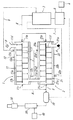
One supply system of the superheated steam is provided by a contact system branched from the
[0041]
Another supply system of the superheated steam is provided from the
[0042]
In addition to the above-described configuration, various valves, pumps, and the like are provided for supplying superheated steam (not shown in FIG. 2).
[0043]
In this embodiment, a relatively low temperature (for example, 150 to 500 ° C., preferably 350 to 400 ° C.) is applied to the
[0044]
In this embodiment, the superheated steam at a relatively high temperature (for example, 500 to 800 ° C.) is first supplied from the
[0045]
Subsequently, superheated steam that has been absorbed by the
[0046]
The non-contact superheated steam (steam) discharged from the
[0047]
Further, as shown in FIG. 2, the
[0048]
Further, as shown in FIGS. 1 and 2, the contact superheated
[0049]
FIGS. 3 and 4 show an embodiment (2) of a carbonization method and a carbonization system according to the present invention.
[0050]
In this embodiment, the contact-system superheated
[0051]
According to this embodiment, in addition to having the same action and effect as the above-described embodiment (1), the heat of the superheated steam (processing gas) discharged from the
[0052]
5 and 6 show an embodiment (3) of a carbonization method and a carbonization system according to the present invention.
[0053]
In this embodiment, the direct connection to the
[0054]
According to this embodiment, in addition to having the same operation and effect as the above-described embodiments (1) and (2), in addition to the superheated steam (processing gas) discharged from the
[0055]
FIG. 7 shows an embodiment (4) of the carbonization method and the carbonization system according to the present invention.
[0056]
In this embodiment, the
[0057]
According to this embodiment, in addition to having the same operations and effects as those of the above-described embodiments (1), (2), and (3), the installation structure is simplified and the inside of the low roof structure is reduced. Can be installed in
[0058]
As described above, in addition to the illustrated embodiment, the primary processing and the secondary processing can be further configured in a plurality of stages.
[0059]
As described above, the carbonization method and the carbonization system according to the present invention differ in the form of heat transfer between direct heating by contact superheated steam and indirect heating by non-contact superheated steam. Since the object to be processed is heated by the two heating systems, there is an effect that an appropriate processing temperature environment can be quickly formed.
[Brief description of the drawings]
FIG. 1 is a supply and recovery system diagram of superheated steam, showing an embodiment (1) of a carbonization method and a carbonization system according to the present invention.
FIG. 2 is a detailed device configuration diagram of FIG.
FIG. 3 is a supply and recovery system diagram of superheated steam showing an embodiment (2) of a carbonization method and a carbonization system according to the present invention.
FIG. 4 is a detailed device configuration diagram of FIG. 2;
FIG. 5 is a supply and recovery system diagram of superheated steam, showing an embodiment (3) of a carbonization method and a carbonization system according to the present invention.
FIG. 6 is a detailed device configuration diagram of FIG. 3;
FIG. 7 is a detailed position configuration diagram of superheated steam, showing an embodiment (4) of a carbonization method and a carbonization system according to the present invention.
FIG. 8 is a diagram showing a supply and recovery system of superheated steam showing a conventional example.
[Explanation of symbols]
1
Claims (12)
一次処理,二次処理を含む複数処理で処理対象物と接触しない過熱水蒸気で処理対象物を間接的にも加熱することを特徴とする炭化処理方法。A primary treatment in which a treatment object is brought into contact with superheated steam at a relatively low temperature to directly heat and dry the treatment object, and a superheat at a relatively high temperature relative to the treatment object dried in the primary treatment In a carbonization treatment method of performing a secondary treatment in which the treatment target is directly heated and carbonized by contacting with steam,
A carbonization method characterized by indirectly heating an object to be treated with superheated steam that does not come into contact with the object in a plurality of treatments including a primary treatment and a secondary treatment.
一次処理室,二次処理室を含む複数処理室に処理対象物と接触しない過熱空気で加熱されて処理対象物を間接的に加熱する加熱構造が設けられ、一次処理室,二次処理室の加熱構造と過熱水蒸気生成装置との間に処理対象物と接触しない過熱水蒸気が供給される非接触系過熱水蒸気供給路が配設されていることを特徴とする炭化処理システム。A primary processing chamber for directly heating and drying the processing object by bringing the processing object into contact with superheated steam at a relatively low temperature, and a relatively high temperature for the processing object dried in the primary processing chamber A secondary processing chamber that directly heats and carbonizes the object to be treated by contacting the superheated steam with a superheated steam, a superheated steam generator that generates superheated steam, a primary processing chamber, a secondary processing chamber, and a superheated steam generator And a contact-type superheated steam supply path to which superheated steam that is disposed between and is in contact with the object to be treated is provided.
A heating structure is provided in a plurality of processing chambers including a primary processing chamber and a secondary processing chamber to heat the processing object indirectly by being heated by superheated air that does not come into contact with the processing object. A carbonization treatment system, wherein a non-contact superheated steam supply path is provided between a heating structure and a superheated steam generation device, to which superheated steam that is not in contact with an object to be treated is supplied.
非接触系過熱水蒸気供給路は二次処理室の加熱構造のアウトレットポートと一次処理室の加熱構造のインレットポートとを接続し一次処理室,二次処理室の加熱構造を直列に接続していることを特徴とする炭化処理システム。In the carbonization processing system according to claim 4,
The non-contact superheated steam supply passage connects the outlet port of the heating structure of the secondary processing chamber and the inlet port of the heating structure of the primary processing chamber, and connects the heating structures of the primary processing chamber and the secondary processing chamber in series. A carbonization processing system characterized by the above-mentioned.
一次処理室の加熱構造のアウトレットポートと過熱水蒸気生成装置との間に一次処理室の加熱構造を加熱した過熱水蒸気を回収する非接触系過熱水蒸気回収路が配設されていることを特徴とする炭化処理システム。In the carbonization processing system according to claim 5,
A non-contact type superheated steam recovery passage for collecting superheated steam which has heated the heating structure of the primary processing chamber is provided between an outlet port of the heating structure of the primary processing chamber and the superheated steam generator. Carbonization treatment system.
一次処理室,二次処理室の加熱構造は処理対象物,過熱水蒸気が接触する筒形の処理筒の外側に処理対象物と接触しない過熱水蒸気が流通する空隙を形成するジャケット又は外管を被せてなることを特徴とする炭化処理装置。The carbonization system according to any one of claims 4 to 6,
The heating structure of the primary processing chamber and the secondary processing chamber is covered with a jacket or an outer tube that forms a void through which superheated steam that does not contact the processing object flows outside the cylindrical processing cylinder that the processing object and superheated steam come into contact with. A carbonization apparatus characterized by comprising:
一次処理室,二次処理室は処理対象物の大気との接触を避ける非開放構造で接続されていることを特徴とする炭化処理システム。The carbonization system according to any one of claims 4 to 7,
A carbonization processing system characterized in that the primary processing chamber and the secondary processing chamber are connected by a non-open structure that avoids contact of the processing object with the atmosphere.
一次処理室または一次処理室,二次処理室の双方に処理対象物と接触した過熱水蒸気を外部に排出する接触系過熱水蒸気排出路を接続し、接触系過熱水蒸気排出路の中途に排出される過熱水蒸気の熱を回収する熱交換器を設置したことを特徴とする炭化処理システム。The carbonization system according to any one of claims 4 to 8,
A contact-type superheated steam discharge passage for discharging superheated steam in contact with the object to be treated to the outside is connected to the primary processing chamber or both of the primary processing chamber and the secondary processing chamber, and discharged to the middle of the contact-type superheated steam discharge passage. A carbonization system comprising a heat exchanger for recovering heat of superheated steam.
一次処理室,二次処理室の内部において処理対象物を撹拌しながら過熱水蒸気に接触させつつ移動させる撹拌接触手段を設置したことを特徴とする炭化処理システム。The carbonization system according to any one of claims 4 to 9,
A carbonization processing system, comprising: a stirring contacting means for moving an object to be processed while being brought into contact with superheated steam while being stirred inside the primary processing chamber and the secondary processing chamber.
Priority Applications (1)
| Application Number | Priority Date | Filing Date | Title |
|---|---|---|---|
| JP2002292950A JP3994134B2 (en) | 2002-10-04 | 2002-10-04 | Carbonization treatment method and carbonization treatment system thereof |
Applications Claiming Priority (1)
| Application Number | Priority Date | Filing Date | Title |
|---|---|---|---|
| JP2002292950A JP3994134B2 (en) | 2002-10-04 | 2002-10-04 | Carbonization treatment method and carbonization treatment system thereof |
Publications (2)
| Publication Number | Publication Date |
|---|---|
| JP2004123992A true JP2004123992A (en) | 2004-04-22 |
| JP3994134B2 JP3994134B2 (en) | 2007-10-17 |
Family
ID=32284051
Family Applications (1)
| Application Number | Title | Priority Date | Filing Date |
|---|---|---|---|
| JP2002292950A Expired - Fee Related JP3994134B2 (en) | 2002-10-04 | 2002-10-04 | Carbonization treatment method and carbonization treatment system thereof |
Country Status (1)
| Country | Link |
|---|---|
| JP (1) | JP3994134B2 (en) |
Cited By (7)
| Publication number | Priority date | Publication date | Assignee | Title |
|---|---|---|---|---|
| WO2006011406A1 (en) * | 2004-07-28 | 2006-02-02 | Jgc Corporation | Method of reforming biomass and reforming apparatus |
| JP2013036717A (en) * | 2011-08-10 | 2013-02-21 | Takasago Ind Co Ltd | System for collecting raw material powder |
| WO2016208669A1 (en) * | 2015-06-26 | 2016-12-29 | サンコール株式会社 | Carbonization device |
| JP6124494B1 (en) * | 2016-03-17 | 2017-05-10 | バイオマス・フューエル株式会社 | Plant biomass semi-carbide production equipment |
| CN106839711A (en) * | 2017-01-23 | 2017-06-13 | 广州能之原科技股份有限公司 | A kind of tunnel type wood single-plate drying process |
| KR101773151B1 (en) * | 2016-09-26 | 2017-08-31 | 고등기술연구원연구조합 | Method for supplying heat source for hydrothermal carbonization of organic waste |
| KR20220095658A (en) * | 2020-12-30 | 2022-07-07 | (주)윈텍글로비스 | Magement system for drying sludge using superheated vapor |
Families Citing this family (1)
| Publication number | Priority date | Publication date | Assignee | Title |
|---|---|---|---|---|
| KR101176464B1 (en) | 2011-08-02 | 2012-08-30 | 한국기계연구원 | Apparatus for continuous waste treating facility with steam recycle |
-
2002
- 2002-10-04 JP JP2002292950A patent/JP3994134B2/en not_active Expired - Fee Related
Cited By (10)
| Publication number | Priority date | Publication date | Assignee | Title |
|---|---|---|---|---|
| WO2006011406A1 (en) * | 2004-07-28 | 2006-02-02 | Jgc Corporation | Method of reforming biomass and reforming apparatus |
| JP2006036977A (en) * | 2004-07-28 | 2006-02-09 | Jgc Corp | Method of modifying biomass and modification equipment |
| JP2013036717A (en) * | 2011-08-10 | 2013-02-21 | Takasago Ind Co Ltd | System for collecting raw material powder |
| WO2016208669A1 (en) * | 2015-06-26 | 2016-12-29 | サンコール株式会社 | Carbonization device |
| JP6124494B1 (en) * | 2016-03-17 | 2017-05-10 | バイオマス・フューエル株式会社 | Plant biomass semi-carbide production equipment |
| WO2017158649A1 (en) * | 2016-03-17 | 2017-09-21 | バイオマス・フューエル株式会社 | Semi-carbonized plant biomass production apparatus |
| KR101773151B1 (en) * | 2016-09-26 | 2017-08-31 | 고등기술연구원연구조합 | Method for supplying heat source for hydrothermal carbonization of organic waste |
| CN106839711A (en) * | 2017-01-23 | 2017-06-13 | 广州能之原科技股份有限公司 | A kind of tunnel type wood single-plate drying process |
| KR20220095658A (en) * | 2020-12-30 | 2022-07-07 | (주)윈텍글로비스 | Magement system for drying sludge using superheated vapor |
| KR102425431B1 (en) * | 2020-12-30 | 2022-07-27 | (주)윈텍글로비스 | Magement system for drying sludge using superheated vapor |
Also Published As
| Publication number | Publication date |
|---|---|
| JP3994134B2 (en) | 2007-10-17 |
Similar Documents
| Publication | Publication Date | Title |
|---|---|---|
| JP2008201964A (en) | Process and system for producing solid fuel | |
| KR100747602B1 (en) | Treatability and the system of organic waste | |
| CN101463261B (en) | Integrated system and method for producing oil from sludge and refuse incineration | |
| CN107200452B (en) | Device and method for microwave pyrolysis of sludge | |
| CN104876421A (en) | Treatment method of oilfield waste and device thereof | |
| JP2004123992A (en) | Carbonization treatment method and carbonization treatment system | |
| CN106587552A (en) | Carbonization treatment method for oily sludge | |
| CN101532769B (en) | New dry heat reutilization method | |
| JPS6261861B2 (en) | ||
| CN106673395A (en) | Oily sludge carbonization treatment and heat recovery device and method | |
| CN207405057U (en) | Dewatered sludge is pyrolyzed disposal system | |
| JP2004358371A (en) | Processing method and processing system of watery organic waste | |
| KR20130098602A (en) | Carbonization of organic waste dry method and a device | |
| JP5797008B2 (en) | Method and apparatus for carbonizing sludge | |
| CN209292196U (en) | Sludge joint disposal system | |
| CN209989236U (en) | Sludge drying treatment system | |
| JP4231739B2 (en) | Sludge recycling method | |
| CN106477837A (en) | A kind of system and method being generated electricity using mud | |
| CN101125271A (en) | Method for regenerating filtering absorbing material used for water treatment | |
| JP2006224047A (en) | Carbonization system of sewage sludge | |
| JP2004361013A (en) | Method of drying waste containing moisture and its system | |
| JP2004189848A (en) | Method and system for carbonization treatment | |
| KR20120084227A (en) | Carbonized-marerials recycling system of sludge and epr waste | |
| JP5844998B2 (en) | Method for carbonization of sludge | |
| JPH115100A (en) | Sewage sludge treatment system |
Legal Events
| Date | Code | Title | Description |
|---|---|---|---|
| A621 | Written request for application examination |
Free format text: JAPANESE INTERMEDIATE CODE: A621 Effective date: 20041008 |
|
| TRDD | Decision of grant or rejection written | ||
| A01 | Written decision to grant a patent or to grant a registration (utility model) |
Free format text: JAPANESE INTERMEDIATE CODE: A01 Effective date: 20070529 |
|
| A711 | Notification of change in applicant |
Free format text: JAPANESE INTERMEDIATE CODE: A711 Effective date: 20070628 |
|
| A61 | First payment of annual fees (during grant procedure) |
Free format text: JAPANESE INTERMEDIATE CODE: A61 Effective date: 20070628 |
|
| A521 | Request for written amendment filed |
Free format text: JAPANESE INTERMEDIATE CODE: A821 Effective date: 20070628 |
|
| FPAY | Renewal fee payment (event date is renewal date of database) |
Free format text: PAYMENT UNTIL: 20100810 Year of fee payment: 3 |
|
| R150 | Certificate of patent or registration of utility model |
Free format text: JAPANESE INTERMEDIATE CODE: R150 |
|
| FPAY | Renewal fee payment (event date is renewal date of database) |
Free format text: PAYMENT UNTIL: 20100810 Year of fee payment: 3 |
|
| FPAY | Renewal fee payment (event date is renewal date of database) |
Free format text: PAYMENT UNTIL: 20130810 Year of fee payment: 6 |
|
| LAPS | Cancellation because of no payment of annual fees |