JP2004123745A - Method for quenching gaseous reaction mixture in gaseous phase phosgenation of diamine - Google Patents
Method for quenching gaseous reaction mixture in gaseous phase phosgenation of diamine Download PDFInfo
- Publication number
- JP2004123745A JP2004123745A JP2003340037A JP2003340037A JP2004123745A JP 2004123745 A JP2004123745 A JP 2004123745A JP 2003340037 A JP2003340037 A JP 2003340037A JP 2003340037 A JP2003340037 A JP 2003340037A JP 2004123745 A JP2004123745 A JP 2004123745A
- Authority
- JP
- Japan
- Prior art keywords
- quenching
- diisocyanate
- zone
- reaction
- reaction mixture
- Prior art date
- Legal status (The legal status is an assumption and is not a legal conclusion. Google has not performed a legal analysis and makes no representation as to the accuracy of the status listed.)
- Granted
Links
- 238000010791 quenching Methods 0.000 title claims abstract description 71
- 230000000171 quenching effect Effects 0.000 title claims abstract description 71
- 239000011541 reaction mixture Substances 0.000 title claims abstract description 11
- 150000004985 diamines Chemical class 0.000 title claims abstract description 9
- 238000000034 method Methods 0.000 title claims description 25
- 239000007792 gaseous phase Substances 0.000 title abstract 2
- 238000006243 chemical reaction Methods 0.000 claims abstract description 24
- 125000005442 diisocyanate group Chemical group 0.000 claims abstract description 24
- 239000007921 spray Substances 0.000 claims abstract description 15
- YGYAWVDWMABLBF-UHFFFAOYSA-N Phosgene Chemical compound ClC(Cl)=O YGYAWVDWMABLBF-UHFFFAOYSA-N 0.000 claims abstract description 10
- 238000004519 manufacturing process Methods 0.000 claims abstract 2
- 239000007789 gas Substances 0.000 claims description 39
- 239000007788 liquid Substances 0.000 claims description 30
- 239000000203 mixture Substances 0.000 claims description 26
- 239000003960 organic solvent Substances 0.000 claims description 9
- VEXZGXHMUGYJMC-UHFFFAOYSA-N Hydrochloric acid Chemical compound Cl VEXZGXHMUGYJMC-UHFFFAOYSA-N 0.000 claims description 7
- 229910000041 hydrogen chloride Inorganic materials 0.000 claims description 7
- IXCSERBJSXMMFS-UHFFFAOYSA-N hydrogen chloride Substances Cl.Cl IXCSERBJSXMMFS-UHFFFAOYSA-N 0.000 claims description 7
- RFFLAFLAYFXFSW-UHFFFAOYSA-N 1,2-dichlorobenzene Chemical compound ClC1=CC=CC=C1Cl RFFLAFLAYFXFSW-UHFFFAOYSA-N 0.000 claims description 6
- 238000005507 spraying Methods 0.000 claims description 6
- MVPPADPHJFYWMZ-UHFFFAOYSA-N chlorobenzene Chemical compound ClC1=CC=CC=C1 MVPPADPHJFYWMZ-UHFFFAOYSA-N 0.000 claims description 5
- 238000001816 cooling Methods 0.000 abstract description 10
- 230000015572 biosynthetic process Effects 0.000 abstract description 3
- 239000006227 byproduct Substances 0.000 abstract description 3
- 239000007795 chemical reaction product Substances 0.000 abstract description 3
- 238000010438 heat treatment Methods 0.000 abstract 1
- 238000004227 thermal cracking Methods 0.000 abstract 1
- 239000012495 reaction gas Substances 0.000 description 7
- 239000002904 solvent Substances 0.000 description 6
- YXFVVABEGXRONW-UHFFFAOYSA-N Toluene Chemical compound CC1=CC=CC=C1 YXFVVABEGXRONW-UHFFFAOYSA-N 0.000 description 3
- RRAMGCGOFNQTLD-UHFFFAOYSA-N hexamethylene diisocyanate Chemical compound O=C=NCCCCCCN=C=O RRAMGCGOFNQTLD-UHFFFAOYSA-N 0.000 description 3
- NIMLQBUJDJZYEJ-UHFFFAOYSA-N isophorone diisocyanate Chemical compound CC1(C)CC(N=C=O)CC(C)(CN=C=O)C1 NIMLQBUJDJZYEJ-UHFFFAOYSA-N 0.000 description 3
- 238000007086 side reaction Methods 0.000 description 3
- IJGRMHOSHXDMSA-UHFFFAOYSA-N Atomic nitrogen Chemical compound N#N IJGRMHOSHXDMSA-UHFFFAOYSA-N 0.000 description 2
- 239000005057 Hexamethylene diisocyanate Substances 0.000 description 2
- 239000005058 Isophorone diisocyanate Substances 0.000 description 2
- 150000001875 compounds Chemical class 0.000 description 2
- 239000000126 substance Substances 0.000 description 2
- DVKJHBMWWAPEIU-UHFFFAOYSA-N toluene 2,4-diisocyanate Chemical compound CC1=CC=C(N=C=O)C=C1N=C=O DVKJHBMWWAPEIU-UHFFFAOYSA-N 0.000 description 2
- OCJBOOLMMGQPQU-UHFFFAOYSA-N 1,4-dichlorobenzene Chemical compound ClC1=CC=C(Cl)C=C1 OCJBOOLMMGQPQU-UHFFFAOYSA-N 0.000 description 1
- JTPNRXUCIXHOKM-UHFFFAOYSA-N 1-chloronaphthalene Chemical compound C1=CC=C2C(Cl)=CC=CC2=C1 JTPNRXUCIXHOKM-UHFFFAOYSA-N 0.000 description 1
- UPMLOUAZCHDJJD-UHFFFAOYSA-N 4,4'-Diphenylmethane Diisocyanate Chemical compound C1=CC(N=C=O)=CC=C1CC1=CC=C(N=C=O)C=C1 UPMLOUAZCHDJJD-UHFFFAOYSA-N 0.000 description 1
- CTQNGGLPUBDAKN-UHFFFAOYSA-N O-Xylene Chemical compound CC1=CC=CC=C1C CTQNGGLPUBDAKN-UHFFFAOYSA-N 0.000 description 1
- KXBFLNPZHXDQLV-UHFFFAOYSA-N [cyclohexyl(diisocyanato)methyl]cyclohexane Chemical compound C1CCCCC1C(N=C=O)(N=C=O)C1CCCCC1 KXBFLNPZHXDQLV-UHFFFAOYSA-N 0.000 description 1
- KCXMKQUNVWSEMD-UHFFFAOYSA-N benzyl chloride Chemical compound ClCC1=CC=CC=C1 KCXMKQUNVWSEMD-UHFFFAOYSA-N 0.000 description 1
- 238000004140 cleaning Methods 0.000 description 1
- 238000000354 decomposition reaction Methods 0.000 description 1
- 229940117389 dichlorobenzene Drugs 0.000 description 1
- 230000000694 effects Effects 0.000 description 1
- 238000010574 gas phase reaction Methods 0.000 description 1
- 230000001771 impaired effect Effects 0.000 description 1
- 239000012442 inert solvent Substances 0.000 description 1
- 239000012948 isocyanate Substances 0.000 description 1
- 150000002513 isocyanates Chemical class 0.000 description 1
- -1 isophorone diisocyanate monochlorobenzene Chemical compound 0.000 description 1
- 229910052757 nitrogen Inorganic materials 0.000 description 1
- 238000006116 polymerization reaction Methods 0.000 description 1
- 238000002360 preparation method Methods 0.000 description 1
- 239000000047 product Substances 0.000 description 1
- 239000000376 reactant Substances 0.000 description 1
- 238000000926 separation method Methods 0.000 description 1
- 239000007787 solid Substances 0.000 description 1
- 238000005979 thermal decomposition reaction Methods 0.000 description 1
- 238000009834 vaporization Methods 0.000 description 1
- 230000008016 vaporization Effects 0.000 description 1
- 239000008096 xylene Substances 0.000 description 1
Images
Classifications
-
- C—CHEMISTRY; METALLURGY
- C07—ORGANIC CHEMISTRY
- C07C—ACYCLIC OR CARBOCYCLIC COMPOUNDS
- C07C263/00—Preparation of derivatives of isocyanic acid
- C07C263/10—Preparation of derivatives of isocyanic acid by reaction of amines with carbonyl halides, e.g. with phosgene
Landscapes
- Chemical & Material Sciences (AREA)
- Organic Chemistry (AREA)
- Chemical Kinetics & Catalysis (AREA)
- Organic Low-Molecular-Weight Compounds And Preparation Thereof (AREA)
Abstract
Description
この発明は、ジアミンを気相でホスゲン化してジイソシアネートを製造する際に気相反応混合物をクエンチする方法を提供するものであって、その気体の混合物(気体反応混合物)には少なくともジイソシアネート、ホスゲン及び塩化水素が含まれる。クエンチングは、気体混合物の中にクエンチング液体を注入(又は噴霧)することによって行う。 The present invention provides a method for quenching a gas-phase reaction mixture in producing a diisocyanate by phosgenating a diamine in the gas phase to produce a diisocyanate, wherein the gas mixture (gas reaction mixture) contains at least diisocyanate, phosgene and Contains hydrogen chloride. Quenching is performed by injecting (or spraying) a quenching liquid into the gas mixture.
ジアミンをホスゲンと気相で反応させることによってジイソシアネートを製造することは、例えば欧州特許第0289840号に記載されている。円筒状の反応チャンバー、例えば管状(チューブ状)の反応装置内で生成したジイソシアネートは、300〜500℃の反応温度では熱安定性を有さない。従って、ホスゲン化反応の後で反応ガスを150℃以下の温度へ急速に冷却して、ジイソシアネートの熱分解又は更なる反応によって望ましくない副生物が生成することを防止する必要がある。この目的で、欧州特許第0289840号では、反応チャンバーから連続的に出る気体混合物、特にジイソシアネート、ホスゲン及び塩化水素を含む気体混合物を不活性溶媒、例えばジクロロベンゼンの中に通している。この方法の問題点は、気体混合物が溶媒の中を通過する流量(又は流速)が大き過ぎる(速過ぎる)と、溶媒及びその中に溶解している化合物がキャリーオーバーし得るので、流量(又は流速)を比較的小さく(又は遅く)する必要があるということである。その後の工程で、気体から液体化合物を分離する必要がある。もう1つの問題点は、低い流量及び小さい熱伝達ターム(項)のため、冷却効果を達成するには大きな溶媒容器を用いることが必要となることである。
更に、熱交換器及び/又は減圧による気体の膨張を用いて反応気体を冷却する方法も知られている。熱交換器の問題点は、熱伝達が小さいため、効果的に冷却するためには、大きな熱交換表面積、従って大きな熱交換器が必要であるということである。更に、熱交換器の相対的に冷たい側の表面における気体混合物の副反応のために、例えば分解反応又は重合反応のために、その表面に固体の付着物が生成し得る。熱伝達はこれらの付着物によって更に損なわれ、それによって滞留時間はより長くなり、その結果として副反応の生成が更に多くなり得る。それに加えて、冷却部を清浄化することによって、プラント全体に望ましくない停止時間が生じ得る。 Furthermore, there is known a method of cooling a reaction gas using expansion of a gas by a heat exchanger and / or reduced pressure. The problem with heat exchangers is that the low heat transfer requires a large heat exchange surface area and therefore a large heat exchanger for effective cooling. In addition, solid deposits can form on the surface of the heat exchanger due to side reactions of the gas mixture on the relatively cold side, for example due to decomposition or polymerization reactions. Heat transfer is further impaired by these deposits, which can result in longer residence times and consequently more side reactions. In addition, cleaning the cooling section can create undesirable downtime for the entire plant.
本発明は、ジアミンを気相でホスゲン化してジイソシアネートを製造する際に存在する気体反応混合物を、対応する反応生成物が熱的に安定である温度へ急冷することによって、上述したこの技術に特有の問題点を低減又は解消することを目的とする。同時に、望ましくない副反応生成物の生成も防止することができる。 The invention is unique to this technique described above by quenching the gaseous reaction mixture present in the phosgenation of diamines in the gas phase to produce diisocyanates to a temperature at which the corresponding reaction product is thermally stable. The purpose of the present invention is to reduce or eliminate the problem of the above. At the same time, formation of undesirable side reaction products can be prevented.
以下、図面を参照して、本発明について記載する。
本発明について以下説明するが、これは説明のためのものであって、この態様に本発明が限定されるものではない。操作に関する実施例、又は特に示す場合を除いて、明細書中における量及びパーセント等を表現する数値にはすべて「約」が付されていると理解されたい。
Hereinafter, the present invention will be described with reference to the drawings.
The present invention will be described below, but this is for explanation, and the present invention is not limited to this embodiment. It should be understood that all numerical values expressing amounts, percentages, and the like in the specification are appended with "about" unless specifically described in an operation example or when otherwise indicated.
この発明は、ジアミンを気相でホスゲン化してジイソシアネートを製造する際に、少なくともジイソシアネート、ホスゲン及び塩化水素を含有する気体反応混合物をクエンチングする方法であって、前記クエンチングは円筒状反応ゾーンからその下流側の円筒状クエンチングゾーンへ連続的に流出する気体混合物の中にクエンチング液体を注入(噴霧)することによって行い、クエンチング液体の注入に、クエンチングゾーンの入口部においてクエンチングゾーンの外周に沿って等間隔に配される少なくとも2つの噴霧ノズルを用いることを特徴する方法である。従って、この方法は、円筒状反応ゾーンから下流側の円筒状クエンチングゾーンへ連続して流出する気体混合物の中に、該クエンチングゾーンの入口部の外周に沿って等間隔に配される少なくとも2つの噴霧ノズルを用いて、クエンチング液体を噴霧するという改良点を実質的な特徴の1つとする。 The present invention is a method for quenching a gaseous reaction mixture containing at least diisocyanate, phosgene and hydrogen chloride when producing a diisocyanate by phosgenating a diamine in the gas phase, wherein the quenching is performed from a cylindrical reaction zone. It is performed by injecting (spraying) the quenching liquid into the gas mixture which flows continuously into the cylindrical quenching zone downstream of the quenching zone at the inlet of the quenching zone. Using at least two spray nozzles arranged at equal intervals along the outer circumference of the nozzle. Thus, the method comprises at least equally spaced along the circumference of the inlet of the quenching zone in the gas mixture continuously flowing from the cylindrical reaction zone to the downstream cylindrical quenching zone. One of the substantial features is the improvement of spraying the quenching liquid by using two spray nozzles.
気体反応混合物には、ホスゲン、塩化水素及び主生成物であるジイソシアネートに加えて、副生物として生成するイソシアネート、並びに窒素及び/又は有機溶媒が含まれる。 The gaseous reaction mixture contains, in addition to phosgene, hydrogen chloride and the main product diisocyanate, isocyanates formed as by-products and nitrogen and / or organic solvents.
ジアミンの気相ホスゲン化によって生成するジイソシアネートの例には、ヘキサメチレンジイソシアネート(HDI)、イソホロンジイソシアネート(IPDI)、ナフチレンジイソシアネート(NDI)、トルエンジイソシアネート(TDI)、ジフェニルメタンジイソシアネート、及びジシクロヘキシルメタンジイソシアネート(HMDI)が含まれるが、これに限定されない。 Examples of diisocyanates formed by gas phase phosgenation of diamines include hexamethylene diisocyanate (HDI), isophorone diisocyanate (IPDI), naphthylene diisocyanate (NDI), toluene diisocyanate (TDI), diphenylmethane diisocyanate, and dicyclohexylmethane diisocyanate (HMDI). ), But is not limited thereto.
本発明の方法の利点の1つは、ジイソシアネート、塩化水素及び過剰分のホスゲンを含む気体混合物が反応ゾーンを出る際に、300〜400℃の温度から150℃以下の温度へ急冷する処理(クエンチング処理)を、好適なクエンチング液体を噴霧(又は注入)することによって行えるということである。冷却(クエンチ)を行う際の接触時間は、0.2〜3秒に短縮される。 One of the advantages of the process according to the invention is that a gas mixture comprising diisocyanate, hydrogen chloride and excess phosgene is quenched from the temperature of 300-400 ° C. to a temperature of 150 ° C. or less as it leaves the reaction zone. Quenching process) by spraying (or injecting) a suitable quenching liquid. The contact time for cooling (quenching) is reduced to 0.2 to 3 seconds.
液体の噴霧は、反応ゾーンからの出口部又はクエンチングゾーンへの入口部にて、常套の噴霧ノズル又は開口部、例えばスリット又は穴を用いて行われる。2つの噴霧ノズルを設ける場合には、直径方向について互いに向い合うように配することが好ましい。噴霧ノズルは独立ノズルであることが好ましい場合もある。しかしながら、それぞれ少なくとも2つの独立したノズルを有する複数のノズルヘッドを用いる場合には、シングル・サブスタンス・ノズル(単一物質ノズル)を選択することが好ましいこともある。 Spraying of the liquid is carried out at the outlet from the reaction zone or at the inlet to the quenching zone using conventional spray nozzles or openings, such as slits or holes. When two spray nozzles are provided, they are preferably arranged so as to face each other in the diametric direction. It may be preferred that the spray nozzle is a stand-alone nozzle. However, when using a plurality of nozzle heads each having at least two independent nozzles, it may be preferable to select a single substance nozzle (single substance nozzle).
本発明の方法のもう1つの利点は、熱い(高温の)反応ガスがクエンチングゾーンにおいて相対的に低温の表面又はそのパイプ及びノズルに接触することなく、クエンチング液体を気体ストリームの中に噴霧できるということである。特にジイソシアネートが安定である温度範囲まで気体混合物を冷却した後でのみ、気体混合物をクエンチングゾーンの比較的冷たい(低温の)壁部又はその他の部材に接触させることになる。 Another advantage of the method of the present invention is that the quenching liquid is sprayed into the gas stream without the hot (hot) reactant gas contacting the relatively cold surfaces or its pipes and nozzles in the quenching zone. It is possible. Only after cooling the gas mixture, especially to a temperature range in which the diisocyanate is stable, the gas mixture will come into contact with the relatively cold (cold) walls or other members of the quenching zone.
複数の噴霧ノズルは、互いに独立して、各クエンチング液体の流れ方向が気体混合物の流れ方向に対して好ましくは0゜〜50゜、より好ましくは20゜〜35゜の角度をなすように配置することが好ましい。気体混合物の流れの方向は、円筒状の反応ゾーン又はクエンチングゾーンの軸に実質的に沿う方向である。管状の反応装置を直立させて配置する場合、気体は反応ゾーンの中を頂部から底部へ流れ、更にその下流側のクエンチングゾーンへ流れる。同様に、クエンチング液体の流れの方向は噴霧ノズルの軸に沿うように配される。噴霧ノズルのテーパ角度((cone angle)噴霧ノズルから円錐形状に噴霧される噴霧パターンにおける円錐のテーパ角度)は、それぞれ独立して、20゜〜90゜が好ましく、30゜〜60゜がより好ましい。1つの態様において、1つの平面に配される複数のノズルのすべての流れ方向が、気体混合物の流れ方向に対して同じ角度を有し、互いに同じテーパ角度を有することができる。 The plurality of spray nozzles are independently arranged such that the flow direction of each quenching liquid is at an angle of preferably 0 ° to 50 °, more preferably 20 ° to 35 ° with respect to the flow direction of the gas mixture. Is preferred. The direction of flow of the gas mixture is substantially along the axis of the cylindrical reaction or quenching zone. When the tubular reactor is placed upright, gas flows through the reaction zone from top to bottom and further downstream to the quenching zone. Similarly, the direction of the flow of the quenching liquid is arranged along the axis of the spray nozzle. The taper angle of the spray nozzle (cone angle) is preferably 20 ° to 90 °, more preferably 30 ° to 60 °, independently of each other. . In one aspect, all the flow directions of the plurality of nozzles arranged in one plane may have the same angle with respect to the flow direction of the gas mixture, and may have the same taper angle with each other.
好適なクエンチング液体は、生成するジイソシアネートとは反応しない有機溶媒又は種々の有機溶媒の混合物である。選択される溶媒は、特に、ホスゲンの溶解性によって決まる。例えば、好適な溶媒は、トルエン、クロロトルエン、キシレン及びクロロナフタレンである。 Suitable quenching liquids are organic solvents or mixtures of various organic solvents which do not react with the diisocyanate formed. The solvent chosen depends in particular on the solubility of the phosgene. For example, suitable solvents are toluene, chlorotoluene, xylene and chloronaphthalene.
モノクロロベンゼン及びo−ジクロロベンゼンは、特に好適である。これらの有機溶媒の1種の中で形成されるジイソシアネートの溶液を用いることもできる。この場合、溶媒の割合は、好ましくは40〜90体積%である。クエンチング液体の温度は、100℃〜170℃が好ましい。 Monochlorobenzene and o-dichlorobenzene are particularly preferred. Solutions of diisocyanates formed in one of these organic solvents can also be used. In this case, the proportion of the solvent is preferably 40 to 90% by volume. The temperature of the quenching liquid is preferably from 100C to 170C.
円筒状反応ゾーンの下流側のクエンチングゾーンも円筒状である。クエンチングゾーンの直径は、反応ゾーンの直径と実質的に同じであってもよいし、反応ゾーンの直径よりも大きい直径を選択することもできる。反応ゾーンはバッフルを有さない管状の反応装置であることが好ましい。 ク エ ン The quenching zone downstream of the cylindrical reaction zone is also cylindrical. The diameter of the quenching zone may be substantially the same as the diameter of the reaction zone, or a diameter larger than the diameter of the reaction zone may be selected. The reaction zone is preferably a tubular reactor without baffles.
本発明の方法は、反応が起こった直後、急速に、好ましくは0.2〜3秒以内で反応気体の冷却を行えるという利点を更に有する。これは、反応装置から流出する気体(ガス)ストリームを減速させたり及び/又は容器の中を通過させたりする必要がなく、噴霧したクエンチング液体のストリームの中を直接その気体ストリームが通過するためである。更に、高温の気体混合物がクエンチングゾーンにおける相対的に低温の表面に接触しないように、クエンチングゾーンを構成し、及びノズルが取り付けられる。このために、例えば円筒状のクエンチングゾーンの直径は、反応ゾーンの直径よりも大きくすることができる。 The method of the present invention has the further advantage that the reaction gas can be cooled immediately after the reaction has occurred, preferably within 0.2 to 3 seconds. This is because the gas stream leaving the reactor does not have to be slowed down and / or passed through the vessel, but rather passes directly through the stream of atomized quenching liquid. It is. Further, the quenching zone is configured and nozzles are installed so that the hot gas mixture does not contact the relatively cold surfaces in the quenching zone. For this purpose, for example, the diameter of the cylindrical quenching zone can be larger than the diameter of the reaction zone.
本発明の方法のもう1つの態様において、反応気体のクエンチングを複数段階、好ましくは2段階で行うこともできる。この場合、各クエンチング段階では、クエンチングゾーンの外周に沿って等間隔に配される少なくとも2つの噴霧ノズルが用いられる。異なるクエンチング段階において同じクエンチング液体を用いることができる。しかしながら、より好ましくは、2段階のクエンチング処理において、2つの段階で異なるクエンチング液体を用いること、例えば、第1の段階において、有機溶媒、好ましくはモノクロロベンゼン又はo−ジクロロベンゼンを用い、第2の段階において、第1のクエンチング段階で用いた有機溶媒に含まれるジイソシアネートの溶液を用いることがより好ましい。溶媒の体積比は、40〜90%であることが好ましい。 も う In another embodiment of the method of the present invention, the quenching of the reaction gas may be performed in a plurality of stages, preferably in two stages. In this case, at each quenching step, at least two spray nozzles are used which are arranged at equal intervals along the outer circumference of the quenching zone. The same quenching liquid can be used in different quenching stages. However, more preferably, in the two-stage quenching process, using a different quenching liquid in the two stages, for example, in the first stage, using an organic solvent, preferably monochlorobenzene or o-dichlorobenzene, In the second step, it is more preferable to use a solution of diisocyanate contained in the organic solvent used in the first quenching step. The volume ratio of the solvent is preferably 40 to 90%.
以下、図面を参照しながら、本発明の方法について更に詳細に説明する。 Hereinafter, the method of the present invention will be described in more detail with reference to the drawings.
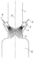
図1は、円筒状の反応ゾーン1を示しており、その中で気体混合物は頂部側から底部側へ破線9に沿って流れる。反応ゾーン1を出ると、気体混合物は同様に円筒状のクエンチングゾーン5の中へ流入する。クエンチングゾーン5の中には2つのノズルヘッド3が設けられており、各ノズルヘッド3はそれぞれ2個のノズル4を備えており、2個のノズル4は互いに直径方向に向い合って配置されている。クエンチング液体はパイプ2を通してノズルヘッド3へ供給される。ノズル4及びノズルヘッド3は、クエンチング液体の(破線8で示す)流れ方向と気体ストリームの流れ方向9とが互いに好ましくは0゜〜50゜、より好ましくは20゜〜35゜の角度をなすように配置されている。従って、高温の気体混合物は、それより低温のノズル及びノズルヘッドとは接触しない。クエンチングゾーン5において、反応気体の冷却は、噴霧された液体の気化によって行われる。残りの液体及び冷却された反応気体は、クエンチングゾーンの下流側に配されている液体収集コンテナ6の中に送られる。コンテナ6は、ポンプ−タンクとして、及び気体と液体との分離装置として同時に機能することができる。
FIG. 1 shows a cylindrical reaction zone 1 in which the gas mixture flows along the dashed line 9 from the top to the bottom. Upon leaving reaction zone 1, the gas mixture flows into a similarly
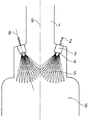
図2に示すクエンチングゾーンの態様は、基本的に図1に示す態様に対応する。従って、図2において図1と同じ符号で示される部材は、図1の部材と同じか又は同様の部材である。図2に示す態様は、クエンチングゾーン5が管状の反応装置1よりも大きい直径を有する点で、図1の態様とは異なっている。
態 様 The mode of the quenching zone shown in FIG. 2 basically corresponds to the mode shown in FIG. Therefore, the members denoted by the same reference numerals in FIG. 2 as those in FIG. 1 are the same as or similar to the members in FIG. The embodiment shown in FIG. 2 differs from the embodiment of FIG. 1 in that the
直径260mmを有し垂直方向に配された管状の反応装置から、温度400℃及び圧力1000〜1800ミリバールの条件にて、6700kg/時のイソホロンジイソシアネート、塩化水素及び過剰のホスゲンの気体混合物を、その下流側に設けられている直径510mmのクエンチングゾーンに18m/秒の流量で流入させた。反応ゾーンからクエンチングゾーンへかけて拡開する(又は拡がる)管状のゾーンは、垂直に対して75゜の角度をなすように構成されていた。拡開する部分には、4個の独立したノズルが外周に沿って等間隔に配置されており、イソホロンジイソシアネートのモノクロロベンゼン溶液(体積比20:80)を120℃の温度で130×103kg/時にて噴霧した。クエンチング液体の流れ方向は、気体混合物の流れ方向に対して35゜であった。ノズルの噴霧テーパ角度は30゜であった。反応気体の冷却はクエンチングゾーン内で行った。溶液中に溶解している凝縮性成分及び冷却の目的に必要な量のモノクロロベンゼンが気化した。液体/気体混合物を分離装置に通した。0.8〜1.3秒の接触時間の後、分離装置内に集められた濃厚なイソホロンジイソシアネートのモノクロロベンゼン溶液の温度は140℃であった。分離装置から流出する気体の温度は145℃であった。 At a temperature of 400 ° C. and a pressure of 1000 to 1800 mbar, 6700 kg / h of a gas mixture of isophorone diisocyanate, hydrogen chloride and excess phosgene are obtained from a vertically arranged tubular reactor having a diameter of 260 mm. It flowed at a flow rate of 18 m / sec into a quenching zone having a diameter of 510 mm provided on the downstream side. The tubular zone expanding (or expanding) from the reaction zone to the quenching zone was configured to form a 75 ° angle to vertical. In the expanding portion, four independent nozzles are arranged at equal intervals along the outer circumference, and a monochlorobenzene solution of isophorone diisocyanate (volume ratio: 20:80) is heated to 130 × 10 3 kg at a temperature of 120 ° C. / Time sprayed. The flow direction of the quenching liquid was 35 ° to the flow direction of the gas mixture. The spray taper angle of the nozzle was 30 °. Cooling of the reaction gas was performed in the quenching zone. The condensable components dissolved in the solution and the required amount of monochlorobenzene for cooling purposes were vaporized. The liquid / gas mixture was passed through a separator. After a contact time of 0.8 to 1.3 seconds, the temperature of the concentrated isophorone diisocyanate monochlorobenzene solution collected in the separator was 140 ° C. The temperature of the gas flowing out of the separator was 145 ° C.
以上、本発明について説明するために詳細に記載したが、詳細な事項は説明の目的のものであること、並びに、特許請求の範囲に規定する事項以外に、本発明の範囲及び精神から離れることなく、当業者は本発明に変更を加えることができるということに注意されたい。 As described above, the present invention has been described in detail for the purpose of explanation. However, the detailed matter is for the purpose of explanation, and departs from the scope and spirit of the invention other than the matters defined in the claims. Rather, it is noted that those skilled in the art can make changes to the invention.
1 反応ゾーン、 2パイプ、 3 ノズルヘッド、 4 ノズル、 5 クエンチングゾーン、 6 液体収集コンテナ、 8 クエンチング液体の流れ方向を示す破線 9 気体混合物の流れ方向を示す破線。
1 reaction zone, 2 pipes, 3 nozzle head, 4 nozzles, 5 quenching zone, 6 liquid collection container, 8 dashed line indicating flow direction of quenching liquid 9 dashed line indicating flow direction of gas mixture
Claims (11)
The method of claim 1, wherein the quenching liquid is selected from the group consisting of monochlorobenzene and o-dichlorobenzene.
Applications Claiming Priority (1)
| Application Number | Priority Date | Filing Date | Title |
|---|---|---|---|
| DE10245704A DE10245704A1 (en) | 2002-09-30 | 2002-09-30 | Process for quenching a gaseous reaction mixture in the gas phase phosgenation of diamines |
Publications (3)
| Publication Number | Publication Date |
|---|---|
| JP2004123745A true JP2004123745A (en) | 2004-04-22 |
| JP2004123745A5 JP2004123745A5 (en) | 2006-11-16 |
| JP4486800B2 JP4486800B2 (en) | 2010-06-23 |
Family
ID=31969722
Family Applications (1)
| Application Number | Title | Priority Date | Filing Date |
|---|---|---|---|
| JP2003340037A Expired - Lifetime JP4486800B2 (en) | 2002-09-30 | 2003-09-30 | Method for quenching gaseous reaction mixtures during gas phase phosgenation of diamines |
Country Status (9)
| Country | Link |
|---|---|
| US (1) | US6800781B2 (en) |
| EP (1) | EP1403248B1 (en) |
| JP (1) | JP4486800B2 (en) |
| CN (1) | CN1318394C (en) |
| AT (1) | ATE327217T1 (en) |
| CA (1) | CA2442467C (en) |
| DE (2) | DE10245704A1 (en) |
| ES (1) | ES2265543T3 (en) |
| MX (1) | MXPA03008808A (en) |
Cited By (14)
| Publication number | Priority date | Publication date | Assignee | Title |
|---|---|---|---|---|
| JP2008150372A (en) * | 2006-12-13 | 2008-07-03 | Bayer Materialscience Ag | Process for producing isocyanates in the gas phase |
| JP2010508374A (en) * | 2006-11-07 | 2010-03-18 | ビーエーエスエフ ソシエタス・ヨーロピア | Isocyanate production method |
| JP2010508375A (en) * | 2006-11-07 | 2010-03-18 | ビーエーエスエフ ソシエタス・ヨーロピア | Isocyanate production method |
| JP2010138171A (en) * | 2008-12-11 | 2010-06-24 | Bayer Materialscience Ag | Method for producing isocyanate in gas phase |
| JP2010536803A (en) * | 2007-08-21 | 2010-12-02 | 寧波萬華聚▲あんじ▼有限公司 | JET REACTION APPARATUS PROVIDED WITH FLOW DUCT AND METHOD FOR PRODUCING ISocyanates USING JET REACTION APPARATUS HAVING FLOW DUCT |
| JP2012505850A (en) * | 2008-10-15 | 2012-03-08 | ビーエーエスエフ ソシエタス・ヨーロピア | Isocyanate production method |
| JP2012508212A (en) * | 2008-11-07 | 2012-04-05 | ビーエーエスエフ ソシエタス・ヨーロピア | Isocyanate production method |
| JP2012510495A (en) * | 2008-12-03 | 2012-05-10 | ビーエーエスエフ ソシエタス・ヨーロピア | Isocyanate production method |
| JP2012523389A (en) * | 2009-04-08 | 2012-10-04 | ビーエーエスエフ ソシエタス・ヨーロピア | Isocyanate production method |
| JP2013512273A (en) * | 2009-12-01 | 2013-04-11 | ビーエーエスエフ ソシエタス・ヨーロピア | Method for producing isocyanate by thermal cleavage of carbamate |
| JP2013522261A (en) * | 2010-03-18 | 2013-06-13 | ビーエーエスエフ ソシエタス・ヨーロピア | Isocyanate production method |
| JP2013173784A (en) * | 2006-01-13 | 2013-09-05 | Basf Se | Method for producing isocyanate |
| JP2014520086A (en) * | 2011-05-24 | 2014-08-21 | ビーエーエスエフ ソシエタス・ヨーロピア | Method for producing polyisocyanate from biomass |
| JP2016529239A (en) * | 2013-07-26 | 2016-09-23 | コベストロ、ドイチュラント、アクチエンゲゼルシャフトCovestro Deutschland Ag | Isocyanate production method |
Families Citing this family (47)
| Publication number | Priority date | Publication date | Assignee | Title |
|---|---|---|---|---|
| DE102004030164A1 (en) * | 2004-06-22 | 2006-01-19 | Basf Ag | Process for the preparation of isocyanates |
| DE102005036870A1 (en) * | 2005-08-02 | 2007-02-08 | Bayer Materialscience Ag | Process for gas phase phosgenation |
| DE102005037328A1 (en) | 2005-08-04 | 2007-02-08 | Basf Ag | Process for the preparation of isocyanates |
| US7504533B2 (en) * | 2006-04-24 | 2009-03-17 | Bayer Materialscience Llc | Process for the production of isocyanates |
| CN101495643A (en) | 2006-08-01 | 2009-07-29 | 巴斯夫欧洲公司 | Process for preparing pentamethylene 1,5-diisocyanate |
| CN100427463C (en) * | 2006-09-14 | 2008-10-22 | 宁波万华聚氨酯有限公司 | Apparatus for preparing high-boiling-point heat-sensitive substance, and its application method |
| JP2010512364A (en) * | 2006-12-11 | 2010-04-22 | ビーエーエスエフ ソシエタス・ヨーロピア | Isocyanate production method |
| DE102006058633A1 (en) | 2006-12-13 | 2008-06-19 | Bayer Materialscience Ag | Process for the preparation of isocyanates in the gas phase |
| ES2558857T3 (en) | 2007-01-17 | 2016-02-09 | Basf Se | Procedure for the preparation of isocyanates |
| EP2028178A1 (en) | 2007-08-22 | 2009-02-25 | Bayer MaterialScience AG | Manufacture of isocyanates with low chlorine content |
| JP2010536911A (en) | 2007-08-30 | 2010-12-02 | ビーエーエスエフ ソシエタス・ヨーロピア | Isocyanate production method |
| JP5535912B2 (en) * | 2007-09-04 | 2014-07-02 | シエル・インターナシヨネイル・リサーチ・マーチヤツピイ・ベー・ウイ | Quenching vessel |
| WO2009037179A1 (en) | 2007-09-19 | 2009-03-26 | Basf Se | Process for preparing isocyanates |
| ES2582173T3 (en) | 2007-11-14 | 2016-09-09 | Covestro Deutschland Ag | Preparation of light colored isocyanates |
| DE102007056511A1 (en) | 2007-11-22 | 2009-05-28 | Bayer Materialscience Ag | Process for the preparation of aromatic diisocyanates in the gas phase |
| US7846226B2 (en) | 2008-02-13 | 2010-12-07 | General Electric Company | Apparatus for cooling and scrubbing a flow of syngas and method of assembling |
| DE102008009761A1 (en) | 2008-02-19 | 2009-08-27 | Bayer Materialscience Ag | Process for the preparation of isocyanates |
| EP2128127A1 (en) * | 2008-05-31 | 2009-12-02 | Bayer MaterialScience AG | Separating ammonium chloride from the gas phase |
| ES2440748T3 (en) * | 2008-12-03 | 2014-01-30 | Bayer Intellectual Property Gmbh | Procedure for the modification of diisocyanates |
| DE102008063728A1 (en) | 2008-12-18 | 2010-06-24 | Bayer Materialscience Ag | Process for the preparation of isocyanates in the gas phase |
| DE102009032413A1 (en) | 2009-07-09 | 2011-01-13 | Bayer Materialscience Ag | Process for the preparation of isocyanates |
| DE102009032414A1 (en) | 2009-07-09 | 2011-01-13 | Bayer Materialscience Ag | Process for the preparation of isocyanates in the gas phase |
| DE102009033639A1 (en) | 2009-07-17 | 2011-01-20 | Bayer Materialscience Ag | Procedures for the preparation of isocyanates in the gas phase |
| US8981145B2 (en) | 2010-03-18 | 2015-03-17 | Basf Se | Process for preparing isocyanates |
| DE102010019342A1 (en) | 2010-05-05 | 2011-11-10 | Bayer Materialscience Ag | Process for the preparation of isocyanates in the gas phase |
| PL214498B1 (en) | 2010-12-10 | 2013-08-30 | Inst Chemii Przemyslowej Im Prof Ignacego Moscickiego | Method for isolating the products of toluilenodiamine (TDA) phosgenation in the gas phase during preparation of toluilenodiizocyanate (TDI) |
| US8933262B2 (en) | 2011-05-24 | 2015-01-13 | Basf Se | Process for preparing polyisocyanates from biomass |
| WO2014122180A1 (en) | 2013-02-08 | 2014-08-14 | Bayer Materialscience Ag | Method for separating an isocyanate, which was produced by phosgenating a primary amine in the gas phase, from the gaseous raw product of the phosgenation |
| US9567268B2 (en) | 2013-06-28 | 2017-02-14 | Uop Llc | High temperature quench system and process |
| US9328038B2 (en) * | 2013-06-28 | 2016-05-03 | Uop Llc | High temperature quench system and process |
| EP3013469B1 (en) * | 2013-06-28 | 2020-06-03 | Uop Llc | High temperature quench system and process |
| US10294198B2 (en) | 2014-04-11 | 2019-05-21 | Covestro Deutschland Ag | Method for producing xylylene diisocyanates in the gaseous phase |
| KR102733348B1 (en) | 2015-06-12 | 2024-11-25 | 코베스트로 도이칠란트 아게 | Gas phase production method of diisocyanate |
| CN107848960B (en) | 2015-07-16 | 2020-09-22 | 科思创德国股份有限公司 | Process for the preparation of isocyanates |
| CN105509507B (en) * | 2016-01-07 | 2017-07-14 | 甘肃银光聚银化工有限公司 | A kind of loop spray cooler and using its method to isocyanates gas fast cooling |
| US10703713B2 (en) | 2016-12-21 | 2020-07-07 | Covestro Deutschland Ag | Process for preparing an isocyanate |
| US10919845B2 (en) | 2017-04-03 | 2021-02-16 | Covestro Deutschland Ag | Cleaning device for gas flows from isocyanate production |
| CN110914236B (en) | 2017-06-08 | 2023-01-31 | 科思创德国股份有限公司 | Method for producing isocyanates |
| EP3634947B1 (en) | 2017-06-08 | 2022-09-07 | Covestro Intellectual Property GmbH & Co. KG | Method for the production of isocyanates in the gasphase |
| WO2019048644A1 (en) | 2017-09-11 | 2019-03-14 | Covestro Deutschland Ag | Process for quenching a gaseous reaction mixture obtained in the gas phase phosgenation of diamines |
| US10626084B2 (en) | 2018-08-03 | 2020-04-21 | Covestro Llc | Method for producing two isocyanates |
| JP2022547814A (en) | 2019-09-17 | 2022-11-16 | コベストロ、ドイチュラント、アクチエンゲゼルシャフト | Method for producing isocyanate |
| PT4247784T (en) | 2020-11-23 | 2025-03-14 | Basf Se | Process for producing isocyanates |
| EP4104922A1 (en) | 2021-06-14 | 2022-12-21 | Covestro Deutschland AG | Reactor and process for preparing isocyanates |
| WO2022263320A1 (en) | 2021-06-14 | 2022-12-22 | Covestro Deutschland Ag | Reactor and process for preparing isocyanates |
| EP4480944A1 (en) | 2023-06-20 | 2024-12-25 | Covestro Deutschland AG | Process for the preparation of aliphatic diisocyanates in the gas phase |
| WO2025036896A1 (en) | 2023-08-15 | 2025-02-20 | Covestro Deutschland Ag | Method for providing a granulate suitable for combustion, granulate suitable for combustion, and use of same as a fuel |
Family Cites Families (6)
| Publication number | Priority date | Publication date | Assignee | Title |
|---|---|---|---|---|
| DE3714439A1 (en) * | 1987-04-30 | 1988-11-10 | Bayer Ag | METHOD FOR PRODUCING (CYCLO) ALIPHATIC DIISOCYANATES |
| DE4217019A1 (en) * | 1992-05-22 | 1993-11-25 | Bayer Ag | Process for the preparation of aromatic diisocyanates |
| FR2697017B1 (en) * | 1992-10-16 | 1995-01-06 | Rhone Poulenc Chimie | Process for the preparation of compounds of the aromatic isocyanate type in the gas phase. |
| FR2723585B1 (en) * | 1994-08-12 | 1996-09-27 | Rhone Poulenc Chimie | PROCESS FOR THE PREPARATION OF AROMATIC POLYISOCYANATE COMPOUNDS IN THE GASEOUS PHASE. |
| DE19523385A1 (en) * | 1995-06-23 | 1997-01-09 | Bayer Ag | Process for the preparation of triisocyanates |
| CN1194962C (en) * | 2000-12-29 | 2005-03-30 | K·S·T·公司 | Method and apparatus for continuously preparing tolylene diisocyanate |
-
2002
- 2002-09-30 DE DE10245704A patent/DE10245704A1/en not_active Withdrawn
-
2003
- 2003-09-17 ES ES03020535T patent/ES2265543T3/en not_active Expired - Lifetime
- 2003-09-17 AT AT03020535T patent/ATE327217T1/en not_active IP Right Cessation
- 2003-09-17 EP EP03020535A patent/EP1403248B1/en not_active Expired - Lifetime
- 2003-09-17 DE DE50303448T patent/DE50303448D1/en not_active Expired - Lifetime
- 2003-09-25 CA CA2442467A patent/CA2442467C/en not_active Expired - Fee Related
- 2003-09-25 US US10/670,409 patent/US6800781B2/en not_active Expired - Lifetime
- 2003-09-26 MX MXPA03008808A patent/MXPA03008808A/en active IP Right Grant
- 2003-09-30 CN CNB03125506XA patent/CN1318394C/en not_active Expired - Lifetime
- 2003-09-30 JP JP2003340037A patent/JP4486800B2/en not_active Expired - Lifetime
Cited By (15)
| Publication number | Priority date | Publication date | Assignee | Title |
|---|---|---|---|---|
| JP2013173784A (en) * | 2006-01-13 | 2013-09-05 | Basf Se | Method for producing isocyanate |
| JP2010508374A (en) * | 2006-11-07 | 2010-03-18 | ビーエーエスエフ ソシエタス・ヨーロピア | Isocyanate production method |
| JP2010508375A (en) * | 2006-11-07 | 2010-03-18 | ビーエーエスエフ ソシエタス・ヨーロピア | Isocyanate production method |
| JP2008150372A (en) * | 2006-12-13 | 2008-07-03 | Bayer Materialscience Ag | Process for producing isocyanates in the gas phase |
| KR101433943B1 (en) | 2006-12-13 | 2014-08-25 | 바이엘 머티리얼사이언스 아게 | Process for the preparation of isocyanates in the gas phase |
| JP2010536803A (en) * | 2007-08-21 | 2010-12-02 | 寧波萬華聚▲あんじ▼有限公司 | JET REACTION APPARATUS PROVIDED WITH FLOW DUCT AND METHOD FOR PRODUCING ISocyanates USING JET REACTION APPARATUS HAVING FLOW DUCT |
| JP2012505850A (en) * | 2008-10-15 | 2012-03-08 | ビーエーエスエフ ソシエタス・ヨーロピア | Isocyanate production method |
| JP2012508212A (en) * | 2008-11-07 | 2012-04-05 | ビーエーエスエフ ソシエタス・ヨーロピア | Isocyanate production method |
| JP2012510495A (en) * | 2008-12-03 | 2012-05-10 | ビーエーエスエフ ソシエタス・ヨーロピア | Isocyanate production method |
| JP2010138171A (en) * | 2008-12-11 | 2010-06-24 | Bayer Materialscience Ag | Method for producing isocyanate in gas phase |
| JP2012523389A (en) * | 2009-04-08 | 2012-10-04 | ビーエーエスエフ ソシエタス・ヨーロピア | Isocyanate production method |
| JP2013512273A (en) * | 2009-12-01 | 2013-04-11 | ビーエーエスエフ ソシエタス・ヨーロピア | Method for producing isocyanate by thermal cleavage of carbamate |
| JP2013522261A (en) * | 2010-03-18 | 2013-06-13 | ビーエーエスエフ ソシエタス・ヨーロピア | Isocyanate production method |
| JP2014520086A (en) * | 2011-05-24 | 2014-08-21 | ビーエーエスエフ ソシエタス・ヨーロピア | Method for producing polyisocyanate from biomass |
| JP2016529239A (en) * | 2013-07-26 | 2016-09-23 | コベストロ、ドイチュラント、アクチエンゲゼルシャフトCovestro Deutschland Ag | Isocyanate production method |
Also Published As
| Publication number | Publication date |
|---|---|
| EP1403248A1 (en) | 2004-03-31 |
| ES2265543T3 (en) | 2007-02-16 |
| MXPA03008808A (en) | 2004-04-15 |
| ATE327217T1 (en) | 2006-06-15 |
| US6800781B2 (en) | 2004-10-05 |
| CA2442467C (en) | 2011-04-12 |
| US20040068137A1 (en) | 2004-04-08 |
| HK1065998A1 (en) | 2005-03-11 |
| CN1496977A (en) | 2004-05-19 |
| CA2442467A1 (en) | 2004-03-30 |
| CN1318394C (en) | 2007-05-30 |
| JP4486800B2 (en) | 2010-06-23 |
| DE10245704A1 (en) | 2004-04-01 |
| EP1403248B1 (en) | 2006-05-24 |
| DE50303448D1 (en) | 2006-06-29 |
Similar Documents
| Publication | Publication Date | Title |
|---|---|---|
| JP2004123745A (en) | Method for quenching gaseous reaction mixture in gaseous phase phosgenation of diamine | |
| RU2464258C2 (en) | Method of producing isocyanates | |
| RU2460722C2 (en) | Method or producing isocyanates | |
| RU2440333C2 (en) | Method of producing (cyclo)aliphatic and aromatic diisocyanates via phosgenation of (cyclo)aliphatic and aromatic diamines in gas phase | |
| JP5574684B2 (en) | Process for producing isocyanates in the gas phase | |
| US20030114705A1 (en) | Process for the production of (poly)isocyanates in the gas phase | |
| JP5699128B2 (en) | Isocyanate production method | |
| US20110124907A1 (en) | Jet reactor with flow ducts and process for preparing isocyanates using it | |
| KR20040058335A (en) | Production of isocyanates in the gaseous phase | |
| JP5787908B2 (en) | Isocyanate production method | |
| JP6893927B2 (en) | Isocyanate production method | |
| US20220213027A1 (en) | Method and device for preparing diisocyanate | |
| CN111094240B (en) | Process for quenching a gaseous reaction mixture obtained in the gas-phase phosgenation of diamines | |
| KR20160034908A (en) | Method for producing isocyanates | |
| US8981145B2 (en) | Process for preparing isocyanates | |
| HK1065998B (en) | A process for quenching a gaseous reaction mixture during the gas phase phosgenation of diamines | |
| HK1118532A (en) | Process for the preparation of isocyanates in the gas phase |
Legal Events
| Date | Code | Title | Description |
|---|---|---|---|
| A521 | Request for written amendment filed |
Free format text: JAPANESE INTERMEDIATE CODE: A523 Effective date: 20060928 |
|
| A621 | Written request for application examination |
Free format text: JAPANESE INTERMEDIATE CODE: A621 Effective date: 20060928 |
|
| RD02 | Notification of acceptance of power of attorney |
Free format text: JAPANESE INTERMEDIATE CODE: A7422 Effective date: 20060928 |
|
| A131 | Notification of reasons for refusal |
Free format text: JAPANESE INTERMEDIATE CODE: A131 Effective date: 20090901 |
|
| A601 | Written request for extension of time |
Free format text: JAPANESE INTERMEDIATE CODE: A601 Effective date: 20091130 |
|
| A602 | Written permission of extension of time |
Free format text: JAPANESE INTERMEDIATE CODE: A602 Effective date: 20091203 |
|
| A601 | Written request for extension of time |
Free format text: JAPANESE INTERMEDIATE CODE: A601 Effective date: 20100104 |
|
| A602 | Written permission of extension of time |
Free format text: JAPANESE INTERMEDIATE CODE: A602 Effective date: 20100107 |
|
| A521 | Request for written amendment filed |
Free format text: JAPANESE INTERMEDIATE CODE: A523 Effective date: 20100129 |
|
| TRDD | Decision of grant or rejection written | ||
| A01 | Written decision to grant a patent or to grant a registration (utility model) |
Free format text: JAPANESE INTERMEDIATE CODE: A01 Effective date: 20100302 |
|
| A01 | Written decision to grant a patent or to grant a registration (utility model) |
Free format text: JAPANESE INTERMEDIATE CODE: A01 |
|
| A61 | First payment of annual fees (during grant procedure) |
Free format text: JAPANESE INTERMEDIATE CODE: A61 Effective date: 20100329 |
|
| R150 | Certificate of patent or registration of utility model |
Ref document number: 4486800 Country of ref document: JP Free format text: JAPANESE INTERMEDIATE CODE: R150 Free format text: JAPANESE INTERMEDIATE CODE: R150 |
|
| FPAY | Renewal fee payment (event date is renewal date of database) |
Free format text: PAYMENT UNTIL: 20130402 Year of fee payment: 3 |
|
| FPAY | Renewal fee payment (event date is renewal date of database) |
Free format text: PAYMENT UNTIL: 20130402 Year of fee payment: 3 |
|
| FPAY | Renewal fee payment (event date is renewal date of database) |
Free format text: PAYMENT UNTIL: 20140402 Year of fee payment: 4 |
|
| R250 | Receipt of annual fees |
Free format text: JAPANESE INTERMEDIATE CODE: R250 |
|
| R250 | Receipt of annual fees |
Free format text: JAPANESE INTERMEDIATE CODE: R250 |
|
| R250 | Receipt of annual fees |
Free format text: JAPANESE INTERMEDIATE CODE: R250 |
|
| R250 | Receipt of annual fees |
Free format text: JAPANESE INTERMEDIATE CODE: R250 |
|
| R250 | Receipt of annual fees |
Free format text: JAPANESE INTERMEDIATE CODE: R250 |
|
| R250 | Receipt of annual fees |
Free format text: JAPANESE INTERMEDIATE CODE: R250 |
|
| R250 | Receipt of annual fees |
Free format text: JAPANESE INTERMEDIATE CODE: R250 |
|
| R250 | Receipt of annual fees |
Free format text: JAPANESE INTERMEDIATE CODE: R250 |