JP2004122984A - Seat for vehicle - Google Patents
Seat for vehicle Download PDFInfo
- Publication number
- JP2004122984A JP2004122984A JP2002291398A JP2002291398A JP2004122984A JP 2004122984 A JP2004122984 A JP 2004122984A JP 2002291398 A JP2002291398 A JP 2002291398A JP 2002291398 A JP2002291398 A JP 2002291398A JP 2004122984 A JP2004122984 A JP 2004122984A
- Authority
- JP
- Japan
- Prior art keywords
- backrest
- extension
- vehicle seat
- depth
- seat
- Prior art date
- Legal status (The legal status is an assumption and is not a legal conclusion. Google has not performed a legal analysis and makes no representation as to the accuracy of the status listed.)
- Granted
Links
Images


Abstract
Description
【0001】
【発明の属する技術分野】
本発明は、バス、鉄道車輌、航空機、船舶その他の各種乗物に設置される乗物用座席に関するものである。
【0002】
【従来の技術】
図16に示すように、従来の多くの乗物用座席80においては、背当81の背面側に設けられたテーブル82が、収納時には背当81の背面に略平行に近接して収納され、使用時には前端は背当81の背面から離間して(離間しないものもある)全体は略水平となるまで回動されるように支持されている。(例えば、特許文献1、特許文献2、特許文献3、特許文献4参照)この回動の中心83はテーブル82の前端付近にあり(回動の中心83からテーブル82の前端までは高々数cmである。) 、従って、テーブル82の奥行はその大半が回動の中心83からテーブル82の前端までで決まる。
【0003】
【特許文献1】
実公平6−9893号公報
【特許文献2】
登録実用新案第2547750号公報
【特許文献3】
実公昭63−28675号公報
【特許文献4】
特開平6−32166号公報
【特許文献5】
実開昭58−58949号公報
【0004】
【発明が解決しようとする課題】
(1)テーブル82は弁当、飲料容器、本、書類、ノートパソコン等の様々な物を置くために使用される。ところが、従来のテーブル82の寸法は、幅についてはさておくとして、奥行については、前後の座席間距離とテーブルの支持機構との関係からくる制約や、テーブルを収納する背当の設計上の制限により、大きく取ることが難しいという問題があった。このため、奥行きの大きい物を置くと、テーブル82の奥行が不足して、置いた物が不安定になることがあった。
【0005】
ところで、使用時の状態を図17(a−1)、収納時の状態を図17(a−2)に示すように、前記テーブル82を前半部82aと後半部82bとに分割形成し、収納時には前者の上に後者が重なり、使用時には前者に対して後者が上面面一に展開するように、両者82a,82bを折り畳み可能に軸着したものもある(例えば、特許文献1参照)。しかし、この折り畳み構造は、収納時のテーブルをコンパクト化して、前述したテーブルを収納する背当の設計上の制限を回避するためのものであって、展開したときのテーブル82の奥行を拡張するためのものではないため、上記問題を解消しない。もっとも、本発明者は、この前半部82aと後半部82bの奥行をそれぞれ少し大きくすれば、展開したときのテーブル82の奥行を拡張できると考えたが、そうするとテーブル82の後端が使用者に接近しすぎ、次の(2)で述べるような問題が生じるので採用しなかった。
【0006】
なお、本発明には背当の背面の凹部を構成要素としているものがあるので、念のために凹部に関する従来技術について触れると、従来においても背当の背面に凹部を設けたものは知られている(例えば、特許文献5参照)。ところが、従来の凹部は、もっぱら小物を収納するための凹部であって、テーブルとは無関係に独立して存在していた。よって、かかる従来技術は本発明とは無関係である。
【0007】
(2)前述のとおり、使用時にテーブル82を略水平に回動させるだけでなく、テーブル82の前端を背当81の背面から離間させるのは、テーブル82を使用者に接近させて使用しやすくするためである。さらに、非スライド時の状態を図17(b−1)、スライド時の状態を図17(b−2)に示すように、使用時のテーブル82を前記回動直後の基準位置からそれより後方位置にスライドさせて、テーブル82をより使用者に接近させるものもあるほどである(例えば、特許文献2参照)。
【0008】
ところが、航空機のエコノミークラスに代表されるように前後の座席間ピッチが小さい場合や、使用者の体格が大きい場合等には、上記のようにテーブル82を使用者に接近させると、接近しすぎて却って使用しにくいことがあることが分かってきた。
【0009】
そこで、本発明の第一の目的は、奥行の大きな物も安定して置くことができ、また、使用者に接近しすぎず使用しやすいテーブルを備えた乗物用座席を提供することにある。本発明の第二の目的は、使用者に接近しすぎず使用しやすいテーブルを備えた乗物用座席を提供することにある。
【0010】
【課題を解決するための手段】
(1)背当の背面側に設けられたテーブルが、収納時には背当の背面に略平行に近接して収納され、使用時には前端は背当の背面から離間することなく全体は略水平となるまで回動されるように支持された乗物用座席において、背当の背面に使用時のテーブルのテーブル面と略同一高さレベルで略水平に延びる拡張テーブル面を備えた拡張用凹部を形成し、使用時のテーブル面に拡張テーブル面を略連続させることによりテーブル奥行を拡張可能としたことを特徴とする乗物用座席。
【0011】
同手段(1)において、拡張テーブル面を略水平とするのは、いうまでもなく使用時のテーブル面が水平だからである。背当がリクライニングしないものである場合は、拡張テーブル面を水平に形成すればよい。背当がリクライニングするものである場合は、そのリクライニング角度に伴って拡張テーブル面の角度も変わるので、拡張テーブル面を、リクライニング角度範囲内のどこか一点(例えば、未リクライニング点、リクライニング中点又は最大リクライニング点)で水平となり、同角度範囲内の他点では多少角度の付いた略水平となるように、形成すればよい。
【0012】
拡張テーブル面の奥行は、特に限定されないが、背当の厚さの1/3〜9/10程度が好ましい。背当の正面側にクッション材を設ける余地を残しながら取りうる効果的な奥行と考えられるからである。拡張テーブル面の幅は、特に限定されないが、テーブルの幅と同程度以上であることが好ましく、上限は当然に背当の幅で制約される。拡張用凹部の高さは、特に限定されないが、例えば弁当箱、本、ノートパソコン等が入り込めるようにするためには50mm以上(高さが変化するときは最低部で)が好ましく、100mm以上がさらに好ましい。また、拡張用凹部の高さは、深部よりも開口部で高く変化していることが好ましい。また、拡張用凹部は収納時のテーブルで塞がれるようになっていることが好ましく、その場合、拡張用凹部の高さの上限は当然にテーブルの奥行で制限される。
【0013】
(2)背当の背面側に設けられたテーブルが、収納時には背当の背面に略平行に近接して収納され、使用時には前端は背当の背面から離間することなく又は離間して全体は略水平となるまで回動されるように支持された乗物用座席において、使用時のテーブルの前端側に回動の中心から前方へ略水平に延びる拡張テーブル面を設けることによりテーブル奥行を拡張可能とし、テーブルの後端から中心までの奥行分に対して中心から拡張テーブル面の前端までの奥行分を少なくとも1/4倍としたことを特徴とする乗物用座席。
【0014】
前記従来例でも回動の中心から前方へ数cm出てはいたが、これは軸の配設上の問題であってテーブルの拡張が目的ではない。本発明では実質的にテーブルを拡張すべく拡張テーブル面の奥行分の下限を「少なくとも1/4倍」とした。一方、拡張テーブル面の奥行分の上限は、テーブルの後端のはね上がり防止手段がある場合には、特に制限されない。テーブルの後端のはね上がり防止手段がないときには、背当までの距離又は背当に設けられた逃がし用凹部までの距離で制限され、1倍以上だとその自重によるモーメントで拡張テーブルの前端が下がってテーブルの後端がはね上がるので、1倍未満にする。また、1倍未満でも拡張テーブル側に物を置いたときには、同様に拡張テーブルの前端が下がるので、好ましくは1/2倍以下にする。
同手段(2)における拡張テーブル面は、次の態様(a)(b)に大別できる。
【0015】
(a)拡張テーブル面が、テーブルと一体的に形成されたテーブル拡張部分の上面である態様。テーブルとテーブル拡張部分とは、同じ材料で連続するように一体形成されたものでもよいし、同じ材料又は異なる材料で形成されたものを一体化したものでもよい。
【0016】
(b)拡張テーブル面が、テーブルと別体に形成され連結された拡張テーブルの上面である態様。連結の仕方は、特に限定されないが、次の態様▲1▼▲2▼を例示できる。
▲1▼ 拡張テーブルがテーブルに対し、拡張テーブル面とテーブル面とが面一となる拡張時位置と非面一となる非拡張時位置との間で回動可能に連結される態様。回動の態様は、特に限定されないが、拡張テーブル面とテーブル面とが面一と、拡張テーブル面がテーブル面の上に折り重なる非面一との間で、拡張テーブルがテーブルに対し、回動する態様を例示できる。
▲2▼ 拡張テーブルがテーブルに対し、テーブルから引き出される拡張時位置とテーブルに重なる非拡張時位置との間でスライド可能に連結される態様。
重なり方は、特に限定されないが、拡張テーブルがテーブルの下にもぐりこむ態様、テーブルの上に載る態様、中空のテーブル内に入り込む態様等を例示できる。
【0017】
また、同手段(2)において、使用時のテーブル拡張部分又は拡張テーブルの少なくとも前端部が、背当の背面に形成された逃がし用凹部内に入り込むように構成することもできる。この構成は、背当がリクライニングするものである場合に、背当の背面とテーブル拡張部分又は拡張テーブルの前端との干渉を防ぐためである。また、収納時の拡張テーブルの略全体が、背当の背面に形成された逃がし用凹部内に入り込むように構成することもできる。
【0018】
逃がし用凹部の寸法・形状は、特に限定されず、背当がリクライニングするものである場合には、リクライニングした背当とテーブル拡張部分又は拡張テーブルとが干渉しないように考慮する。逃がし用凹部の高さは、前記拡張用凹部と同様に考えることができる。
【0019】
(3)背当の背面側に設けられたテーブルが、収納時には背当の背面に略平行に近接して収納され、使用時には前端は背当の背面から離間して全体は略水平となるまで回動されるように支持された乗物用座席において、使用時のテーブルを回動直後の基準位置とそれより前方の遠ざけ位置との間でスライド可能に支持することによりテーブル位置を使用者から遠ざけられるようにしたことを特徴とする乗物用座席。
【0020】
同手段(3)において、特に限定されないが、遠ざけ位置を前後方向に複数又は無段に設けて、テーブルを任意の遠ざけ位置に調節可能とすることもできる。
【0021】
【発明の実施の形態】
以下、本発明の物用座席を、図面に基づいて、第一実施形態から第六実施形態までに説明する。なお、実施形態に記す数量は例示であって、適宜変更できる。[第一実施形態]
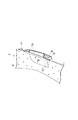
図1〜図3は、本発明をバス用座席1に具体化した第一実施形態を示している。二人掛け用のバス用座席1は、一例として、前脚2及び後脚3に支えられた座枠4と、座枠4にクッション材等を設置して設けられた座部5と、座枠4に約20°リクライニング可能に支持された背当6と、例えば座枠4に支持された肘掛7とを含む基本構成を備えている。
【0022】
本実施形態では、背当6の背面側にはテーブル装置10が付設されている。テーブル装置10は、背当6の下部において座枠4に対して回動可能に結合された一対の支持アーム11と、背当6の上方側の各側部に取り付けられた一対の支持部材12と、支持アーム11と支持部材12との先端間で支持されたテーブル13(幅380mm、奥行180mm、厚さ30mm)とを備えている。このテーブル13は、テーブル13の両側面から外方に突出した回転軸8が支持アーム11の先端に軸支され、回転軸8より前方に並設された支持軸9が支持部材12の先端に軸支されることで支持されている。支持アーム11はバス用座席1のリクライニングによるテーブル面15を水平に保つための調整を行い、回転軸8はその調整を行う際の軸として働いている。支持部材12はテーブル13の前端13aを背当6の背面側に近接するように支持し、支持軸9は収納の際に回動を行う際の軸として働いている。
このように、回転軸8と支持軸9によって、テーブル13の収納時(図1の右側のバス用座席1のテーブル13の態様)には、テーブル13は背当6の背面に略平行に近接して収納される。その際、背当6の背面の上部の略中央部に取り付けられている回転操作式のラッチ14によって、テーブル13が収納位置に保持される。また、テーブル13の使用時(図1の左側のバス用座席1のテーブル13の態様)には、テーブル13の前端13aは背当6の背面から離間することなく全体は略水平となるまで回動できるように支持される。
【0023】
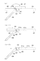
背当6の背面には、拡張用凹部16(幅280mm、奥行40mm、高さ120mm)が形成されている。この拡張用凹部16は使用時のテーブル13のテーブル面15と略同一高さレベルで略水平の拡張テーブル面17を備えており、使用時のテーブル面15に拡張テーブル面17を略連続させることによりテーブル奥行を拡張可能とする。本実施形態においては、バス用座席1のリクライニング角度は例えば20°以内であるので、バス用座席1がリクライニング中点(10°)時に、この拡張テーブル面17がテーブル面15と同様に水平となるように、拡張テーブル面17が形成されている。よって、図2(a)に示すように、バス用座席1の未リクライニング点での拡張テーブル面17のテーブル面15に対する角度は、−10°となる。また、図2(b)に示すように、バス用座席1の最大リクライニング点(20°)での拡張テーブル面17の角度は、+10°となる。このように、バス用座席1のリクライニングに際しても、拡張テーブル面17のテーブル面15に対する角度は、略水平を保つようになっている。
また、図3に示すように、この拡張用凹部16は、テーブル13が背当6の背面に略平行に近接して収納される際には、テーブル13によって塞がれる。
【0024】
上記のように構成された第一実施形態のバス用座席1によれば、拡張用凹部16を形成することで、テーブル自体を拡張せずにテーブル奥行を拡張可能させて、奥行の大きな物も安定して置くことができ、使用しやすいテーブル13とすることができる。
【0025】
[第二実施形態]
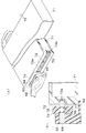
図4〜図7に示す本発明の第二実施形態のバス用座席18は、テーブル13と別体に形成された拡張テーブル22が設けられていることが主として第一実施形態と異なっている。
また、使用時及び収納時の拡張テーブル22(幅270mm、奥行70mm)の略全体が略水平のまま入り込むことができるように、背当6の背面に逃がし用凹部20(幅280mm、奥行60mm、高さ120mm)が形成され、第一実施形態のバス用座席1の拡張用凹部16とは異なった働きをしている。
【0026】
テーブル13を支持している回転軸19と支持軸26は、それぞれがテーブル13内を貫通している1本の軸であり、テーブル13の両側面より突出して、支持アーム11及び支持部材12の先端間に回動可能に軸支されていることが第一実施形態と異なっているがテーブル13に対する働きは第一実施形態と同様である。
【0027】
拡張テーブル22の上面には拡張テーブル面24が設けられており、テーブル13と連結することで、テーブル奥行を拡張可能とする。図4(b)及び図5に示すように、この連結部分の拡張テーブル22側は、拡張テーブル22の後方に拡張テーブル22の両側面が延長された一対の突出部25を備えている。この一対の突出部25には孔27が設けられている。連結部分のテーブル13側には、テーブル13の前端に支持軸26が露出するように一対の逃がし溝28が設けられている。この支持軸26が孔27に回動可能に貫通され、逃がし溝28に突出部25が嵌合して、支持軸26が孔27に回動可能に貫通し、テーブル13と連結される。この支持軸26回りの拡張テーブル22の回動は、テーブル13の使用時と収納時との間で行われる。
拡張テーブル22とテーブル13の連結により、使用時のテーブル13の前端13a側に回動の中心としての支持軸26の前方へ、拡張テーブル22が略水平に延びるている。
【0028】
テーブル13及び拡張テーブル22の使用時は、図6(a)に示すように、拡張テーブル22がテーブル13に設けられている回動止部位29に係止され、拡張テーブル面24とテーブル面15とが略水平の面一である拡張時位置であり、拡張テーブル22の略全体が逃がし用凹部20に入り込んでいる。この逃がし用凹部20の底面21の形状は、図6(b)に示すように、バス用座席18の最大リクライニング点(約20°)で、拡張テーブル面24がテーブル面15と同様に略水平となった際に、逃がし用凹部20の底面21が拡張テーブル22と干渉しないようにする必要がある。そのため、底面21の奥部と口部23とを結ぶ角度は、バス用座席18の最大リクライニング点で略水平となっているので、未リクライニング点で約−20°となっている。
テーブル13及び拡張テーブル22の収納時は、図7に示すように、拡張テーブル22は、略水平のまま逃がし用凹部20内に入り込んでおり、テーブル13のみが背当6の背面に略平行に近接して、拡張テーブル面24とテーブル面15とが非面一となる非拡張時位置で、ラッチ14で留められて収納されている。この際、逃がし用凹部20の背面側の開口部はテーブル13によって塞がれる。また、拡張テーブル22の突出部25が逃がし溝28部分に入り込んでいるため、拡張テーブル22のテーブル13に対する回動が干渉されない。
【0029】
テーブル13の奥行きは180mmであり、テーブル13の後端から支持軸26の中心までは約170mmであるので、支持軸26の中心からテーブル13の前端13aまでは約10mmである。拡張テーブル22の奥行は70mmであるから、テーブル13の後端から支持軸26の中心までの奥行分(約170mm)に対して、支持軸26の中心からテーブル13の前端13aまで(約10mm)と拡張テーブル22の奥行とを加えた支持軸26の中心から拡張テーブル面24の前端までの奥行分(70mm)をあわせた長さ(約80mm)が約1/2倍となっている。
【0030】
上記のように構成された第二実施形態のバス用座席18によれば、使用時には拡張されたテーブル奥行となり、奥行の大きな物も安定して置くことができ、また、使用者に接近しすぎず使用しやすいテーブルを備えたバス用座席18とすることができる。さらに、拡張テーブル22の略全体が入り込むことのできる逃がし用凹部20が形成されていることで、拡張テーブル22がテーブル13と重ならず、非面一で角度を持って収納することができ、背面からは従来のテーブル13のみが収納された場合と同様な状態に収納することができる。
【0031】
次に、第二実施形態の変更例を図8に示す。これは、第二実施形態のバス用座席18とは異なり、支持部材12を備えておらず、テーブル13の使用時にはテーブル13の前端13aは背当6の背面から離間して全体は略水平となるまで回動されるように、支持されているバス用座席である。この場合は、支持軸26aは、テーブル13の両側面に突出せずに、拡張テーブル22を第一実施形態と同様に支持している。回動軸19aは、両側端から外方向に突出するように両側端に形成され、支持アーム11に軸支されている。
【0032】
[第三実施形態]
図9及び図10は、本発明を鉄道車輌の車輌用座席に具体化した第三実施形態を示している。本実施形態の鉄道車輌において、車輌用座席30が2台並設された二人掛け用の座席が鉄道車輌の長手方向に複数列設されている。この車輌用座席30は、一例として基台31と、回転可能な座枠にクッション等を設置して設けられた座部32と、例えば約20°リクライニング可能に支持された背当33と、肘掛34とを含む基本構成を備えている。基台31には、座部32を中心軸の周りで駆動するモータ機構と、基台31に対する座枠のロックを解除する足踏みペダル35と、足載せ台36とが配設されている。
【0033】
本実施形態では、背当33の背面側に設けられたテーブル37(幅340mm、奥行190mm、厚さ20mm)と、テーブル37と一体的に形成されたテーブル拡張部分44(幅340mm、奥行60mm、厚さ20mm)とが設けられている。テーブル拡張部分44の上面である拡張テーブル面43は、使用時のテーブル37の前端側に回動軸40の中心から前方へ略水平に延び、テーブル奥行を拡張可能としている。
一体化されたテーブル37とテーブル拡張部分44とは、車輌用座席30に支持されている一対の支持アーム39の先端間を橋渡ししている回動軸40に、テーブル37の後端より奥行160mm部分で取り付けられており、テーブルの前端を背当の背面側に近接するように支持する支持部材12は用いていないことが、第一実施形態と異なる。
【0034】
支持アーム39には、側面が略ノ状の回動案内孔42が設けられており、この回動案内孔42にテーブル37の回動軸40から前方の両側端面より外方へ突出形成されている回動案内部材41が係合し、テーブル37の回動が案内されている。
このテーブル37及びテーブル拡張部分44の回動は、テーブル37の使用時と収納時との間で行われる。使用時には、テーブル拡張部分44の前端44aは背当33の背面から離間し、回動案内部材41が回動案内孔42の一方端である車輌用座席30側に係止され、テーブル面38及び拡張テーブル面43を略水平に保つことができる。収納時には、テーブル37及びテーブル拡張部分44とが、背当33の背面に略平行に近接して収納され、回動案内部材41が回動案内孔42の他方端に係止され、背当33に取り付けられているラッチ14によって格納位置に保持される。
【0035】
また、テーブル37及びテーブル拡張部分44の使用時に車輌用座席30がリクライニングの態様30aとなった場合、前端44a部分が入り込むことができように、背当33の背面には逃がし用凹部45が形成されている。
【0036】
テーブル37の奥行きは190mmであり、テーブル37の後端から回転軸40の中心までは約160mmであるので、テーブル37部分としては回転軸40から約30mm前方へ突出していることになる。テーブル拡張部分44の奥行は60mmであるから、テーブル37の後端から回転軸40の中心までの奥行分(約160mm)に対して、回転軸40の中心からテーブル37の突出部分(約30mm)とテーブル拡張部分44の奥行き(60mm)とを合わせた回転軸40の中心からテーブル拡張部分44の前端44aまでの奥行分(約90mm)が約1/2倍となっている。
【0037】
上記のように構成された第三実施形態の車輌用座席30によれば、拡張テーブル面43を備えたテーブル拡張部分44を設けることにより、使用時には拡張されたテーブル奥行となり、奥行の大きな物も安定して置くことができ、また、使用者に接近しすぎず使用しやすいテーブルを備えた車輌用座席30とすることができる。さらに、逃がし用凹部45が設けられることで、車輌用座席30がリクライニングしても、使用時のテーブル拡張部分44の前端44aに車輌用座席30が干渉しないようになる。
【0038】
また、テーブル37の後端から前記中心である回動軸40の中心までの奥行に対して、回動軸40の中心から拡張テーブル面43の前端までの奥行きを約1/2倍とすることで、テーブル拡張部分44の前端44aが下がってテーブル37の後端がはね上がりにくく、拡張テーブル44側に物を置いたときでも、テーブル拡張部分44の前端44aが下がることも防止でき、安定してテーブル拡張部分44及びテーブル37を使用できる。
【0039】
[第四実施形態]
図11(a)に示すように、第四実施形態は、車輌用座席30に具体化した第三実施形態とは拡張テーブルの態様のみが異なっており、拡張テーブル面46を上面とするテーブル37と別体に形成された拡張テーブル47(幅340mm、奥行60mm、厚さ20mm)が設けられている。
【0040】
この拡張テーブル47はテーブル37に対し、テーブル面38側で拡張テーブル47が使用時と収納時との間で回動可能となるように、拡張テーブル面46側とテーブル面38側とに渡って、埋め込まれて取り付けられているヒンジ48を用いて連結されている。拡張テーブル47及びテーブル37の使用時には、拡張テーブル面46とテーブル面38とが略水平で面一となる拡張時位置である。拡張テーブル47及びテーブル37の収納時には拡張テーブル面46が、テーブル面38と向かい合って重なり非面一となる非拡張時位置であり、拡張テーブル47がテーブル37と共に背当33の背面に略平行に近接して収納されている。背当33の背面に収納する際に、拡張テーブル47が不用意に回動しないように、拡張テーブル面46とテーブル面38にマグネット等の保持手段を設けるとよい。また、本実施形態のテーブル37は、テーブル面38上に段差が生じるが、拡張テーブル面46がテーブル面38と重なり非面一な状態であってもテーブル37として、使用することができる。
【0041】
[第五実施形態]
図11(b−1)(b−2)に示すように、第五実施形態は、車輌用座席30に具体化した第三実施形態とは、拡張テーブルの態様のみが異なっており、拡張テーブル面49を上面とするテーブル37と別体に形成された拡張テーブル50(幅340mm、奥行80mm、厚さ20mm)が設けられている。
【0042】
この拡張テーブル50はテーブル37に対し、拡張テーブル50とテーブル37は使用時と収納時との間でスライド可能に連結されており、テーブル面38と同方向を向いて、拡張テーブル面49が中空のテーブル37内に入り込む態様である。
図11(b−1)に示すように、使用時には、拡張テーブル50がテーブル37から引き出され、拡張テーブル面49とテーブル面38とが略水平で面一となる拡張時位置である。この際、テーブル37内部の側面に形成されている溝51aを拡張テーブル50の側面から外方に突出している係合部51bが溝51aの前方端で係止することで、拡張テーブル50が引き出され過ぎないようになっている。図11(b−2)に示すように、収納時には、拡張テーブル50とテーブル37とが重なり非面一となる非拡張時位置であり、拡張テーブル50がテーブル37と共に背当33の背面に略平行に近接して収納されているという態様である。
また、拡張テーブル50がテーブル37の内部に収納した状態で、背当33の背面に収納する際に、テーブル拡張部分が飛び出してこないように、支持アーム39の内方に突出した係止部52を設けることが好ましい。
【0043】
上記のように構成された第四実施形態及び第五実施形態の車輌用座席30によれば、第三実施形態の効果に加え、拡張テーブル47、50が取り付けられていて、拡張テーブル面46、49のテーブル奥行が拡張されているにもかかわらず、収納時には、コンパクトに収納することができる。また、テーブル37の拡張が必要な時のみテーブル37を拡張して使用することができ、拡張が必要でない場合には、テーブル37の状態で使用することもできる。
【0044】
[第六実施形態]
図12〜図14は、本発明を航空機用座席53に具体化した第六実施形態を示している。航空機において、航空機用座席53が二台以上並列されていて、航空機の長手方向に複数列設されている。航空機用座席53の列設のピッチは、車輌用座席が1000mm以上のものが多いのに対して、790mm〜900mmと狭いのが通常である。
航空機用座席53は、エコノミークラス、ビジネスクラス及びファーストクラスのいずれの座席にあっても、例えば前脚54及び後脚55に支えられた座枠56と、座枠56にクッション材等を設置して設けられた座部57と、座枠56に約20°のリクライニング可能に支持された背当58と、例えば座枠56に支持された肘掛59とを含む基本構成を備えている。また、第三実施形態と同様に、テーブル61の使用時に航空機用座席53がリクライニングした場合、前端61a部分が入り込むことができように、背当58の背面には逃がし用凹部45が形成されている。
【0045】
本実施形態では、第三実施形態と同様に、背当58の背面側に設けられたテーブル61(幅430mm、奥行240mm、厚さ20mm)は、背当58の背面とは離間して、一対の支持アーム62の間で収納時と使用時との間で回動可能に支持されている。テーブル61は、収納時(図12中の2点鎖線)には背当58の背面に略平行に近接して、支持アーム62の内方に突出して設けられている係止部63に係止して収納され、背当58に設けられたラッチ(図示略)によって収納位置に保持されている。使用時には背当58の背面から離間して全体は略水平となるまで、回動軸64にて回動されるように軸支され、支持アーム62の先端の内方に突出して設けられている回動係止部69に係止してテーブル61の後方が下に下がらないようになっている。また、使用時のテーブル61を回動直後の基準位置とそれより前方の遠ざけ位置との間でスライド可能に支持することにより、テーブル61はテーブル位置を使用者から遠ざけられるようになっている。
【0046】
テーブル61の両側端面65には、両側端面65の長さ方向に延び両側端面65に向けて開口し、略Cの両先端が内側に巻き込まれた断面形状で配された案内溝66が設けられている。支持アーム62に回動軸64を介して取り付けられ、テーブル61の側端面65の長さ方向に沿って延びた係合摺動部材67の摺動部68がこの案内溝66に離間せずに摺動可能に係合させる。
【0047】
上記のように構成された第六実施形態の航空機用座席53によれば、テーブル61を遠ざけ方向へ任意の位置に無段に調節ができるように、スライド可能に支持されていることで、座席のピッチに合わせて、使用者に接近しすぎず使用しやすいテーブルを備えた乗物用座席とすることができる。
【0048】
次に、第六実施形態の変更例を図15に示す。本変更例は、第六実施形態の航空機用座席53の無段スライド可能なテーブル61の代わりに、8段でスライド可能なテーブル71であることだけが異なっている。
テーブル71の両側端面72には、両側端面72の長さ方向に延び、両側端面72に向けて開口した断面略コ状の案内溝73が設けられている。この案内溝73には、両側端面72に向けて開口した半球状の凹み73aが略均等に8個設けられている。支持アーム62には、回動軸64を介して取り付けられている係合摺動部材74のテーブル71方を向いて開口している凹部75に、バネ76を介して取り付けられている先端が半球になっている摺動部位77が設けられている。この摺動部位77をバネ76の付勢力によって案内溝73に離間せずに摺動可能に係合させ、案内溝73の凹み73aで係止させる。
【0049】
上記変更例によれば、第六実施形態の航空機用座席53による効果に加え、テーブル71を遠ざけ方向へ8段に位置調節ができる。
【0050】
なお、本発明は前記実施形態に限定されるものではなく、例えば以下のように、発明の趣旨から逸脱しない範囲で適宜変更して具体化することもできる。
(1)第一実施形態のバス用座席のテーブルを、車輌用座席に用いること又は、第三実施形態の車輌用座席のテーブルを、バス用座席に用いること。
(2)第二実施形態のような拡張テーブルが設けられたテーブルが、使用時には前端が離間して支持されているような場合において、収納時には拡張テーブルの略全体が、背当の背面に形成された逃がし用凹部内に入り込むこと。
(3)拡張テーブルが取り付けられている乗物用座席のテーブルを、第六実施形態のように、遠ざけ方向へスライド可能なテーブルとすること。
【0051】
【発明の効果】
以上詳述したように、請求項1〜8の発明に係る乗物用座席によれば、奥行の大きな物も安定して置くことができ、また、使用者に接近しすぎず使用しやすいテーブルを備えた乗物用座席とすることができるという優れた効果を奏する。
【0052】
請求項9及び請求項10の発明に係る乗物用座席によれば、使用者に接近しすぎず使用しやすいテーブルを備えた乗物用座席とすることができるという優れた効果を奏する。
【図面の簡単な説明】
【図1】本発明の第一実施形態に係るバス用座席の斜視図である。
【図2】同実施形態に係るバス用座席の(a)リクライニングしていない態様の断面図、(b)リクライニングしている態様の断面図である。
【図3】同実施形態に係るバス用座席のテーブルを収納した状態の断面図である。
【図4】本発明の第二実施形態に係る(a)バス用座席の斜視図、(b)拡張テーブルの斜視図である。
【図5】同実施形態に係るバス用座席の拡張テーブル及びテーブルの平面図である。
【図6】同実施形態に係るバス用座席の(a)はリクライニングしていない態様の断面図、(b)はリクライニングしている態様の断面図である。
【図7】同実施形態に係るバス用座席のテーブルを収納した状態の断面図である。
【図8】同実施形態に係るバス用座席の拡張テーブル及びテーブルの変更例の平面図である。
【図9】本発明の第三実施形態に係る車輌用座席の斜視図である。
【図10】同実施形態に係る車輌用座席の側面図である。
【図11】本発明の(a)は第四実施形態の車輌用座席の部分側面図、(b−1)は第五実施形態に係るテーブル拡張時、(b−2)は第五実施形態に係るテーブル非拡張時の車輌用座席の部分側面図である。
【図12】本発明の第六実施形態に係る航空機用座席の側面図である。
【図13】同実施形態に係る航空機用座席のテーブルの斜視図である。
【図14】同実施形態に係る航空機用座席のテーブルの拡大の部分斜視図である。
【図15】同実施形態に係る航空機用座席のテーブルの変更例の(a)部分断面斜視図、(b)部分断面図である。
【図16】本発明の従来例に係る航空機用座席の側面図である。
【図17】本発明の従来例に係る航空機用座席のテーブルの(a−1)拡張時の側面図、(a−2)非拡張時の側面図、(b−1)拡張時の側面図、(b−2)非拡張時の側面図である。
【符号の説明】
1 バス用座席
6、33、58 背当
9、26,26a 支持軸
10 テーブル装置
11、39、62 支持アーム
12 支持部材
13、37、61、71 テーブル
15、38 テーブル面
16 拡張用凹部
17、40、64 回動軸
20、45 逃がし用凹部
22、47、50 拡張テーブル
24、43、46、49 拡張テーブル面
30 車輌用座席
44 テーブル拡張部分
53 航空機用座席[0001]
BACKGROUND OF THE INVENTION
The present invention relates to a vehicle seat installed in various vehicles such as buses, railway vehicles, aircrafts, ships and the like.
[0002]
[Prior art]
As shown in FIG. 16, in many
[0003]
[Patent Document 1]
No. 6-9893
[Patent Document 2]
Registered Utility Model No. 2547750
[Patent Document 3]
Japanese Utility Model Publication No. 63-28675
[Patent Document 4]
JP-A-6-32166
[Patent Document 5]
Japanese Utility Model Publication No. 58-58949
[0004]
[Problems to be solved by the invention]
(1) The table 82 is used to place various items such as lunch boxes, beverage containers, books, documents, and notebook computers. However, with regard to the dimensions of the conventional table 82, with regard to the width, the depth is limited by the restrictions due to the relationship between the distance between the front and rear seats and the table support mechanism, and the design limitations of the backrest that stores the table. There was a problem that it was difficult to take large. For this reason, when an object having a large depth is placed, the depth of the table 82 is insufficient, and the placed object may become unstable.
[0005]
By the way, as shown in FIG. 17A-1 for the state during use and FIG. 17A-2 for the state during storage, the table 82 is divided into a
[0006]
In addition, since some of the present invention has a recess on the back of the backrest as a constituent element, if you touch on the related art related to the recess just in case, it is known that a recess is provided on the back of the backrest in the past. (For example, see Patent Document 5). However, the conventional concave portion is a concave portion for storing small items exclusively and exists independently of the table. Therefore, such prior art is irrelevant to the present invention.
[0007]
(2) As described above, not only the table 82 is rotated substantially horizontally during use, but also the front end of the table 82 is separated from the back surface of the
[0008]
However, when the pitch between the front and rear seats is small as represented by the economy class of aircraft, or when the user's physique is large, the table 82 is too close to the user as described above. On the other hand, it has been found that it may be difficult to use.
[0009]
SUMMARY OF THE INVENTION Accordingly, a first object of the present invention is to provide a vehicle seat having a table that can stably place an object having a large depth and is easy to use without being too close to the user. A second object of the present invention is to provide a vehicle seat including a table that is easy to use without being too close to the user.
[0010]
[Means for Solving the Problems]
(1) The table provided on the back side of the backrest is stored close to the back surface of the backrest in a substantially parallel manner during storage, and the front end is not separated from the back surface of the backrest when used, and is generally horizontal as a whole. In the vehicle seat supported so as to be pivoted to the back, an expansion recess having an extension table surface extending substantially horizontally at substantially the same height level as the table surface of the table in use is formed on the back surface of the backrest. A vehicle seat characterized in that the depth of the table can be expanded by making the extended table surface substantially continuous with the table surface in use.
[0011]
In the means (1), the extension table surface is substantially horizontal because the table surface in use is horizontal. If the back is not reclining, the extension table surface may be formed horizontally. If the back cover is to be reclined, the angle of the expansion table surface also changes with the reclining angle, so the expansion table surface can be moved to one point within the reclination angle range (for example, an unreclined point, a reclining midpoint or It may be formed so as to be horizontal at the maximum reclining point) and to be substantially horizontal with some angle at other points within the same angle range.
[0012]
The depth of the expansion table surface is not particularly limited, but is preferably about 1/3 to 9/10 of the backrest thickness. It is because it is thought that it is the effective depth which can be taken, leaving the room which provides a cushioning material in the front side of a back cover. The width of the extended table surface is not particularly limited, but is preferably equal to or greater than the width of the table, and the upper limit is naturally limited by the width of the backrest. The height of the recess for expansion is not particularly limited. For example, in order to allow a lunch box, a book, a notebook computer, etc. to enter, it is preferably 50 mm or more (at the lowest part when the height changes), and is preferably 100 mm or more. Further preferred. Moreover, it is preferable that the height of the expansion recess is changed higher in the opening than in the deep portion. Further, it is preferable that the expansion recess is closed by a table when stored, and in that case, the upper limit of the height of the expansion recess is naturally limited by the depth of the table.
[0013]
(2) When the table provided on the back side of the backrest is stored, it is stored close to the back surface of the backrest in a substantially parallel manner, and when used, the front end is not separated from or separated from the back surface of the backrest. In a vehicle seat supported so as to be rotated until it becomes substantially horizontal, the table depth can be expanded by providing an extension table surface extending substantially horizontally from the center of rotation to the front end of the table when in use. A vehicle seat characterized in that the depth from the center to the front end of the extension table surface is at least 1/4 times the depth from the rear end to the center of the table.
[0014]
Even in the conventional example, a few centimeters protrudes forward from the center of rotation, but this is a problem in the arrangement of the shafts and is not intended to extend the table. In the present invention, in order to substantially expand the table, the lower limit of the depth of the expansion table surface is set to “at least 1/4 times”. On the other hand, the upper limit of the depth of the extension table surface is not particularly limited when there is a means for preventing the rear end of the table from popping up. When there is no means to prevent the back end of the table from rising, it is limited by the distance to the back rest or the distance to the relief recess provided on the back rest. The rear end of the table will spring up, so make it less than 1 time. Further, even when the object is less than 1 time, when the object is placed on the side of the extension table, the front end of the extension table is similarly lowered.
The extension table surface in the means (2) can be roughly divided into the following modes (a) and (b).
[0015]
(A) A mode in which the extension table surface is an upper surface of a table extension part formed integrally with the table. The table and the table extension portion may be integrally formed so as to be continuous with the same material, or may be integrated with those formed of the same material or different materials.
[0016]
(B) A mode in which the extension table surface is an upper surface of the extension table formed and connected separately from the table. Although the method of connection is not particularly limited, the following modes (1) and (2) can be exemplified.
(1) A mode in which the extension table is connected to the table so as to be rotatable between an extended position where the extension table surface and the table surface are flush with each other and a non-expanded position where the table surface is not flush with each other. The mode of rotation is not particularly limited, but the extension table rotates with respect to the table between the extension table surface and the table surface being flush with each other and the extension table surface being not flush with the table surface. The mode to do can be illustrated.
(2) A mode in which the extended table is slidably connected to the table between an extended position drawn from the table and a non-expanded position overlapping the table.
The way of overlapping is not particularly limited, but examples include an aspect in which the extension table is retracted under the table, an aspect in which the extension table is placed on the table, and an aspect in which the extension table enters the hollow table.
[0017]
Further, in the same means (2), at least the front end portion of the table extension portion or the extension table at the time of use can be configured to enter the relief recess formed on the back surface of the backrest. This configuration is for preventing interference between the back surface of the backrest and the table extension portion or the front end of the extension table when the backrest is reclining. Moreover, it can also comprise so that substantially the whole expansion table at the time of accommodation may enter in the escape recessed part formed in the back surface of a backrest.
[0018]
The size and shape of the recess for relief are not particularly limited. When the back rest is to be reclined, consideration is given so that the reclining back rest and the table extension portion or the extension table do not interfere with each other. The height of the escape recess can be considered in the same manner as the extension recess.
[0019]
(3) When the table provided on the back side of the backrest is stored in close proximity to the back surface of the backrest during storage, until the front end is separated from the back surface of the backrest and is generally horizontal when in use In a vehicle seat supported to be rotated, the table position is kept away from the user by supporting the table in use in a slidable manner between a reference position immediately after the rotation and a position away from it. A vehicle seat characterized by being made to be able to.
[0020]
In the same means (3), although not particularly limited, the table can be adjusted to an arbitrary distance position by providing a plurality of distance positions in the front-rear direction or in a stepless manner.
[0021]
DETAILED DESCRIPTION OF THE INVENTION
Hereinafter, the object seat of the present invention will be described from the first embodiment to the sixth embodiment based on the drawings. In addition, the quantity described in the embodiment is an example, and can be changed as appropriate. [First embodiment]
1 to 3 show a first embodiment in which the present invention is embodied in a
[0022]
In the present embodiment, a
Thus, when the table 13 is stored (the aspect of the table 13 of the
[0023]
An expansion recess 16 (width 280 mm,
Further, as shown in FIG. 3, the
[0024]
According to the
[0025]
[Second Embodiment]
The
In addition, the relief recess 20 (width 280 mm, depth 60 mm, depth 60 mm, depth 60 mm, depth) is provided on the back of the
[0026]
The
[0027]
An
Due to the connection between the extension table 22 and the table 13, the extension table 22 extends substantially horizontally to the
[0028]
When the table 13 and the extension table 22 are used, as shown in FIG. 6A, the extension table 22 is locked to the
When the table 13 and the extension table 22 are stored, as shown in FIG. 7, the extension table 22 enters the
[0029]
The depth of the table 13 is 180 mm, and since the distance from the rear end of the table 13 to the center of the
[0030]
According to the
[0031]
Next, a modified example of the second embodiment is shown in FIG. Unlike the
[0032]
[Third embodiment]
9 and 10 show a third embodiment in which the present invention is embodied in a vehicle seat for a railway vehicle. In the railway vehicle according to the present embodiment, a plurality of two-seat seats in which two
[0033]
In the present embodiment, a table 37 (width 340 mm, depth 190 mm,
The integrated table 37 and the
[0034]
The
The rotation of the table 37 and the
[0035]
Further, when the
[0036]
The depth of the table 37 is 190 mm, and the distance from the rear end of the table 37 to the center of the
[0037]
According to the
[0038]
The depth from the rear end of the table 37 to the center of the
[0039]
[Fourth embodiment]
As shown in FIG. 11A, the fourth embodiment differs from the third embodiment embodied in the
[0040]
The extension table 47 extends over the
[0041]
[Fifth embodiment]
As shown in FIGS. 11 (b-1) and (b-2), the fifth embodiment differs from the third embodiment embodied in the
[0042]
The expansion table 50 is connected to the table 37 so that the expansion table 50 and the table 37 are slidable between use and storage, and face the same direction as the
As shown in FIG. 11 (b-1), at the time of use, the expansion table 50 is pulled out from the table 37, and the
Further, when the extension table 50 is stored inside the table 37, the locking
[0043]
According to the
[0044]
[Sixth embodiment]
12 to 14 show a sixth embodiment in which the present invention is embodied in an
The
[0045]
In the present embodiment, as in the third embodiment, the table 61 (width 430 mm, depth 240 mm,
[0046]
Both side end surfaces 65 of the table 61 are provided with
[0047]
According to the
[0048]
Next, a modified example of the sixth embodiment is shown in FIG. This modification is different from the sixth embodiment only in that the table 71 is slidable in 8 steps instead of the stepless slidable table 61 of the
Both side end faces 72 of the table 71 are provided with
[0049]
According to the above modified example, in addition to the effect obtained by the
[0050]
In addition, this invention is not limited to the said embodiment, For example, it can also be suitably changed and embodied as follows, for example in the range which does not deviate from the meaning of invention.
(1) The bus seat table of the first embodiment is used for a vehicle seat, or the vehicle seat table of the third embodiment is used for a bus seat.
(2) When the table provided with the extension table as in the second embodiment is supported with the front end being spaced apart during use, substantially the entire extension table is formed on the back of the backrest when stored. Enter into the escape recess.
(3) The vehicle seat table to which the expansion table is attached is a table that is slidable away from the vehicle as in the sixth embodiment.
[0051]
【The invention's effect】
As described above in detail, according to the vehicle seat of the first to eighth aspects of the present invention, a table having a large depth can be stably placed, and a table that is easy to use without being too close to the user. There is an excellent effect that the vehicle seat can be provided.
[0052]
According to the vehicle seats of the ninth and tenth aspects of the invention, there is an excellent effect that the vehicle seat can be provided with a table that is easy to use without being too close to the user.
[Brief description of the drawings]
FIG. 1 is a perspective view of a bus seat according to a first embodiment of the present invention.
FIG. 2A is a cross-sectional view of a bus seat according to the embodiment (a) a non-reclined mode, and FIG. 2B is a cross-sectional view of a reclining mode.
FIG. 3 is a cross-sectional view of a state in which a bus seat table according to the embodiment is stored.
4A is a perspective view of a bus seat according to a second embodiment of the present invention, and FIG. 4B is a perspective view of an extension table.
FIG. 5 is a plan view of an extension table and a table of a bus seat according to the embodiment.
6A is a cross-sectional view of a mode in which the bus seat according to the embodiment is not reclining, and FIG. 6B is a cross-sectional view of a mode in which the reclining is performed.
FIG. 7 is a cross-sectional view showing a state in which the table of the bus seat according to the embodiment is housed.
FIG. 8 is a plan view of an extension table of a bus seat according to the embodiment and a modified example of the table.
FIG. 9 is a perspective view of a vehicle seat according to a third embodiment of the present invention.
FIG. 10 is a side view of the vehicle seat according to the embodiment.
11A is a partial side view of a vehicle seat according to a fourth embodiment of the present invention, FIG. 11B is a table expanded according to the fifth embodiment, and FIG. 11B is a fifth embodiment. FIG. 5 is a partial side view of the vehicle seat when the table is not expanded.
FIG. 12 is a side view of an aircraft seat according to a sixth embodiment of the present invention.
FIG. 13 is a perspective view of an aircraft seat table according to the embodiment.
FIG. 14 is an enlarged partial perspective view of an aircraft seat table according to the embodiment;
FIG. 15A is a partial cross-sectional perspective view of a modified example of the aircraft seat table according to the embodiment, and FIG. 15B is a partial cross-sectional view thereof.
FIG. 16 is a side view of an aircraft seat according to a conventional example of the present invention.
17A is a side view of an aircraft seat table according to a conventional example of the present invention, FIG. 17A is a side view when extended, FIG. 17A is a side view when not expanded, and FIG. 17B is a side view when expanded. (B-2) It is a side view at the time of non-expansion.
[Explanation of symbols]
1 Bus seat
6, 33, 58 Back cover
9, 26, 26a Support shaft
10 Table device
11, 39, 62 Support arm
12 Support members
13, 37, 61, 71 tables
15, 38 Table surface
16 Expansion recess
17, 40, 64 Rotating shaft
20, 45 Recessed recess
22, 47, 50 Expansion table
24, 43, 46, 49 Extended table surface
30 Vehicle seat
44 Table extension
53 Aircraft seat
Claims (10)
Priority Applications (1)
| Application Number | Priority Date | Filing Date | Title |
|---|---|---|---|
| JP2002291398A JP4029022B2 (en) | 2002-10-03 | 2002-10-03 | Vehicle seat |
Applications Claiming Priority (1)
| Application Number | Priority Date | Filing Date | Title |
|---|---|---|---|
| JP2002291398A JP4029022B2 (en) | 2002-10-03 | 2002-10-03 | Vehicle seat |
Related Child Applications (1)
| Application Number | Title | Priority Date | Filing Date |
|---|---|---|---|
| JP2007198987A Division JP2007276785A (en) | 2007-07-31 | 2007-07-31 | Vehicle seat |
Publications (2)
| Publication Number | Publication Date |
|---|---|
| JP2004122984A true JP2004122984A (en) | 2004-04-22 |
| JP4029022B2 JP4029022B2 (en) | 2008-01-09 |
Family
ID=32283006
Family Applications (1)
| Application Number | Title | Priority Date | Filing Date |
|---|---|---|---|
| JP2002291398A Expired - Fee Related JP4029022B2 (en) | 2002-10-03 | 2002-10-03 | Vehicle seat |
Country Status (1)
| Country | Link |
|---|---|
| JP (1) | JP4029022B2 (en) |
Cited By (3)
| Publication number | Priority date | Publication date | Assignee | Title |
|---|---|---|---|---|
| KR100879939B1 (en) | 2007-08-24 | 2009-01-22 | 쌍용자동차 주식회사 | Table of seat for automobile |
| JP2016124511A (en) * | 2015-01-08 | 2016-07-11 | トヨタ紡織株式会社 | Vehicle seat |
| JP2017144928A (en) * | 2016-02-18 | 2017-08-24 | トヨタ紡織株式会社 | Table for vehicle seat |
Families Citing this family (1)
| Publication number | Priority date | Publication date | Assignee | Title |
|---|---|---|---|---|
| KR101454923B1 (en) * | 2008-03-03 | 2014-10-28 | 현대자동차주식회사 | Apparatus for Automobile Seatback Table |
-
2002
- 2002-10-03 JP JP2002291398A patent/JP4029022B2/en not_active Expired - Fee Related
Cited By (3)
| Publication number | Priority date | Publication date | Assignee | Title |
|---|---|---|---|---|
| KR100879939B1 (en) | 2007-08-24 | 2009-01-22 | 쌍용자동차 주식회사 | Table of seat for automobile |
| JP2016124511A (en) * | 2015-01-08 | 2016-07-11 | トヨタ紡織株式会社 | Vehicle seat |
| JP2017144928A (en) * | 2016-02-18 | 2017-08-24 | トヨタ紡織株式会社 | Table for vehicle seat |
Also Published As
| Publication number | Publication date |
|---|---|
| JP4029022B2 (en) | 2008-01-09 |
Similar Documents
| Publication | Publication Date | Title |
|---|---|---|
| CA2630000C (en) | Aircraft seating and seating arrangements | |
| US8167366B2 (en) | Automobile seat including a foldable back comprising a member defining a tablet, and automobile with such seat | |
| JP4152318B2 (en) | Car seat | |
| US3746389A (en) | Folding seats for automotive vehicles | |
| JP2008520480A (en) | Aircraft seat | |
| JP2001347858A (en) | Seat system for vehicle | |
| US20180265010A1 (en) | Two-tier cushion storage system and integrated feature options | |
| KR20130054749A (en) | Table structure of vehicle armrest | |
| JP4029022B2 (en) | Vehicle seat | |
| JP5387390B2 (en) | Vehicle seat | |
| GB2390805A (en) | Armrests of aeroplane seats | |
| JP2019048506A (en) | Vehicular table device | |
| JPH092113A (en) | Vehicle seat | |
| JP2007276785A (en) | Vehicle seat | |
| JP2002240607A (en) | Storable seat | |
| JP3289482B2 (en) | Seat for flip-up vehicle | |
| JP6597297B2 (en) | Car luggage compartment structure | |
| JP2004142676A (en) | Car seat | |
| JPS6242591Y2 (en) | ||
| CN220384664U (en) | Folding seat convenient to use | |
| JP3583867B2 (en) | Vehicle seat structure | |
| JPS58183321A (en) | Rear seat of automobile | |
| JP2003225133A (en) | Folding seat | |
| JP2006103494A (en) | Vehicular seat structure | |
| KR20180060714A (en) | Wheelchair with desk |
Legal Events
| Date | Code | Title | Description |
|---|---|---|---|
| A621 | Written request for application examination |
Free format text: JAPANESE INTERMEDIATE CODE: A621 Effective date: 20041008 |
|
| A977 | Report on retrieval |
Free format text: JAPANESE INTERMEDIATE CODE: A971007 Effective date: 20070115 |
|
| A131 | Notification of reasons for refusal |
Free format text: JAPANESE INTERMEDIATE CODE: A131 Effective date: 20070213 |
|
| A521 | Request for written amendment filed |
Free format text: JAPANESE INTERMEDIATE CODE: A523 Effective date: 20070413 |
|
| A02 | Decision of refusal |
Free format text: JAPANESE INTERMEDIATE CODE: A02 Effective date: 20070703 |
|
| A521 | Request for written amendment filed |
Free format text: JAPANESE INTERMEDIATE CODE: A523 Effective date: 20070731 |
|
| A911 | Transfer to examiner for re-examination before appeal (zenchi) |
Free format text: JAPANESE INTERMEDIATE CODE: A911 Effective date: 20070905 |
|
| TRDD | Decision of grant or rejection written | ||
| A01 | Written decision to grant a patent or to grant a registration (utility model) |
Free format text: JAPANESE INTERMEDIATE CODE: A01 Effective date: 20071009 |
|
| A61 | First payment of annual fees (during grant procedure) |
Free format text: JAPANESE INTERMEDIATE CODE: A61 Effective date: 20071015 |
|
| FPAY | Renewal fee payment (event date is renewal date of database) |
Free format text: PAYMENT UNTIL: 20101019 Year of fee payment: 3 |
|
| R150 | Certificate of patent or registration of utility model |
Ref document number: 4029022 Country of ref document: JP Free format text: JAPANESE INTERMEDIATE CODE: R150 Free format text: JAPANESE INTERMEDIATE CODE: R150 |
|
| S533 | Written request for registration of change of name |
Free format text: JAPANESE INTERMEDIATE CODE: R313533 |
|
| FPAY | Renewal fee payment (event date is renewal date of database) |
Free format text: PAYMENT UNTIL: 20101019 Year of fee payment: 3 |
|
| R350 | Written notification of registration of transfer |
Free format text: JAPANESE INTERMEDIATE CODE: R350 |
|
| FPAY | Renewal fee payment (event date is renewal date of database) |
Free format text: PAYMENT UNTIL: 20111019 Year of fee payment: 4 |
|
| R250 | Receipt of annual fees |
Free format text: JAPANESE INTERMEDIATE CODE: R250 |
|
| FPAY | Renewal fee payment (event date is renewal date of database) |
Free format text: PAYMENT UNTIL: 20111019 Year of fee payment: 4 |
|
| FPAY | Renewal fee payment (event date is renewal date of database) |
Free format text: PAYMENT UNTIL: 20121019 Year of fee payment: 5 |
|
| R250 | Receipt of annual fees |
Free format text: JAPANESE INTERMEDIATE CODE: R250 |
|
| FPAY | Renewal fee payment (event date is renewal date of database) |
Free format text: PAYMENT UNTIL: 20131019 Year of fee payment: 6 |
|
| R250 | Receipt of annual fees |
Free format text: JAPANESE INTERMEDIATE CODE: R250 |
|
| R250 | Receipt of annual fees |
Free format text: JAPANESE INTERMEDIATE CODE: R250 |
|
| R250 | Receipt of annual fees |
Free format text: JAPANESE INTERMEDIATE CODE: R250 |
|
| R250 | Receipt of annual fees |
Free format text: JAPANESE INTERMEDIATE CODE: R250 |
|
| R250 | Receipt of annual fees |
Free format text: JAPANESE INTERMEDIATE CODE: R250 |
|
| R250 | Receipt of annual fees |
Free format text: JAPANESE INTERMEDIATE CODE: R250 |
|
| R250 | Receipt of annual fees |
Free format text: JAPANESE INTERMEDIATE CODE: R250 |
|
| R250 | Receipt of annual fees |
Free format text: JAPANESE INTERMEDIATE CODE: R250 |
|
| R250 | Receipt of annual fees |
Free format text: JAPANESE INTERMEDIATE CODE: R250 |
|
| LAPS | Cancellation because of no payment of annual fees |