JP2004122913A - Vehicle lighting fixture - Google Patents
Vehicle lighting fixture Download PDFInfo
- Publication number
- JP2004122913A JP2004122913A JP2002289288A JP2002289288A JP2004122913A JP 2004122913 A JP2004122913 A JP 2004122913A JP 2002289288 A JP2002289288 A JP 2002289288A JP 2002289288 A JP2002289288 A JP 2002289288A JP 2004122913 A JP2004122913 A JP 2004122913A
- Authority
- JP
- Japan
- Prior art keywords
- disconnection
- light source
- unit
- power
- impedance
- Prior art date
- Legal status (The legal status is an assumption and is not a legal conclusion. Google has not performed a legal analysis and makes no representation as to the accuracy of the status listed.)
- Pending
Links
Images


Classifications
-
- H—ELECTRICITY
- H05—ELECTRIC TECHNIQUES NOT OTHERWISE PROVIDED FOR
- H05B—ELECTRIC HEATING; ELECTRIC LIGHT SOURCES NOT OTHERWISE PROVIDED FOR; CIRCUIT ARRANGEMENTS FOR ELECTRIC LIGHT SOURCES, IN GENERAL
- H05B45/00—Circuit arrangements for operating light-emitting diodes [LED]
- H05B45/50—Circuit arrangements for operating light-emitting diodes [LED] responsive to malfunctions or undesirable behaviour of LEDs; responsive to LED life; Protective circuits
- H05B45/58—Circuit arrangements for operating light-emitting diodes [LED] responsive to malfunctions or undesirable behaviour of LEDs; responsive to LED life; Protective circuits involving end of life detection of LEDs
-
- H—ELECTRICITY
- H05—ELECTRIC TECHNIQUES NOT OTHERWISE PROVIDED FOR
- H05B—ELECTRIC HEATING; ELECTRIC LIGHT SOURCES NOT OTHERWISE PROVIDED FOR; CIRCUIT ARRANGEMENTS FOR ELECTRIC LIGHT SOURCES, IN GENERAL
- H05B45/00—Circuit arrangements for operating light-emitting diodes [LED]
- H05B45/10—Controlling the intensity of the light
-
- H—ELECTRICITY
- H05—ELECTRIC TECHNIQUES NOT OTHERWISE PROVIDED FOR
- H05B—ELECTRIC HEATING; ELECTRIC LIGHT SOURCES NOT OTHERWISE PROVIDED FOR; CIRCUIT ARRANGEMENTS FOR ELECTRIC LIGHT SOURCES, IN GENERAL
- H05B45/00—Circuit arrangements for operating light-emitting diodes [LED]
- H05B45/50—Circuit arrangements for operating light-emitting diodes [LED] responsive to malfunctions or undesirable behaviour of LEDs; responsive to LED life; Protective circuits
- H05B45/52—Circuit arrangements for operating light-emitting diodes [LED] responsive to malfunctions or undesirable behaviour of LEDs; responsive to LED life; Protective circuits in a parallel array of LEDs
-
- H—ELECTRICITY
- H05—ELECTRIC TECHNIQUES NOT OTHERWISE PROVIDED FOR
- H05B—ELECTRIC HEATING; ELECTRIC LIGHT SOURCES NOT OTHERWISE PROVIDED FOR; CIRCUIT ARRANGEMENTS FOR ELECTRIC LIGHT SOURCES, IN GENERAL
- H05B47/00—Circuit arrangements for operating light sources in general, i.e. where the type of light source is not relevant
- H05B47/20—Responsive to malfunctions or to light source life; for protection
- H05B47/21—Responsive to malfunctions or to light source life; for protection of two or more light sources connected in parallel
- H05B47/22—Responsive to malfunctions or to light source life; for protection of two or more light sources connected in parallel with communication between the lamps and a central unit
-
- Y—GENERAL TAGGING OF NEW TECHNOLOGICAL DEVELOPMENTS; GENERAL TAGGING OF CROSS-SECTIONAL TECHNOLOGIES SPANNING OVER SEVERAL SECTIONS OF THE IPC; TECHNICAL SUBJECTS COVERED BY FORMER USPC CROSS-REFERENCE ART COLLECTIONS [XRACs] AND DIGESTS
- Y02—TECHNOLOGIES OR APPLICATIONS FOR MITIGATION OR ADAPTATION AGAINST CLIMATE CHANGE
- Y02B—CLIMATE CHANGE MITIGATION TECHNOLOGIES RELATED TO BUILDINGS, e.g. HOUSING, HOUSE APPLIANCES OR RELATED END-USER APPLICATIONS
- Y02B20/00—Energy efficient lighting technologies, e.g. halogen lamps or gas discharge lamps
- Y02B20/30—Semiconductor lamps, e.g. solid state lamps [SSL] light emitting diodes [LED] or organic LED [OLED]
-
- Y—GENERAL TAGGING OF NEW TECHNOLOGICAL DEVELOPMENTS; GENERAL TAGGING OF CROSS-SECTIONAL TECHNOLOGIES SPANNING OVER SEVERAL SECTIONS OF THE IPC; TECHNICAL SUBJECTS COVERED BY FORMER USPC CROSS-REFERENCE ART COLLECTIONS [XRACs] AND DIGESTS
- Y10—TECHNICAL SUBJECTS COVERED BY FORMER USPC
- Y10S—TECHNICAL SUBJECTS COVERED BY FORMER USPC CROSS-REFERENCE ART COLLECTIONS [XRACs] AND DIGESTS
- Y10S362/00—Illumination
- Y10S362/80—Light emitting diode
Abstract
Description
【0001】
【発明の属する技術分野】
本発明は、車両に用いられる車両用灯具に関する。
【0002】
【従来の技術】
従来、光源としてフィラメントバルブを用いた車両用のランプが知られている。当該ランプにおいては、例えばランプのインピーダンスを測定することにより、光源の断線を検出していた。また、従来、多灯式の制動灯等に用いられる、自動車用灯火類断線検出装置が知られている(例えば、特許文献1参照)。
【0003】
【特許文献1】
特開平10−217851号公報(第3−4頁、第1−3図)
【0004】
【発明が解決しようとする課題】
しかし、光源として発光ダイオードを用いる場合、発光ダイオードは、フィラメントバルブと比べて小さい電流値で発光するため、大きなインピーダンスを有する点灯回路が用いられる場合がある。この場合、ランプのインピーダンスは、光源が断線していない場合であっても、高い値となる。そのため、従来、光源の断線を適切に検出できない場合があった。
【0005】
そこで本発明は、上記の課題を解決することのできる車両用灯具を提供することを目的とする。この目的は特許請求の範囲における独立項に記載の特徴の組み合わせにより達成される。また従属項は本発明の更なる有利な具体例を規定する。
【0006】
【課題を解決するための手段】
即ち、本発明の第1の形態によると、車両に用いられる車両用灯具であって、車両用灯具の外部に設けられた電源から受け取る電力に基づいて発光する発光ダイオードを有する光源と、光源を収容して防水するランプボディと、光源の断線を検出して、ランプボディの外部に通知する断線検出部とを備える。また、並列に接続された複数の光源を備え、断線検出部は、複数の光源の少なくとも一つが断線した場合に、断線を検出してよい。
【0007】
また、断線通知部は、光源へ電力を伝送する電力伝送線と電気的に独立な断線情報通知線を介して、断線を示す情報を、ランプボディの外部に通知してよい。
【0008】
また、断線検出部が断線を検出した場合に、光源へ電力を伝送する2本の電力伝送線の間のインピーダンスを変更するインピーダンス変更部を更に備え、断線検出部は、インピーダンス変更部にインピーダンスを変更させることにより、断線を示す情報をランプボディの外部に通知してよい。インピーダンス変更部は、光源と並列に接続されたスイッチと、光源と並列かつスイッチと直列に接続され、スイッチがオンになった場合に、一の電力伝送線から他の電力伝送線への伝送線間電流を流す抵抗とを有し、断線検出部は、断線を検出した場合、スイッチをオンにして当該抵抗に伝送線間電流を流し、インピーダンス変更部に、インピーダンスを小さな値に変更させてよい。
【0009】
また、光源は、予め定められた周期で断続する電力を受け取り、断線検出部は、光源が電力を受け取る期間に断線を検出し、インピーダンス変更部は、断線検出部が断線を検出した場合に、当該期間において伝送線間電流を変化させることにより、インピーダンスが予め定められた値より小さくなる時間を制限する制限コンデンサを更に有してよい。
【0010】
また、光源は、予め定められた周期で断続する電力を受け取り、断線検出部は、光源が電力を受け取る期間に断線を検出し、車両用灯具は、断線検出部が断線を検出したか否かを示す値を、光源が電力を受け取らない期間保持する保持コンデンサを更に備え、断線検出部は、光源が電力を受け取らない期間に、保持コンデンサが保持する値に基づき、断線を示す情報を、ランプボディの外部に通知してよい。
【0011】
また、光源が電力を受け取らない期間に、保持コンデンサが保持する値に基づき、光源へ電力を伝送する2本の電力伝送線の間のインピーダンスを変更するインピーダンス変更部を更に備え、断線検出部は、インピーダンス変更部にインピーダンスを変更させることにより、断線を示す情報をランプボディの外部に通知してよい。
【0012】
また、光源が電力を受け取らない期間に、保持コンデンサが保持する値をランプボディの外部に出力する保持値出力部を更に備え、断線検出部は、保持値出力部に当該値を出力させることにより、断線を示す情報をランプボディの外部に通知してよい。
【0013】
なお上記の発明の概要は、本発明の必要な特徴の全てを列挙したものではなく、これらの特徴群のサブコンビネーションも又発明となりうる。
【0014】
【発明の実施の形態】
以下、発明の実施の形態を通じて本発明を説明するが、以下の実施形態は特許請求の範囲にかかる発明を限定するものではなく、又実施形態の中で説明されている特徴の組み合わせの全てが発明の解決手段に必須であるとは限らない。
【0015】
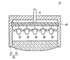
図1は、本発明の第1の実施形態に係る車両用灯具10の断面図の一例を示す。車両用灯具10は、例えば自動車等の車両の車体に設けられ、ストップランプ、テールランプ、ターンランプ等に用いられる。本例の車両用灯具10は、光源30の断線を示す情報をランプボディ20の外部に通知する。
【0016】
車両用灯具10は、ランプボディ20、回路基板40、複数の光源30、及び配線32を備える。ランプボディ20は、光源30が生成した光を透過する透過部24と、回路基板40及び複数の光源30を格納するためのホルダ22を有する。透過部24は、光源30が生成した光を拡散又は集光するレンズであってよい。また、ランプボディ20は、複数の光源30及び回路基板40を防水する機能を有する。つまり、ランプボディ20は、複数の光源30及び回路基板40を密閉する。また、ランプボディ20は開口部を有し、車両の車体に取り付けられることにより、当該開口部が遮蔽され、複数の光源30及び回路基板40を密閉及び防水してもよい。
【0017】
複数の光源30は、与えられた電力により発光する。本例において複数の光源30は、発光ダイオードである。回路基板40は、複数の光源30に供給する電力を制御する。回路基板40は、配線32を介して外部の電源から電力が供給され、供給された電力を調整し、光源30に供給する。ここで、外部の電源とは、例えば自動車等の車両のバッテリである。また、本例において、車両用灯具10は複数の光源30を備えていたが、他の例においては、車両用灯具10は、一の光源30を備える構成であってもよい。
【0018】
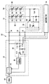
図2は、車両用灯具10と、車両用灯具10に電力を供給するフラッシャーリレーユニット26との回路構成の一例を示す。車両用灯具10とフラッシャーリレーユニット26とは、配線32を介して電気的に接続される。配線32は、フラッシャーリレーユニット26から光源30へ電力を伝送する2本の電力伝送線と、電力伝送線と電気的に独立な断線情報通知線とを有する。
【0019】
車両用灯具10は、一の電力伝送線と電気的に接続された端子34を介して、フラッシャーリレーユニット26から正電圧を受け取り、他の電力伝送線と電気的に接続された端子38を介して、フラッシャーリレーユニット26の接地電位と電気的に接続される。また、車両用灯具10は、光源30の断線を検出し、当該断線を示す情報を、断線情報通知線と電気的に接続された端子36を介して、ランプボディ20(図1参照)の外部に設けられたフラッシャーリレーユニット26に通知する。
【0020】
車両用灯具10は、光源ブロック58と、光源ブロック58に直列に接続された断線検出部28とを備える。光源ブロック58は、一端が端子34と電気的に接続されることにより並列に接続された、複数の光源ユニット60を有する。また、複数の光源ユニット60のそれぞれは、直列に接続された一個以上の光源30を含む。
【0021】
断線検出部28は、回路基板40(図1参照)上に設けられ、複数の光源ユニット60に対応して設けられた、複数の抵抗104及び複数のPNPトランジスタ102を有する。抵抗104は、対応する光源ユニット60に流れる電流に基づく電圧を、PNPトランジスタ102のベース端子に与える。
【0022】
ここで、いずれかの光源30が断線した場合、抵抗104には電流が流れないため、PNPトランジスタ102はオンになって、端子36から受け取るコレクタ電流を、接地電位にシンクする(Sink、吸い込ませる)。これにより、断線検出部28は、複数の光源30の少なくとも一つが断線した場合に、断線を検出し、断線の有無を示す断線情報を、端子36を介してフラッシャーリレーユニット26に通知する。
【0023】
一方、いずれの光源30も断線していない場合、光源ユニット60に流れる電流が抵抗104に流れるため、PNPトランジスタ102はオフになる。本例によれば、光源30の断線を適切に検出して、検出結果を適切にフラッシャーリレーユニット26に通知することができる。
【0024】
フラッシャーリレーユニット26は、予め定められた周期で断続する電力を車両用灯具10に供給することにより、複数の光源30を点滅させる。本例において、フラッシャーリレーユニット26は、例えば車両のバッテリである電源56から受け取る直流電力に基づく電力を、例えば車両の左右のターンランプである2個の車両用灯具10に供給する。尚、電源56は、例えば、車両のエンジンを制御する制御装置や、車両の室内に設置された室内灯等に、更に電力を供給する。
【0025】
フラッシャーリレーユニット26は、リレー42、リレー制御部44、及び断線情報受信部46を備える。リレー42は、電源56から受け取る直流電力を予め定められた周期で断続させて、断続する電力を、2本の電力伝送線を介して車両用灯具10に供給する。
【0026】
断線情報受信部46は、NPNトランジスタ110、抵抗112、抵抗114、及び抵抗116を有する。NPNトランジスタ110のベース端子は、抵抗114を介して断線検出部28と電気的に接続される。
【0027】
抵抗112は、断線情報受信部46の入力端に設けられたプルアップ抵抗である。断線検出部28が光源30の断線を検出しない場合(以下、断線非検出時という)、抵抗112、抵抗114、及び抵抗116は、フラッシャーリレーユニット26が出力する正電圧を、これらの抵抗比に応じて分割した電圧を、NPNトランジスタ110のベース端子に供給することにより、NPNトランジスタ110をオンに保つ。この場合、NPNトランジスタ110は、リレー制御部44から受け取るコレクタ電流を接地電位にシンクする。
【0028】
一方、断線検出部28が光源30の断線を検出した場合(以下、断線検出時という)、NPNトランジスタ110はオフになる。これにより、断線情報受信部46は、断線検出部28から受け取った断線情報をリレー制御部44に伝達する。尚、NPNトランジスタ110は、いずれかの車両用灯具10における断線検出部28が断線を検出した場合にオンになり、断線情報をリレー制御部44へ伝達する。本例によれば、フラッシャーリレーユニット26は、光源30の断線を精度よく検出することができる。
【0029】
リレー制御部44は、断線情報受信部46の出力に応じて、リレー42の断続する周期を変更する。本例において、リレー制御部44は、断線検出時に、リレー42の断続する周期を短くする。この場合、車両の運転者等は、光源30の点滅の周期を観察することにより、光源30の断線の有無を確認することができる。
【0030】
他の形態としては、車両の制御パネル上に、光源30の点滅状態を示すインジケータLED(発光ダイオード)を設け、フラッシャーリレーユニット26により、当該インジケータLEDを駆動してもよい。この場合、車両の運転者等は、更に容易に、光源30の断線の有無を確認することができる。
【0031】
ここで、フラッシャーリレーユニット26が、例えば、車両用灯具10の消費電力に基づいて光源30の断線を検出するとすれば、フラッシャーリレーユニット26に、当該消費電流を検出する電流検出器を設けなければならない。当該電流検出器は、例えば、車両用灯具10の消費電流を、予め定められた閾電流値と比較することにより、光源30の断線を検出する。
【0032】
しかし、発光ダイオードを備える車両用灯具10は、発光ダイオードの並列数及び/又は直列数に応じた電流を消費する。そのため、この場合、車両用灯具10の種類に応じてそれぞれ異なる閾電流値を有する電流検出器を用いる必要があり、フラッシャーリレーユニット26を標準化し難い。
【0033】
しかし、本例のフラッシャーリレーユニット26は、車両用灯具10の消費電力によらずに、光源30の断線を検出する。そのため、本例によれば、1種類のフラッシャーリレーユニット26に対応して、それぞれ消費電力が異なる複数種類の車両用灯具10を提供することができる。また、これにより、車両のターンランプを駆動するフラッシャーリレーを標準化することができる。
【0034】
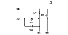
図3は、断線検出部28の回路構成の他の例を示す。本例において、断線検出部28は、複数のPNPトランジスタ102に代えて、複数のダイオード106を有する。本例において、いずれかの光源30が断線した場合、これに対応する抵抗104はダイオード106のカソードの電位を低下させる。これにより、ダイオード106は、順方向バイアスされ、端子36から受け取る電流を接地電位にシンクする。この場合も、光源30の断線を適切に検出して、検出結果を適切にフラッシャーリレーユニット26に通知することができる。
【0035】
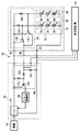
図4は、車両用灯具10及びフラッシャーリレーユニット26の回路構成の他の例を示す。図4において、図2と同じ符号を付した構成は、図2における構成と同一又は同様の機能を有するため説明を省略する。
【0036】
本例において、複数の光源ユニット60は、一端が端子38と電気的に接続されることにより、並列に接続される。また、断線検出部28は、複数のPNPトランジスタ102に代えて、複数のNPNトランジスタ118を有する。いずれかの光源30が断線した場合、これに対応するNPNトランジスタ118は、オンになり、端子36にコレクタ電流をソース(供給)する。そのため、本例においても、光源30の断線を適切に検出して、検出結果を適切にフラッシャーリレーユニット26に通知することができる。
【0037】
また、本例において、断線情報受信部46は、PNPトランジスタ120、抵抗122、抵抗124、及び抵抗126を有する。PNPトランジスタ120のベース端子は、抵抗124を介して断線検出部28と電気的に接続される。
【0038】
抵抗122は、断線情報受信部46の入力端に設けられたプルダウン抵抗である。断線非検出時において、抵抗126、抵抗124、及び抵抗122は、フラッシャーリレーユニット26が出力する正電圧を、これらの抵抗比に応じて分割した電圧を、PNPトランジスタ120のベース端子に供給することにより、PNPトランジスタ120をオンに保つ。また、NPNトランジスタ110は、断線検出時にオフになる。これにより、断線情報受信部46は、断線検出部28から受け取った断線情報をリレー制御部44に伝達する。本例によっても、フラッシャーリレーユニット26は、光源30の断線を精度よく検出することができる。
【0039】
図5は、図4に関連して説明した車両用灯具10における、断線検出部28の回路構成の他の例を示す。本例において、断線検出部28は、複数のNPNトランジスタ118に代えて、複数のダイオード106を有する。本例において、いずれかの光源30が断線した場合、これに対応する抵抗104は、ダイオード106のアノードの電位を上昇させる。これにより、ダイオード106は、順方向バイアスされ、端子34から受け取る電流を端子36にソースする。この場合も、光源30の断線を適切に検出して、検出結果を適切にフラッシャーリレーユニット26に通知することができる。
【0040】
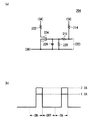
図6は、本発明の第2の実施形態に係る車両用灯具10の構成の一例を示す。図6(a)は、車両用灯具10の回路構成を示す。本例の車両用灯具10は、端子34及び端子36のそれぞれと電気的に接続された2本の電力伝送線の間のインピーダンスである伝送線間インピーダンスを変化させることにより、光源30の断線を示す情報をランプボディ20(図1参照)の外部に設けられたフラッシャーリレーユニット26に通知する。
【0041】
本例において、車両用灯具10は、光源ブロック58、断線検出部28、出力伝達部202、及びインピーダンス変更部204を有する。図6において、図2と同じ符号を付した構成は、図2における構成と同一又は同様の機能を有するため説明を省略する。
【0042】
尚、本例において、車両用灯具10は、図2に関連して説明したフラッシャーリレーユニット26に代えて、伝送線間インピーダンスを測定する機能を有するフラッシャーリレーユニット26から電力を受け取る。このような、インピーダンスを検出する回路は、多様な回路が知られているため説明を省略する。また、本例において、フラッシャーリレーユニット26は、伝送線間インピーダンスが予め定められた値より小さい場合に、光源30の断線を検出する。
【0043】
出力伝達部202は、NPNトランジスタ206、抵抗208、抵抗210、及び抵抗212を有する。NPNトランジスタ206、抵抗208、抵抗210、及び抵抗212のそれぞれは、断線情報受信部46(図2参照)における、NPNトランジスタ110、抵抗112、抵抗114、及び抵抗116のそれぞれと同一又は同様の機能を有する。これにより、出力伝達部202は、断線情報受信部46と同一又は同様の機能を有し、断線検出部28から受け取った断線情報を、次段のインピーダンス変更部204に伝達する。尚、NPNトランジスタ206は、断線非検出時にオンになることにより、コレクタ電流を接地電位にソースする。また、NPNトランジスタ206は、断線検出時にオフになる。
【0044】
インピーダンス変更部204は、NPNトランジスタ216、抵抗222、抵抗214、抵抗218、及び抵抗220を有する。NPNトランジスタ216は、光源30と並列に接続されたスイッチの一例である。NPNトランジスタ216のベース端子は、抵抗218を介して出力伝達部202の出力端であるNPNトランジスタ206のコレクタ端子と電気的に接続される。NPNトランジスタ216のコレクタ端子は、抵抗222を介して端子34と電気的に接続され、エミッタ端子は接地される。また、抵抗218のNPNトランジスタ216に近い一端は抵抗220を介して接地され、他端は抵抗214を介して端子34と電気的に接続される。
【0045】
抵抗222は、光源30と並列かつNPNトランジスタ216と直列に接続され、NPNトランジスタ216がオンになった場合に、一の電力伝送線から他の電力伝送線への伝送線間電流を流すことにより、NPNトランジスタ216にコレクタ電流を供給する。
【0046】
ここで、断線非検出時においては、NPNトランジスタ206がコレクタ電流をシンクするため、NPNトランジスタ216はオフになる。この場合、抵抗222は、伝送線間電流を流さないため、伝送線間インピーダンスは大きい。
【0047】
一方、断線検出時においては、NPNトランジスタ206がオフになるため、抵抗214、抵抗218、及び抵抗220は、フラッシャーリレーユニット26が出力する正電圧を、これらの抵抗比に応じて分割した電圧をNPNトランジスタ216のベース端子に供給する。そのため、NPNトランジスタ216は、オンになり、抵抗222から受け取るコレクタ電流を、接地電位にシンクすることにより、抵抗222に伝送線間電流を流す。
【0048】
これにより、断線検出時、インピーダンス変更部204は、伝送線間インピーダンスを小さな値に変更する。本例によれば、断線検出部28は、インピーダンス変更部204に伝送線間インピーダンスを変更させることにより、断線を示す情報をフラッシャーリレーユニット26に通知することができる。
【0049】
図6(b)は、断線検出時における、抵抗222の消費電流の一例を示す。本例において、光源30は、予め定められた周期で断続する電力を受け取って点滅する。そのため、抵抗222の消費電流は、光源30が点灯する期間(ON)に増大し、光源30が点灯しない期間(OFF)に略零となる。
【0050】
尚、本例において、断線検出部28は、光源30が電力を受け取る期間に断線を検出する。フラッシャーリレーユニット26は、当該期間に、車両用灯具10の消費電流を検知することにより、光源30の断線を検出することができる。
【0051】
また、本例において、断線検出時における車両用灯具10の消費電流は、断線非検出時における消費電流から大きく変化する。そのため、本例によれば、フラッシャーリレーユニット26は、光源30の消費電流によらず、高い精度で断線を検出することができる。そのため、本例によればフラッシャーリレーの標準化を行うことができる。
【0052】
断線が検出された場合、車両用灯具10は、例えば、正常時の略2倍の電流を消費する。この場合、フラッシャーリレーユニット26は、高い精度で光源30の断線を検出することができる。例えば、正常時における車両用灯具10が1.8Aの電流を消費するとすれば、断線が検出された場合における車両用灯具10は、3.6A程度の電流を消費する。この場合、一の光源30の断線により、抵抗222以外における車両用灯具10の消費電流が例えば1.4A程度に減少するとすれば、抵抗222は、断線検出時に、2.2A程度の電流を消費する。
【0053】
また、断線が検出された場合、車両用灯具10は、正常時の略1.5倍の電流を消費してもよい。この場合、断線が検出された場合の車両用灯具10の消費電流を低減することができる。また、この場合、抵抗222は、断線検出時に、1.3A程度の電流を消費してよい。
【0054】
図7(a)は、インピーダンス変更部204の回路構成を示す。図7(a)において、図6と同じ符号を付した構成は、図6における構成と同一又は同様の機能を有するため説明を省略する。
【0055】
本例において、インピーダンス変更部204は、NPNトランジスタ216のベース端子を接地するコンデンサ226を更に有する。コンデンサ226は、光源30が電力を受け取る期間(以下、供給オン期間という)において、断線検出時、NPNトランジスタ216のベース電圧を、漸増して変化させることにより、伝送線間電流を漸増させながら変化させる。
【0056】
これにより、コンデンサ226は、伝送線間電流が予め定められた基準電流値より大きくなる時間を制限する。すなわち。供給オン期間において、コンデンサ226は、伝送線間インピーダンスが予め定められた値より小さくなる時間を制限する。
【0057】
図7(b)は、断線検出時における抵抗222の消費電流の一例を示す。本例において、抵抗222は、供給オン期間において、漸増する伝送線間電流を消費する。すなわち、光源30が電力を受け取った直後において、抵抗222の消費電流は小さい。そのため、本例によれば、抵抗222の消費電力を低減することができる。また、この場合、抵抗222の発熱が低減されるため、車両用灯具10のサイズを小さくすることができる。
【0058】
尚、車両用灯具10に供給する電流が所定の上限値より大きくなった場合、フラッシャーリレーユニット26は、車両用灯具10への電力供給を停止して、光源30(図6参照)を消灯させるのが好ましい。また、断線検出時において、フラッシャーリレーユニット26は、当該上限値、及び伝送線間電流の増大する傾きに基づいて定められた短い周期で、車両用灯具10に供給する電力を断続させてよい。
【0059】
図8(a)は、インピーダンス変更部204の回路構成を示す。図8(a)において、図7(a)と同じ符号を付した構成は、図7における構成と同一又は同様の機能を有するため説明を省略する。
【0060】
本例において、インピーダンス変更部204は、NPNトランジスタ216に代えて、NMOSトランジスタ224を有する。この場合、コンデンサ226は、NMOSトランジスタ224のゲート電圧を、漸増して変化させる。NMOSトランジスタ224は、ゲート電圧が予め定められた閾値より大きくなった場合にオンになり、抵抗222に伝送線間電流を流し、これにより、2本の電力伝送線間のインピーダンスを、小さな値に変化させる。
【0061】
図8(b)は、断線検出時における抵抗222の消費電流の一例を示す。本例において、抵抗222は、NMOSトランジスタ224のゲート電圧が予め定められた閾値より大きくなった後に伝送線間電流を消費する。すなわち、光源30が電力を受け取った直後において、抵抗222の消費電流は略零である。そのため、本例によれば、抵抗222の消費電力を低減することができる。
【0062】
図9(a)は、インピーダンス変更部204の回路構成を示す。図9(a)において、図7(a)と同じ符号を付した構成は、図7における構成と同一又は同様の機能を有するため説明を省略する。
【0063】
本例において、インピーダンス変更部204は、アノードが接地され、カソードがNPNトランジスタ216のコレクタ端子と電気的に接続されたダイオード230を更に有する。また、抵抗222は、コンデンサ226を介して端子34と電気的に接続される。
【0064】
断線検出時、コンデンサ226は、抵抗222を流れる伝送線間電流に伴う電荷を蓄積することにより、伝送線間電流を漸減させながら変化させる。これにより、供給オン期間において、コンデンサ226は、伝送線間インピーダンスが予め定められた値より小さくなる時間を制限する。尚、ダイオード230は、光源30が電力を受け取らない期間(以下、供給オフ期間という)にコンデンサ226を放電する。
【0065】
図9(b)は、断線検出時の、本例における抵抗222の消費電流の一例を示す。供給オン期間において、コンデンサ226は、2本の電力伝送線間のインピーダンスを、当該期間の最初に、最も小さな値に変化させた後に、漸増して変化させる。そのため、抵抗222は、漸減する伝送線間電流を消費する。コンデンサ226は、フラッシャーリレーユニット26が伝送線間インピーダンスを測定する期間に伝送線間電流を流し、その後は、伝送線間電流を略零に低下させるのが好ましい。本例によれば、抵抗222の消費電力を低減することができる。
【0066】
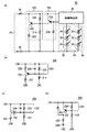
図10は、車両用灯具10構成の更なる他の例を示す。図10(a)は、車両用灯具10の回路構成を示す。本例において、車両用灯具10は、断線検出部28、光源ブロック58、出力伝達部202及びインピーダンス変更部204を備える。断線検出部28及び光源ブロック58は、図4に関連して説明した断線検出部28及び光源ブロック58と同一又は同様の機能を有するため説明を省略する。車両用灯具10は、図6に関連して説明した車両用灯具10へ電力を供給するフラッシャーリレーユニット26と同一又は同様の機能を有するフラッシャーリレーユニット26から電力を受け取る。
【0067】
出力伝達部202は、PNPトランジスタ236及び抵抗208を有する。PNPトランジスタ236及び抵抗208のそれぞれは、断線情報受信部46(図4参照)における、PNPトランジスタ120及び抵抗122のそれぞれと同一又は同様の機能を有する。これにより、出力伝達部202は、図4の断線情報受信部46と同一又は同様の機能を有し、断線検出部28から受け取った断線情報を、次段のインピーダンス変更部204に伝達する。尚、PNPトランジスタ236は、断線非検出時にオンとなり、断線検出時にオフとなる。
【0068】
インピーダンス変更部204は、PNPトランジスタ232、抵抗222、抵抗214、及び抵抗220を有する。PNPトランジスタ120のベース端子は、PNPトランジスタ236のコレクタ端子と、エミッタ端子は端子34と、それぞれ電気的に接続され、コレクタ端子は抵抗222を介して接地される。
【0069】
これにより、PNPトランジスタ232は、断線検出時にオンになり、抵抗222に伝送線間電流を流し、伝送線間インピーダンスを小さい値に変更する。本例によれば、断線検出部28は、インピーダンス変更部204に伝送線間インピーダンスを変更させることにより、断線を示す情報をフラッシャーリレーユニット26に通知することができる。
【0070】
図10(b)は、インピーダンス変更部204の回路構成の他の例を示す。本例において、インピーダンス変更部204は、コンデンサ226を更に有する。コンデンサ226は、図7(a)に関連して説明したコンデンサ226と同一又は同様の機能を有する。コンデンサ226は、PNPトランジスタ232のベース端子と端子34とを電気的に接続させ、断線検出時の供給オン期間に、NPNトランジスタ216のベース電圧を、漸減して変化させることにより、伝送線間電流を漸増させながら変化させる。本例によれば、抵抗222の消費電力を低減することができる。
【0071】
図10(c)は、インピーダンス変更部204の回路構成の更なる他の例を示す。本例において、インピーダンス変更部204は、PNPトランジスタ232に代えて、PMOSトランジスタ234を有する。また、コンデンサ226は、図8(a)に関連して説明したコンデンサ226と同一又は同様の機能を有する。PMOSトランジスタ234は、ゲート電圧が予め定められた閾値より小さい場合にオンする。コンデンサ226は、PMOSトランジスタ234のゲート電圧を、漸減して変化させる。本例によれば、抵抗222の消費電力を低減することができる。
【0072】
図10(d)は、インピーダンス変更部204の回路構成の更なる他の例を示す。本例において、インピーダンス変更部204は、カソードが端子34と電気的に接続され、アノードがPNPトランジスタ232のコレクタ端子と電気的に接続されたダイオード230を更に有する。また、抵抗222は、コンデンサ226を介して端子38と電気的に接続される。本例において、コンデンサ226及びダイオード230は、図9(a)におけるコンデンサ226及びダイオード230と同一又は同様の機能を有する。本例によれば、抵抗222の消費電力を低減することができる。尚、図10(b)〜(d)のそれぞれにおいて、図10(a)と同じ符号を付した構成は、図10(a)における構成と同一又は同様の機能を有してよい。
【0073】
図11は、車両用灯具10の回路構成の更なる他の例を示す。本例において、車両用灯具10は、図2に関連して説明したフラッシャーリレーユニット26に代えて、伝送線間インピーダンスを測定する機能を有するフラッシャーリレーユニット26から電力を受け取る。このような、インピーダンスを検出する回路は、多様な回路が知られているため説明を省略する。また、本例において、フラッシャーリレーユニット26は、伝送線間インピーダンスが予め定められた値より大きい場合に、光源30の断線を検出する。また、フラッシャーリレーユニット26は、供給オフ期間に、光源30の断線の有無を確認する。
【0074】
車両用灯具10は、光源ブロック58、断線検出部28、出力伝達部202、抵抗302、コンデンサ304、インピーダンス変更部204、及びダイオード314を備える。
【0075】
本例において、出力伝達部202は、供給オン期間に、断線検出部28から受け取る断線情報に基づく値を、抵抗302を介してコンデンサ304に供給する。その他の点において、光源ブロック58、断線検出部28、出力伝達部及び202のそれぞれは、図6における光源ブロック58、断線検出部28、及び出力伝達部202のそれぞれと同一又は同様の機能を有するため説明を省略する。
【0076】
コンデンサ304は、出力伝達部202の出力を受け取る一端に対する他端が接地されており、出力伝達部202から受け取った値を、供給オフ期間に保持する。供給オン期間において、コンデンサ304は、断線検出時には充電され、断線検出時には放電される。これにより、コンデンサ304は、断線検出部28が断線を検出したか否かを示す値を、供給オフ期間保持する。尚、コンデンサ304は、例えば、数10〜数100μF程度の容量を有する。この場合、コンデンサ304は、0.1〜1秒程度の期間、インピーダンス変更部204から受け取る信号の値を保持することができる。また、コンデンサ304は、供給オフ期間に、保持する当該値を、インピーダンス変更部204に与える。
【0077】
インピーダンス変更部204は、NPNトランジスタ216、抵抗222、抵抗214、抵抗218、抵抗220、NPNトランジスタ306、抵抗308、及びダイオード312を有する。NPNトランジスタ216、抵抗222、抵抗214、抵抗218、及び抵抗220のそれぞれは、図6におけるNPNトランジスタ216、抵抗214、抵抗218、及び抵抗220のそれぞれと同一又は同様の機能を有するため説明を省略する。また、本例において、抵抗308は、抵抗222より小さな抵抗値を有する。
【0078】
NPNトランジスタ306は、ベース端子がNPNトランジスタ206のコレクタ端子と、コレクタ端子が抵抗308を介して端子34と、それぞれ電気的に接続され、エミッタ端子が接地される。そのため、供給オフ期間において、NPNトランジスタ306は、断線検出時にオフになり、断線非検出時にオンになる。これにより、NPNトランジスタ306は、断線非検出時に、抵抗308に伝送線間電流を流す。
【0079】
そのため、インピーダンス変更部204は、供給オフ期間において、断線検出時に抵抗222に伝送線間電流を流し、断線非検出時に抵抗308に伝送線間電流を流す。これにより、インピーダンス変更部204は、断線検出時に、伝送線間インピーダンスを大きな値に変更する。すなわち、供給オフ期間において、断線検出時のインピーダンス変更部204は、コンデンサ304が保持する値に基づき、電力伝送線間インピーダンスを大きな値に変化させる。
【0080】
ここで、供給オン期間において、フラッシャーリレーユニット26は、光源ブロック58の両端に、複数の光源30のそれぞれにおける順方向バイアス電圧に基づく供給時電圧を印加する。一方、供給オフ期間において、フラッシャーリレーユニット26は、当該供給時電圧より小さな測定時電圧を端子34と端子38との間に印加して、車両用灯具10のインピーダンスを測定する。
【0081】
この場合、光源30は発光ダイオードであるため、供給オフ期間においては電流を流さない。そのため、フラッシャーリレーユニット26は、インピーダンス変更部204が変更した伝送線間インピーダンスの変化を、適切に検出することができる。本例によれば、断線検出部28は、インピーダンス変更部204に伝送線間インピーダンスを変更させることにより、断線を示す情報をフラッシャーリレーユニット26に通知することができる。
【0082】
また、本例において、インピーダンス変更部204は、電力伝送線間インピーダンスを、断線非検出時には低く保ち、断線検出時に、大きな値に変化させる。そのため、本例によれば、フラッシャーリレーユニット26として、例えば、フィラメントバルブ光源に対して電力を供給するリレーユニットと同一又は同様の機能を有するリレーユニットを用いることができる。この場合、普及している低いコストのリレーユニットにより、車両用灯具10を駆動することができる。
【0083】
尚、ダイオード312及びダイオード314は、車両用灯具10の逆接続保護用のダイオードである。車両用灯具10の入力が、フラッシャーリレーユニット26に対して逆接続された場合、ダイオード312は、端子38から受け取る電流を抵抗222を介して端子34へ供給する。また、ダイオード314は、光源30に流れる逆方向電流を遮断することにより、光源30を保護する。
【0084】
図12は、車両用灯具10の回路構成の更なる他の例を示す。図12において、図11と同じ符号を付した構成は、図11における構成と同一又は同様の機能を有するため説明を省略する。
【0085】
本例において、車両用灯具10は、図11に関連して説明したフラッシャーリレーユニット26に代えて、供給オフ期間に端子34の電位を測定する機能を有するフラッシャーリレーユニット26から電力を受け取る。このような、電位を測定する回路は、多様な回路が知られているため説明を省略する。また、本例において、フラッシャーリレーユニット26は、測定した端子34の電位が予め定められた値より小さい場合に、光源30の断線を検出する。これにより、フラッシャーリレーユニット26は、供給オフ期間に、光源30の断線の有無を確認する。
【0086】
本例において、車両用灯具10は、インピーダンス変更部204に代えて、保持値出力部316を有する。保持値出力部316は、抵抗342、抵抗320、及びダイオード318を有する。抵抗342は、一端がダイオード314のカソードと電気的に接続されたプルアップ抵抗であり、他端はダイオード318を介して端子34と電気的に接続される。また、抵抗320はダイオード318のカソードを接地する。ダイオード318は、アノードが抵抗302を介して出力伝達部202と接続され、カソードが端子34と電気的に接続される。
【0087】
ここで、供給オフ期間において、断線検出時には、コンデンサ304は充電されているため、コンデンサ304はダイオード318を順方向バイアスする。そのため、ダイオード318は、抵抗320に電流を流し、端子34の電位を上昇させる。また、これにより、保持値出力部316は、コンデンサ304が保持する値に対応する高い電位を端子34に出力する。
【0088】
一方、断線非検出時には、コンデンサ304は放電されているため、コンデンサ304はダイオード318を逆方向バイアスする。そのため、ダイオード318に流れる電流は略零であり端子34の電位は上昇しない。これにより、保持値出力部316は、コンデンサ304が保持する値に対応する低い電位を端子34に出力する。本例によれば、断線検出部28は、保持値出力部316にコンデンサ304が保持する値を出力させることにより、フラッシャーリレーユニット26に通知することができる。
【0089】
図13は、車両用灯具10の回路構成の更なる他の例を示す。図13において、図11と同じ符号を付した構成は、図11における構成と同一又は同様の機能を有するため説明を省略する。本例において、車両用灯具10は、図11に関連して説明したフラッシャーリレーユニット26と同一又は同様の機能を有するフラッシャーリレーユニット26から電力を受け取る。
【0090】
車両用灯具10はインピーダンス変更部204、抵抗302、及びコンデンサ304に代えて、抵抗340及び切り替え部322を有する。抵抗340は、光源ブロック58及び断線検出部28と並列に接続され、端子34と端子38とを電気的に接続する。
【0091】
切り替え部322は、コンデンサ346、抵抗330、抵抗344、抵抗332、PNPトランジスタ328、抵抗334、コンデンサ336、リレー用コイル326、リレー用スイッチ324、及びダイオード338を有する。
【0092】
リレー用コイル326及びリレー用スイッチ324は、リレーを構成する。リレー用コイル326は、PNPトランジスタ328と直列に接続されたコイルであり、リレー用スイッチ324を制御する。リレー用スイッチ324は、端子34とダイオード314との間に設けられたスイッチであり、リレー用コイル326に流れる電流に応じて、オン又はオフになる。本例において、リレー用スイッチ324は、リレー用コイル326に電流が流れる場合にオフになる。
【0093】
コンデンサ346は、供給オン期間において、断線非検出時には充電され、断線検出時には放電される。これにより、コンデンサ346は、断線検出部28が出力する値を記憶し、供給オフ期間に保持する。抵抗344、抵抗330、及び抵抗332は、断線非検出時に、フラッシャーリレーユニット26が出力する正電圧をこれらの抵抗比に応じて分割した電圧をコンデンサ346に供給する。
【0094】
コンデンサ336は、供給オン期間に端子34と電気的に接続され、フラッシャーリレーユニット26から端子34が受け取る電圧により充電される。そして、供給オフ期間に、コンデンサ336は、充電された電圧をリレー用コイル326に与える。
【0095】
PNPトランジスタ328は、ベース端子に、抵抗334を介してコンデンサ346が保持する値を受け取る。そのため、供給オフ期間において、PNPトランジスタ328は、断線検出時にオンになり、断線非検出時にオフになる。これにより、PNPトランジスタ328は、供給オフ期間において、断線検出時に、リレー用コイル326に、コンデンサ336からの電流を流す。この場合、リレー用スイッチ324はオフになり、端子34と端子38とは電気的に切断され、車両用灯具10のインピーダンスは大きくなる。尚、リレー用コイル326は、コンデンサ336に代えて、端子34から電流を受け取って流してもよい。
【0096】
一方、断線非検出時には、リレー用スイッチ324はオンになるため、車両用灯具10のインピーダンスは小さい。そのため、本例によれば、供給オフ期間に、端子34と端子38とのインピーダンスを測定することにより、光源30の断線の有無を確認することができる。本例によれば、断線検出部28は、切り替え部322を制御することにより、断線を示す情報をフラッシャーリレーユニット26に通知することができる。
【0097】
以上、本発明を実施の形態を用いて説明したが、本発明の技術的範囲は上記実施の形態に記載の範囲には限定されない。上記実施の形態に、多様な変更又は改良を加えることができる。その様な変更又は改良を加えた形態も本発明の技術的範囲に含まれ得ることが、特許請求の範囲の記載から明らかである。
【0098】
上記説明から明らかなように、本発明によれば車両用灯具が備える発光ダイオードの断線を適切に検出することができる。
【図面の簡単な説明】
【図1】本発明の実施形態に係る車両用灯具10の断面図の一例を示す。
【図2】車両用灯具10と、フラッシャーリレーユニット26との回路構成の一例を示す。
【図3】断線検出部28の回路構成の他の例を示す。
【図4】車両用灯具10及びフラッシャーリレーユニット26の回路構成の他の例を示す。
【図5】断線検出部28の回路構成の他の例を示す。
【図6】車両用灯具10の構成の一例を示す。
図6(a)は、車両用灯具10の回路構成を示す。
図6(b)は、抵抗222の消費電流の一例を示す。
【図7】インピーダンス変更部204の構成の他の例を示す。
図7(a)は、インピーダンス変更部204の回路構成を示す。
図7(b)は、抵抗222の消費電流の一例を示す。
【図8】インピーダンス変更部204の構成の更なる他の例を示す。
図8(a)は、インピーダンス変更部204の回路構成を示す。
図8(b)は、抵抗222の消費電流の一例を示す。
【図9】インピーダンス変更部204の構成の更なる他の例を示す。
図9(a)は、インピーダンス変更部204の回路構成を示す。
図9(b)は、抵抗222の消費電流の一例を示す。
【図10】車両用灯具10構成の更なる他の例を示す。
図10(a)は、車両用灯具10の回路構成を示す。
図10(b)は、インピーダンス変更部204の回路構成の他の例を示す。
図10(c)は、インピーダンス変更部204の回路構成の更なる他の例を示す。
図10(d)は、インピーダンス変更部204の回路構成の更なる他の例を示す。
【図11】車両用灯具10の回路構成の更なる他の例を示す。
【図12】車両用灯具10の回路構成の更なる他の例を示す。
【図13】車両用灯具10の回路構成の更なる他の例を示す。
【符号の説明】
10・・・車両用灯具、20・・・ランプボディ、22・・・ホルダ、24・・・透過部、26・・・フラッシャーリレーユニット、28・・・断線検出部、30・・・光源、32・・・配線、34・・・端子、36・・・端子、38・・・端子、40・・・回路基板、42・・・リレー、44・・・リレー制御部、46・・・断線情報受信部、56・・・電源、58・・・光源ブロック、60・・・光源ユニット、102・・・PNPトランジスタ、202・・・出力伝達部、204・・・インピーダンス変更部、206・・・NPNトランジスタ、316・・・保持値出力部、322・・・切り替え部、324・・・リレー用スイッチ、326・・・リレー用コイル、328・・・PNPトランジスタ[0001]
TECHNICAL FIELD OF THE INVENTION
The present invention relates to a vehicular lamp used for a vehicle.
[0002]
[Prior art]
Conventionally, a vehicular lamp using a filament bulb as a light source is known. In the lamp, for example, disconnection of the light source was detected by measuring the impedance of the lamp. Further, conventionally, there has been known an automotive lamp disconnection detecting device used for a multi-light type brake light or the like (for example, see Patent Document 1).
[0003]
[Patent Document 1]
JP-A-10-217851 (page 3-4, FIG. 1-3)
[0004]
[Problems to be solved by the invention]
However, when a light emitting diode is used as a light source, the light emitting diode emits light with a smaller current value than a filament bulb, and thus a lighting circuit having a large impedance may be used. In this case, the impedance of the lamp has a high value even when the light source is not disconnected. Therefore, conventionally, there has been a case where disconnection of the light source cannot be properly detected.
[0005]
Therefore, an object of the present invention is to provide a vehicular lamp capable of solving the above-mentioned problems. This object is achieved by a combination of features described in the independent claims. The dependent claims define further advantageous embodiments of the present invention.
[0006]
[Means for Solving the Problems]
That is, according to the first aspect of the present invention, a light source for a vehicle used in a vehicle, the light source having a light emitting diode that emits light based on electric power received from a power source provided outside the vehicle light, and a light source. The lamp body includes a lamp body that is housed and waterproofed, and a disconnection detection unit that detects disconnection of the light source and notifies the outside of the lamp body. In addition, a plurality of light sources connected in parallel may be provided, and the disconnection detection unit may detect the disconnection when at least one of the plurality of light sources is disconnected.
[0007]
In addition, the disconnection notification unit may notify the information indicating the disconnection to the outside of the lamp body via a disconnection information notification line that is electrically independent of a power transmission line that transmits power to the light source.
[0008]
Further, when the disconnection detecting unit detects the disconnection, the apparatus further includes an impedance changing unit that changes an impedance between the two power transmission lines that transmit power to the light source, and the disconnection detecting unit sets the impedance to the impedance changing unit. By changing the information, information indicating the disconnection may be notified to the outside of the lamp body. The impedance changing unit includes a switch connected in parallel with the light source, and a switch connected in parallel with the light source and in series with the switch, and when the switch is turned on, a transmission line from one power transmission line to another power transmission line. A disconnection detecting unit that, when detecting a disconnection, turns on a switch to cause a transmission line current to flow through the resistor, and causes the impedance changing unit to change the impedance to a small value. .
[0009]
Further, the light source receives power that is intermittent at a predetermined cycle, the disconnection detection unit detects disconnection during a period in which the light source receives power, and the impedance change unit detects when the disconnection detection unit detects a disconnection. The apparatus may further include a limiting capacitor that limits a time during which the impedance becomes smaller than a predetermined value by changing the transmission line current during the period.
[0010]
In addition, the light source receives power that is intermittent at a predetermined cycle, the disconnection detection unit detects disconnection during a period in which the light source receives power, and the vehicle lamp determines whether the disconnection detection unit has detected disconnection. Further comprising a holding capacitor that holds a value indicating the disconnection during a period in which the light source does not receive power. You may notify the outside of the body.
[0011]
Further, during a period in which the light source does not receive the power, the apparatus further includes an impedance changing unit that changes the impedance between the two power transmission lines that transmit the power to the light source based on the value held by the holding capacitor. Alternatively, the information indicating the disconnection may be notified to the outside of the lamp body by causing the impedance changing unit to change the impedance.
[0012]
Further, during a period in which the light source does not receive power, the apparatus further includes a holding value output unit that outputs a value held by the holding capacitor to the outside of the lamp body, and the disconnection detection unit outputs the value to the holding value output unit. Alternatively, information indicating the disconnection may be notified to the outside of the lamp body.
[0013]
Note that the above summary of the present invention does not list all of the necessary features of the present invention, and a sub-combination of these features may also be an invention.
[0014]
BEST MODE FOR CARRYING OUT THE INVENTION
Hereinafter, the present invention will be described through embodiments of the present invention. However, the following embodiments do not limit the invention according to the claims, and all of the combinations of the features described in the embodiments are not limited thereto. It is not always essential to the solution of the invention.
[0015]
FIG. 1 shows an example of a sectional view of a
[0016]
The
[0017]
The plurality of
[0018]
FIG. 2 shows an example of a circuit configuration of the
[0019]
The
[0020]
The
[0021]
The
[0022]
Here, if any of the
[0023]
On the other hand, if none of the
[0024]
The
[0025]
The
[0026]
The disconnection
[0027]
The
[0028]
On the other hand, when the
[0029]
The
[0030]
As another form, an indicator LED (light emitting diode) indicating the blinking state of the
[0031]
Here, assuming that the
[0032]
However, the
[0033]
However, the
[0034]
FIG. 3 shows another example of the circuit configuration of the
[0035]
FIG. 4 shows another example of the circuit configuration of the
[0036]
In this example, the plurality of
[0037]
In this example, the disconnection
[0038]
The
[0039]
FIG. 5 shows another example of the circuit configuration of the
[0040]
FIG. 6 shows an example of the configuration of the
[0041]
In this example, the
[0042]
In this example, the
[0043]
The
[0044]
The
[0045]
The
[0046]
Here, when no disconnection is detected, the
[0047]
On the other hand, at the time of disconnection detection, since the
[0048]
As a result, when disconnection is detected, the
[0049]
FIG. 6B shows an example of the current consumption of the
[0050]
In this example, the
[0051]
Further, in the present example, the current consumption of the
[0052]
When the disconnection is detected, the
[0053]
When a disconnection is detected, the
[0054]
FIG. 7A illustrates a circuit configuration of the
[0055]
In this example, the
[0056]
As a result, the
[0057]
FIG. 7B shows an example of the current consumption of the
[0058]
When the current supplied to the
[0059]
FIG. 8A shows a circuit configuration of the
[0060]
In this example, the
[0061]
FIG. 8B shows an example of the current consumption of the
[0062]
FIG. 9A shows a circuit configuration of the
[0063]
In this example, the
[0064]
At the time of disconnection detection, the
[0065]
FIG. 9B shows an example of the current consumption of the
[0066]
FIG. 10 shows still another example of the configuration of the
[0067]
The
[0068]
The
[0069]
As a result, the
[0070]
FIG. 10B shows another example of the circuit configuration of the
[0071]
FIG. 10C shows still another example of the circuit configuration of the
[0072]
FIG. 10D shows still another example of the circuit configuration of the
[0073]
FIG. 11 shows still another example of the circuit configuration of the
[0074]
The
[0075]
In this example, the
[0076]
The
[0077]
The
[0078]
The
[0079]
Therefore, during the supply OFF period, the
[0080]
Here, during the supply ON period, the
[0081]
In this case, since the
[0082]
Further, in this example, the
[0083]
Note that the
[0084]
FIG. 12 shows still another example of the circuit configuration of the
[0085]
In this example, the
[0086]
In this example, the
[0087]
Here, during the supply-off period, when disconnection is detected, the
[0088]
On the other hand, when disconnection is not detected, since the
[0089]
FIG. 13 shows still another example of the circuit configuration of the
[0090]
The
[0091]
The
[0092]
The
[0093]
The
[0094]
The
[0095]
The
[0096]
On the other hand, when disconnection is not detected, the
[0097]
As described above, the present invention has been described using the embodiments, but the technical scope of the present invention is not limited to the scope described in the above embodiments. Various changes or improvements can be added to the above embodiment. It is apparent from the description of the appended claims that embodiments with such changes or improvements can be included in the technical scope of the present invention.
[0098]
As is clear from the above description, according to the present invention, a disconnection of a light emitting diode included in a vehicle lamp can be appropriately detected.
[Brief description of the drawings]
FIG. 1 shows an example of a sectional view of a
FIG. 2 shows an example of a circuit configuration of the
FIG. 3 shows another example of the circuit configuration of the
4 shows another example of the circuit configuration of the
FIG. 5 shows another example of the circuit configuration of the
FIG. 6 shows an example of the configuration of the
FIG. 6A shows a circuit configuration of the
FIG. 6B shows an example of the current consumption of the
FIG. 7 shows another example of the configuration of the
FIG. 7A illustrates a circuit configuration of the
FIG. 7B shows an example of the current consumption of the
FIG. 8 shows still another example of the configuration of the
FIG. 8A shows a circuit configuration of the
FIG. 8B shows an example of the current consumption of the
9 shows still another example of the configuration of the
FIG. 9A shows a circuit configuration of the
FIG. 9B shows an example of the current consumption of the
FIG. 10 shows still another example of the configuration of the
FIG. 10A shows a circuit configuration of the
FIG. 10B shows another example of the circuit configuration of the
FIG. 10C shows still another example of the circuit configuration of the
FIG. 10D shows still another example of the circuit configuration of the
11 shows still another example of the circuit configuration of the
12 shows still another example of the circuit configuration of the
13 shows still another example of the circuit configuration of the
[Explanation of symbols]
DESCRIPTION OF
Claims (9)
前記車両用灯具の外部に設けられた電源から受け取る電力に基づいて発光する発光ダイオードを有する光源と、
前記光源を収容して防水するランプボディと、
前記光源の断線を検出して、前記ランプボディの外部に通知する断線検出部とを備えることを特徴とする車両用灯具。A vehicle lamp used for a vehicle,
A light source having a light-emitting diode that emits light based on electric power received from a power supply provided outside the vehicle lamp,
A lamp body for housing and waterproofing the light source;
And a disconnection detecting unit that detects disconnection of the light source and notifies the outside of the lamp body.
前記断線検出部は、前記複数の光源の少なくとも一つが断線した場合に、前記断線を検出することを特徴とする請求項1に記載の車両用灯具。Comprising a plurality of the light sources connected in parallel,
The vehicular lamp according to claim 1, wherein the disconnection detector detects the disconnection when at least one of the plurality of light sources is disconnected.
前記断線検出部は、前記インピーダンス変更部に前記インピーダンスを変更させることにより、前記断線を示す情報を前記ランプボディの外部に通知することを特徴とする請求項1に記載の車両用灯具。When the disconnection detecting unit detects the disconnection, further comprising an impedance changing unit that changes the impedance between two power transmission lines that transmit the power to the light source,
The vehicular lamp according to claim 1, wherein the disconnection detecting unit notifies the information indicating the disconnection to the outside of the lamp body by causing the impedance changing unit to change the impedance.
前記光源と並列に接続されたスイッチと、
前記光源と並列かつ前記スイッチと直列に接続され、前記スイッチがオンになった場合に、一の前記電力伝送線から他の前記電力伝送線への伝送線間電流を流す抵抗と
を有し、
前記断線検出部は、前記断線を検出した場合、前記スイッチをオンにして前記抵抗に前記伝送線間電流を流し、前記インピーダンス変更部に、前記インピーダンスを小さな値に変更させることを特徴とする請求項4に記載の車両用灯具。The impedance changing unit,
A switch connected in parallel with the light source,
A resistor connected in parallel with the light source and in series with the switch, and for flowing a current between transmission lines from one power transmission line to another power transmission line when the switch is turned on,
The disconnection detecting unit, when detecting the disconnection, turns on the switch, causes the current between the transmission lines to flow through the resistor, and causes the impedance changing unit to change the impedance to a small value. Item 5. The vehicle lamp according to item 4.
前記断線検出部は、前記光源が前記電力を受け取る期間に前記断線を検出し、
前記インピーダンス変更部は、前記断線検出部が前記断線を検出した場合に、前記期間において前記伝送線間電流を変化させることにより、前記インピーダンスが予め定められた値より小さくなる時間を制限する制限コンデンサを更に有することを特徴とする請求項5に記載の車両用灯具。The light source receives the power intermittently at a predetermined cycle,
The disconnection detection unit detects the disconnection during a period in which the light source receives the power,
The impedance changing unit, when the disconnection detecting unit detects the disconnection, by changing the current between the transmission lines in the period, a limiting capacitor that limits the time when the impedance becomes smaller than a predetermined value. The vehicular lamp according to claim 5, further comprising:
前記断線検出部は、前記光源が前記電力を受け取る期間に前記断線を検出し、
前記車両用灯具は、前記断線検出部が前記断線を検出したか否かを示す値を、前記光源が前記電力を受け取らない期間保持する保持コンデンサを更に備え、
前記断線検出部は、前記光源が前記電力を受け取らない期間に、前記保持コンデンサが保持する前記値に基づき、前記断線を示す情報を、前記ランプボディの外部に通知することを特徴とする請求項1に記載の車両用灯具。The light source receives the power intermittently at a predetermined cycle,
The disconnection detection unit detects the disconnection during a period in which the light source receives the power,
The vehicle lamp further includes a holding capacitor that holds a value indicating whether the disconnection detection unit has detected the disconnection, during a period in which the light source does not receive the power,
The said disconnection detection part notifies the information which shows the said disconnection to the exterior of the said lamp body based on the said value hold | maintained by the said holding capacitor during the period when the said light source does not receive the said electric power. 2. The vehicle lighting device according to 1.
前記断線検出部は、前記インピーダンス変更部に前記インピーダンスを変更させることにより、前記断線を示す情報を前記ランプボディの外部に通知することを特徴とする請求項7に記載の車両用灯具。During the period when the light source does not receive the power, based on the value held by the holding capacitor, further comprising an impedance changing unit that changes the impedance between two power transmission lines that transmit the power to the light source,
The vehicular lamp according to claim 7, wherein the disconnection detecting unit notifies the information indicating the disconnection to the outside of the lamp body by causing the impedance changing unit to change the impedance.
前記断線検出部は、前記保持値出力部に前記値を出力させることにより、前記断線を示す情報を前記ランプボディの外部に通知することを特徴とする請求項7に記載の車両用灯具。A period in which the light source does not receive the power, further includes a holding value output unit that outputs the value held by the holding capacitor to the outside of the lamp body,
The vehicular lamp according to claim 7, wherein the disconnection detection unit notifies the information indicating the disconnection to the outside of the lamp body by causing the held value output unit to output the value.
Priority Applications (4)
| Application Number | Priority Date | Filing Date | Title |
|---|---|---|---|
| JP2002289288A JP2004122913A (en) | 2002-10-01 | 2002-10-01 | Vehicle lighting fixture |
| US10/671,159 US6917166B2 (en) | 2002-10-01 | 2003-09-25 | Vehicular lamp |
| DE10345422A DE10345422B4 (en) | 2002-10-01 | 2003-09-30 | vehicle light |
| FR0311494A FR2845050B1 (en) | 2002-10-01 | 2003-10-01 | VEHICLE LAMP WITH PHOTODEGISSIVE DIODE FAILURE DETECTION CIRCUIT |
Applications Claiming Priority (1)
| Application Number | Priority Date | Filing Date | Title |
|---|---|---|---|
| JP2002289288A JP2004122913A (en) | 2002-10-01 | 2002-10-01 | Vehicle lighting fixture |
Publications (1)
| Publication Number | Publication Date |
|---|---|
| JP2004122913A true JP2004122913A (en) | 2004-04-22 |
Family
ID=31987156
Family Applications (1)
| Application Number | Title | Priority Date | Filing Date |
|---|---|---|---|
| JP2002289288A Pending JP2004122913A (en) | 2002-10-01 | 2002-10-01 | Vehicle lighting fixture |
Country Status (4)
| Country | Link |
|---|---|
| US (1) | US6917166B2 (en) |
| JP (1) | JP2004122913A (en) |
| DE (1) | DE10345422B4 (en) |
| FR (1) | FR2845050B1 (en) |
Cited By (9)
| Publication number | Priority date | Publication date | Assignee | Title |
|---|---|---|---|---|
| JP2007258033A (en) * | 2006-03-24 | 2007-10-04 | Toshiba Lighting & Technology Corp | Display device |
| US7329994B2 (en) | 2005-02-14 | 2008-02-12 | Koito Manufacturing Co., Ltd. | Lighting system for vehicle |
| JP2009006981A (en) * | 2007-05-30 | 2009-01-15 | Stanley Electric Co Ltd | Vehicular lighting fixture |
| JP2009255679A (en) * | 2008-04-15 | 2009-11-05 | Koito Mfg Co Ltd | Lighting control device |
| JP2010111356A (en) * | 2008-11-10 | 2010-05-20 | Koito Mfg Co Ltd | Light emitting device for vehicular lamp fitting |
| JP2014072172A (en) * | 2012-10-02 | 2014-04-21 | Ichikoh Ind Ltd | Energization control circuit of turn lamp unit for vehicle and energization control method of turn lamp unit for vehicle |
| KR20180135431A (en) * | 2018-12-04 | 2018-12-20 | 매그나칩 반도체 유한회사 | Detecting ciurcuit for open of led array and led driver apparatus having the same in |
| JP2021526104A (en) * | 2018-06-05 | 2021-09-30 | インディアン・モーターサイクル・インターナショナル・エルエルシー | Adaptive lighting system |
| US11465705B2 (en) | 2018-06-05 | 2022-10-11 | Indian Motorcycle International, LLC | Adaptive lighting system |
Families Citing this family (18)
| Publication number | Priority date | Publication date | Assignee | Title |
|---|---|---|---|---|
| JP4087211B2 (en) * | 2002-10-08 | 2008-05-21 | 株式会社小糸製作所 | Vehicle lighting |
| JP2004330819A (en) * | 2003-05-01 | 2004-11-25 | Koito Mfg Co Ltd | Lighting fixture for vehicle |
| FR2900534B1 (en) * | 2006-04-28 | 2011-01-14 | Peugeot Citroen Automobiles Sa | SYSTEM AND METHOD FOR DETECTING FAILURE OF LIGHT SOURCE, LIGHT SOURCE FOR THIS SYSTEM |
| US7649327B2 (en) * | 2006-05-22 | 2010-01-19 | Permlight Products, Inc. | System and method for selectively dimming an LED |
| EP1965609A3 (en) * | 2007-02-27 | 2011-06-15 | Lumination, LLC | LED chain failure detection |
| DE102008048701B4 (en) * | 2008-09-24 | 2020-06-04 | HELLA GmbH & Co. KGaA | Method for operating a series connection of at least two LEDs |
| US20100226139A1 (en) * | 2008-12-05 | 2010-09-09 | Permlight Products, Inc. | Led-based light engine |
| DE102009008465A1 (en) * | 2009-02-10 | 2010-08-19 | Siemens Aktiengesellschaft | Method for monitoring operability of circuit-breaker, involves determining variable depending on potential at contact point between coil and resistance element, and evaluating determined variable |
| DE102010049716A1 (en) | 2010-10-26 | 2012-04-26 | Automotive Lighting Reutlingen Gmbh | Composite of an on-board control unit and at least one light control device of a motor vehicle |
| DE102010064149A1 (en) * | 2010-12-24 | 2012-06-28 | Johann & Konen Gmbh & Co. Kg | Method for ensuring the correct evaluation of LED lights in combination with vehicle on-board computers |
| KR20120083005A (en) * | 2011-01-17 | 2012-07-25 | 삼성전자주식회사 | Apparatus and method for sensing fail |
| DE102011113080A1 (en) * | 2011-02-18 | 2012-08-23 | Volkswagen Aktiengesellschaft | Method for diagnosing e.g. tail light unit, of e.g. passenger car, involves detecting voltage potential at diagnostic port terminal of evaluation device, and generating diagnosis information based on detected potential |
| KR20130063863A (en) * | 2011-12-07 | 2013-06-17 | 매그나칩 반도체 유한회사 | Detecting ciurcuit for open of led array and led driver apparatus having the same in |
| SE539826C2 (en) | 2014-10-29 | 2017-12-12 | Scania Cv Ab | Compensation unit configured to be connected between a control unit and at least one LED lamp |
| DE102016121930A1 (en) | 2016-11-15 | 2018-05-17 | Ledvance Gmbh | lighting system |
| CN117087530A (en) * | 2018-04-25 | 2023-11-21 | 株式会社小糸制作所 | Tail steering lamp |
| US11027790B2 (en) * | 2018-06-05 | 2021-06-08 | Indian Motorcycle International, LLC | Adaptive lighting system |
| CN113597056A (en) * | 2020-04-30 | 2021-11-02 | 常州星宇车灯股份有限公司 | Circuit and control method for enabling bulb and LED to work simultaneously and achieving N-1 function |
Family Cites Families (8)
| Publication number | Priority date | Publication date | Assignee | Title |
|---|---|---|---|---|
| US4195281A (en) * | 1977-03-21 | 1980-03-25 | Essex Group, Inc. | Lamp outage indicator circuit |
| DE29515223U1 (en) * | 1995-09-26 | 1995-11-23 | Siemens Ag | Circuit board |
| DE19618010C1 (en) * | 1996-05-04 | 1997-07-03 | Hella Kg Hueck & Co | Flashing light indicator system with light-emitting diodes for motor vehicle |
| JP3250144B2 (en) | 1997-02-07 | 2002-01-28 | 株式会社マツショウ | Automotive lamp disconnection detector |
| DE19852351A1 (en) * | 1998-11-13 | 2000-05-18 | Hella Kg Hueck & Co | Diagnostic system for an LED light in a motor vehicle |
| EP1006506A1 (en) * | 1998-12-03 | 2000-06-07 | Hewlett-Packard Company | Optical vehicle display |
| US6362578B1 (en) * | 1999-12-23 | 2002-03-26 | Stmicroelectronics, Inc. | LED driver circuit and method |
| DE10107578A1 (en) * | 2001-02-17 | 2002-08-29 | Hella Kg Hueck & Co | Lighting system for motor vehicles |
-
2002
- 2002-10-01 JP JP2002289288A patent/JP2004122913A/en active Pending
-
2003
- 2003-09-25 US US10/671,159 patent/US6917166B2/en not_active Expired - Fee Related
- 2003-09-30 DE DE10345422A patent/DE10345422B4/en not_active Expired - Fee Related
- 2003-10-01 FR FR0311494A patent/FR2845050B1/en not_active Expired - Fee Related
Cited By (12)
| Publication number | Priority date | Publication date | Assignee | Title |
|---|---|---|---|---|
| US7329994B2 (en) | 2005-02-14 | 2008-02-12 | Koito Manufacturing Co., Ltd. | Lighting system for vehicle |
| JP2007258033A (en) * | 2006-03-24 | 2007-10-04 | Toshiba Lighting & Technology Corp | Display device |
| JP2009006981A (en) * | 2007-05-30 | 2009-01-15 | Stanley Electric Co Ltd | Vehicular lighting fixture |
| JP2009255679A (en) * | 2008-04-15 | 2009-11-05 | Koito Mfg Co Ltd | Lighting control device |
| JP2010111356A (en) * | 2008-11-10 | 2010-05-20 | Koito Mfg Co Ltd | Light emitting device for vehicular lamp fitting |
| JP2014072172A (en) * | 2012-10-02 | 2014-04-21 | Ichikoh Ind Ltd | Energization control circuit of turn lamp unit for vehicle and energization control method of turn lamp unit for vehicle |
| JP2021526104A (en) * | 2018-06-05 | 2021-09-30 | インディアン・モーターサイクル・インターナショナル・エルエルシー | Adaptive lighting system |
| JP7106683B2 (en) | 2018-06-05 | 2022-07-26 | インディアン・モーターサイクル・インターナショナル・エルエルシー | adaptive lighting system |
| US11465705B2 (en) | 2018-06-05 | 2022-10-11 | Indian Motorcycle International, LLC | Adaptive lighting system |
| US11878757B2 (en) | 2018-06-05 | 2024-01-23 | Indian Motorcycle International, LLC | Adaptive lighting system |
| KR20180135431A (en) * | 2018-12-04 | 2018-12-20 | 매그나칩 반도체 유한회사 | Detecting ciurcuit for open of led array and led driver apparatus having the same in |
| KR102034966B1 (en) | 2018-12-04 | 2019-10-22 | 매그나칩 반도체 유한회사 | Detecting ciurcuit for open of led array and led driver apparatus having the same in |
Also Published As
| Publication number | Publication date |
|---|---|
| US20040061450A1 (en) | 2004-04-01 |
| US6917166B2 (en) | 2005-07-12 |
| FR2845050A1 (en) | 2004-04-02 |
| DE10345422A1 (en) | 2004-04-22 |
| FR2845050B1 (en) | 2011-04-29 |
| DE10345422B4 (en) | 2009-06-04 |
Similar Documents
| Publication | Publication Date | Title |
|---|---|---|
| JP2004122913A (en) | Vehicle lighting fixture | |
| TWI455651B (en) | Led outage detection circuit | |
| US6927683B2 (en) | Vehicular turn signal indicator system and flasher circuit for the same | |
| JP5576892B2 (en) | LED lighting and disconnection detection control device | |
| US6963177B2 (en) | Open circuit detection for vehicular lamp | |
| JP2004009826A (en) | Lighting fixture apparatus for vehicle | |
| US7123136B2 (en) | Indicator system having multiple LEDs | |
| KR20110005878A (en) | Low loss input channel detection device for a direct current powered lighting system | |
| US20140232285A1 (en) | Direction indicating apparatus | |
| US7482763B2 (en) | Non-PWM vehicle lamp dimming arrangement | |
| WO2019208545A1 (en) | Rear turn lamp | |
| CN108235506B (en) | Constant current power driver circuit for vehicle lamp assembly | |
| JP6173874B2 (en) | Vehicle lighting | |
| US10368405B2 (en) | Two stage indicator dimming circuit controlled by PWM backlighting back feed and backlight control | |
| US11091088B2 (en) | Failure detection circuit for hybrid turn signal lamps | |
| US20070057676A1 (en) | Pulse shunt that allows for the use of light emitting diodes in vehicles that have a pulsed lamp check function in their external lighting system and/or trailers connected thereto | |
| US20200086781A1 (en) | Electrical circuit for accessory | |
| JP2008098495A (en) | Led fault detection apparatus | |
| JP2004039291A (en) | Lighting device | |
| EP2775801A1 (en) | Control device for turn indicator lamps, turn indicator device, and method for detecting wire breakages in turn indicator device | |
| JP6249555B2 (en) | Vehicle lighting | |
| CN214845699U (en) | Short circuit detection reminding circuit | |
| JP4259259B2 (en) | Indicator light device with multiple LEDs | |
| CN209930548U (en) | Car light auto-change over device and vehicle that has it | |
| KR950007556B1 (en) | Monitoring device for lamp |
Legal Events
| Date | Code | Title | Description |
|---|---|---|---|
| A621 | Written request for application examination |
Free format text: JAPANESE INTERMEDIATE CODE: A621 Effective date: 20050330 |
|
| A977 | Report on retrieval |
Free format text: JAPANESE INTERMEDIATE CODE: A971007 Effective date: 20070815 |
|
| A131 | Notification of reasons for refusal |
Free format text: JAPANESE INTERMEDIATE CODE: A131 Effective date: 20070821 |
|
| A521 | Written amendment |
Free format text: JAPANESE INTERMEDIATE CODE: A523 Effective date: 20071018 |
|
| A131 | Notification of reasons for refusal |
Free format text: JAPANESE INTERMEDIATE CODE: A131 Effective date: 20071225 |
|
| A02 | Decision of refusal |
Free format text: JAPANESE INTERMEDIATE CODE: A02 Effective date: 20080422 |