JP2004121771A - Stick with two-strut type stool - Google Patents
Stick with two-strut type stool Download PDFInfo
- Publication number
- JP2004121771A JP2004121771A JP2002321827A JP2002321827A JP2004121771A JP 2004121771 A JP2004121771 A JP 2004121771A JP 2002321827 A JP2002321827 A JP 2002321827A JP 2002321827 A JP2002321827 A JP 2002321827A JP 2004121771 A JP2004121771 A JP 2004121771A
- Authority
- JP
- Japan
- Prior art keywords
- stool
- support
- stick
- walking stick
- legged
- Prior art date
- Legal status (The legal status is an assumption and is not a legal conclusion. Google has not performed a legal analysis and makes no representation as to the accuracy of the status listed.)
- Pending
Links
Images


Abstract
Description
【0001】
【発明の属する技術分野】
この発明は、折りたたみ式腰掛けを組み込んだ歩行補助用ステッキに関する。
【0002】
【従来の技術】
折りたたみ腰掛け付きステッキのアイデアは多数あり、またいくつかの製品が国内外で市販されているが、休息用椅子としての機能を重視したものはステッキとしての機能、すなわち軽量歩行補助具としての簡便な携帯性がほとんど無く、ステッキ操作の携帯性を考慮したものは腰掛けとして使用した場合の安定性、快適性が欠ける。折りたたみ椅子としてはパイプ組み立ての4脚式が普及しているが、バッグあるいは車のトランクに収めて運ぶようにできており、ステッキとしての機能は全くない。3脚式は椅子機能を優先しており、携帯性をある程度考慮したステッキ付きのものが海外で開発生産され、国内にも輸入されている。しかし嵩張ること、比較的に重いこと、ステッキとしての操作時にステッキ以外の2本の脚部分が携帯者の脚や路面にしばしば当たるなど不快であり、歩行補助ステッキとしての使用はほとんど考慮されておらず、単に持ち運びの便利性のためにステッキ形に仕立てられている。実用化されている3脚式の使用目的は、車で目的地に乗り付けた後、それほど遠くない地点まで持ち運んで、ゴルフ、競馬その他のスポーツ観戦用の臨時椅子、キャンプ場での簡易椅子として利用するのが主体で、健常者のアウトドアライフ向きである。3脚式の国内のアイデアとして、下部がカメラ用3脚式に開く(特開平9−201215、特開平11−309007)ものや同格の3脚を中央で束ねる(実開平6−66338)もの、 登録実用新案(3065937号)があるが、いずれも3脚式のために嵩張り、かつ部品点数が多く重量が不利である。ステッキ機能を重視したものは、軽量性とステッキ操作性から1本脚式のものがいくつか発表されている。海外では取っ手部分を左右二つ割に展開して革張りあるいはキャンバス張りの座面でつなぎ、腰掛けるものが市販されている。しかしこれらはいずれも腰掛け時に、前後左右の揺れを支えるものが無く、不安定な座り方となり、ステッキ先端を地面に差し込める競馬場あるいはスポーツグラウンドでの観戦など健常者のアウトドア使用向きで、高齢者、足弱者の使用には危険が多い。国内でもステッキ棒にヒンジで腰掛けの一端を折りたたみ式に係合したアイデア(特開2001−299421、実開平5−82312)、取っ手を腰掛けにしたアイデア(特開平10−117821)が公開されているが、接地部が1本脚構造のために体重を預けるには安定性が欠ける。また構成部品が多く、腰掛けとして展開する、あるいはステッキに折りたたむ操作が煩雑であるため、足弱者あるいは高齢者の日常的な使用には適さない。1本脚に補助足を付けたアイデア(特開平8−332107)も公開されているが、基本は1本脚構造で荷重を受けるようになっており、補助足のある方向には良いがそれ以外の方向には不安定さがある。
【0003】
【発明が解決しようとする課題】
課題は二つあり、一つは足弱者や高齢者など本来、ステッキを必要とする人々が日常使用に不便のない程度に軽量化し、歩行時には構成部材折りたたみ部分の出っ張りを減らし、良好なステッキ携帯性を提供することである。他の一つは、安定性の良い堅牢な腰掛け構造により安心して休息できるようにすることである。本発明は、この相反する課題の解決を図るものである。
【0004】
【課題を解決するための手段】
上記課題解決のために講じた手段は、1本脚ステッキの軽量性と操作性を極力、形状面で活かしながら、腰掛けとしての安定性向上のために必要最小限の機構を加えたことである。これは自転車の力学を参考にして、試作と実験を繰り返した結果、一本脚と3脚式の中間である前後2脚式の構造を開発し、歩行時は部材を折りたたんでステッキに密着させた1本脚ステッキとして構成し、休息時は開いた前後2脚の接地に、左右両足を加えた4点支持にすることによって安定した着座が得られ、前記二つの課題を解決することができた。
【0005】
【作 用】
本発明の2脚式腰掛け付きステッキは、3脚式に比べて軽量で、脚の出っ張りが大幅に少ない。腰掛けを折りたたんで携行するときは、2脚が密着して1本脚の形状になる。また、休息時に腰掛けを展開したときは、腰掛けを地面と結ぶ2脚が前後方向に開いた三角形を上下に構成し、地面に対する位置関係が固定するので前後方向の揺れがない。また腰掛けた着座者の両足が左右に開いて地面を踏んでいるので、左右方向の揺れが両足で抑えられ、4点支持の安定した座姿勢が得られる。また三角形を構成するステッキ棒自体が地面に対して一定の角度で安定しているので、ステッキ棒の頭部取っ手を着座者が手で保持することによって、着座者の上体姿勢を安定させることができる。
【0006】
【実施例】
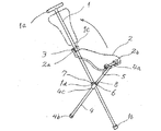
本発明の実施例1について図1の斜視図により説明する。構造を見やすくするため、腰掛け本体の形状を鎖線で示している。第一支柱(以下、ステッキ棒と称する)1は上端に取っ手1a、下端にゴム足1bを有し、中間やや上方の孔1cに折りたたみ式の腰掛け2のヒンジ2aをピン3で係合している。腰掛け2の下面に、左右に分かれた2個のヒンジ2bがあり、これに第二支柱(以下、支持棒と称する)4のT字状上端部4aがピン5を介して係合し、支持棒4は腰掛け荷重を支えるために地面にまで伸びて下端のゴム足4bで地面に接するが、中間の4cにおいてステッキ棒1とX字状に交叉し、支持棒4に嵌挿したヒンジ付き摺動部材6を配置し、ヒンジ付き摺動部材6はステッキ棒1に設けた孔1dに挿入したピン7によりステッキ棒1と係合している。腰掛け2の水平姿勢を保つために、支持棒4の摺動を一定ストロークに規定するストッパー8が支持神4に取り付けられている。ステッキとして使用するときは、腰掛け2を持ち上げてピン3回りに折りたたんでステッキ棒1に密着させ、支持棒4はヒンジ付き摺動部材6から上方へずり上がって、ピン7回りに回転しステッキ棒1に密着する。休息用腰掛けとして展開するときは、腰掛け2をステッキ棒1から開いてストッパー8がヒンジ付き摺動部材6に当たるまで押し下げる。ステッキ棒1と支持棒4がX字状に交叉し、ヒンジ係合で位置関係が固定するので、自転車に乗るように腰掛け2に座ることができる。全体を折りたたんだ状態の正面図を図10に示す。
【0007】
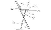
支持棒を摺動伸縮可能な二重筒とした実施例2の側面図を図2に示す。ヒンジ付き摺動部材6の機能と支持棒4の機能を一体化したヒンジ付き支持筒4xは中間部をピン7でステッキ棒1に係合しており、腰掛け2のヒンジ2bにT字状の上端4aをピン5で係合した支持棒心材4yがヒンジ付き支持筒4xの内部に挿入され、4xおよび4yからなる支持棒全体を伸縮可能にしている。腰掛け時の荷重は支持棒心材4yのT字状上端4aからヒンジ付き支持筒4xの上端に伝えられる。支持棒心材4yのT字状上端部4aと腰掛け2の係合関係は実施例1と同様で、この部分の正面形状は図10に示す通りである。腰掛け2を持ち上げるとステッキ棒1のヒンジ1eを中心にして回転し、支持棒心材4yが支持筒4xから引き出されて支持棒全体の長さが伸びて、腰掛け付きステッキ全体を折りたたむことができる。
【0008】
ステッキ棒1に摺動部材を嵌挿した実施例3の側面図を図3に示す。実線は腰掛け展開状態、2点鎖線は折りたたみ状態の摺動部材位置および展開した腰掛けに着座した人の姿勢を示す。全体構成は実施例1とほぼ同様であるが、以下が実施例1と異なる。摺動部材6をステッキ棒1に嵌挿し、腰掛け2の一端とヒンジ係合したことが実施例1と異なり、摺動部材6はステッキ棒の軸上で摺動する。この摺動により全体が折りたたみできるので、ステッキ棒1および支持棒4のX字状交叉点は摺動の必要が無くなり、位置固定式のヒンジ構造である。ステッキとしての使用時は、摺動部材6を支持棒4の上方へ摺動させて、腰掛け2をステッキ棒1に密着させて折りたたむ。腰掛けとして使用する時は、摺動部材6を下方に押し下げて腰掛け2を水平に展開する。摺動部材6が過剰に下がらないように、ステッキ棒1にストッパー8が留められている。以上のごとく実施例3は、実施例1に対して摺動部材6の配置軸を変更した2脚式腰掛け付きステッキである。X字状構成のステッキ棒あるいは支持棒の軸上でヒンジを摺動可能にした折りたたみ方式を説明したが、三角形を構成するいずれかの辺を伸縮可能にすれば、折りたたみが可能である。
【0009】
図4は腰掛け2の下面側に摺動レール2cを取り付けた実施例4の側面図である。実線は腰掛け展開状態、2点鎖線は折りたたみ状態を示す。腰掛け2はヒンジ1eを中心にして下方へ折りたたまれる。支持棒Aの上端にあるスライドピン4dは摺動レール2cの溝内で動き、腰掛け展開状態ではその位置が安定するように溝が上方に若干、深められている。
【0010】
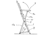
折りたたみをよりコンパクトに行うために支持棒4を上下に2分割した実施例5の側面図を図5に示す。実線の形は腰掛け展開状態を示し、2点鎖線は折りたたんだ状態を示している。折りたたんだ状態の腰掛け部分すなわち取っ手となる部分の正面図を図11に示す。この実施例は同一面内で折りたたむことができるので横方向張り出し量が少なく、便利な携帯性を目的にしている。腰掛け9の一端は、ステッキ棒1にヒンジ係合し、腰掛け9下面のヒンジ部9aに2分割した支持棒の上半部10aの上端がヒンジ係合している。折りたたみ状態では腰掛け9の上辺をステッキ棒の取っ手として使用するため、ステッキ棒1の上端と契合させている。契合の手段は多様であるが、腰掛け9の上辺下面中央に窪み9bを設け、ステッキ棒1の上部先端にばね作用で伸びる突起あるいはスライド式外筒を組み込んで、これの先端が前記の腰掛けの窪み9bに嵌るようにしてもよい。ステッキ棒1の中間部にチューブ状の摺動部材11が嵌挿されており、その上端に前記の上部支持棒10aの下端がヒンジ係合している。摺動部材11の下端に、下部支持棒10bの上端がヒンジ係合し、下部支持棒10bの下端は接地して腰掛けの荷重の一部を支える。この下部支持棒10bが所定の角度に開くように、ステッキ棒1のヒンジ1fおよび下部支持棒10bの下端ヒンジが拘束メンバー12により連結されている。この拘束メンバー12は下部支持棒10bの開き角度を展開時に所定値に維持できるものであれば、例えばストッパーとばね、ストラップなどの組み合わせでも良い。腰掛け9を水平に保持するため、摺動部材11が下がり過ぎないようにステッキ桐にストッパー8を設けている。上部支持棒10aと下部支持棒10bは摺動部材11を通じて連動する。今、腰掛けを折りたたむために引き起こすと、上部支持棒10aが摺動部材11を引っ張り上げ、つれて下部支持棒10bおよび拘束メンバー12が引き上げられて、それぞれがステッキ棒1に密着する。実施例1および2では支持棒がステッキ棒と干渉しないように側方に並列配置する必要があり、その分が横に張り出していたが、本実施例では支持棒を上下に分割し、中継の役割を持つ摺動部材11の背側と腹側に設けたヒンジにそれぞれ接続するので、同一平面内となり、側方交叉の必要が無く、コンパクトに折りたたむことができて携帯に便利である。
【0011】
実施例6の側面図を図6に示す。実施例5における2分割した支持棒の上側と下側の連動性を省き、折りたたみ/展開を上下で独立操作にしたものである。上部支持棒10aの機能と摺動部材13との連繋は実施例5と同じであるが、下部支持棒10cは摺動部材13の動きとは関係なく、ステッキ棒1に設けた固定のヒンジピン1gに係合し、手動で折りたたみ状態あるいは所定角度への展開を可能にしているが、下部支持棒10cがふらふらしないようにヒンジ部に摩擦材などを組み込んでいる。下部支持棒10cはまた、開脚角度を所定値に抑制するストッパーを有している。下部支持棒10cはコ字形断面のチャネル材を使用して支持棒1を囲むように密着でき、密着を保持するクリックストップを先端に有している。この構造は折りたたみ時の部材出っ張りがもっとも少ない。実施例5のワンアクションによる折りたたみ/展開に対して、2アクションにはなるが2脚式腰掛けとして同等の効果を有する。折りたたんだ状態の腰掛け部分の形状は、実施例5と同様に図11に示される。
【0012】
実施例6の腰掛けを取り外し式にして、ステッキとしての軽快性を高めた実施例7を図7に示す。摺動部材は不要となり、腰掛け使用時はステッキ棒1に固定したピン3に腰掛け14の前端、ピン5に支持棒10xの下端を嵌挿して腰掛けを固定できる。腰掛け14に支持棒10xがピン5で係合されている。ステッキとして使用するときは、腰掛け14および支持棒10xを上方へ持ち上げて取り外す。また小移動に際しては腰掛け14をステッキ棒1に折りたたんで組み付けた方が便利なこともあり、この場合は前記係合点のいずれかをピン3あるいはピン7にスナップ留めして、一体に携行できるようにすることができる。
【0013】
1辺の長さを変えるヒンジ付き摺動部材の代わりに、1辺となる腰掛けを2分割して折りたたみ中継リンク付きの構成とした実施例8の側面図を図8に示す。実線の形は腰掛け展開状態、2点鎖線の形は折りたたみ状態である。図9は折りたたんだ状態の正面図である。腰掛け15がステッキ棒1に中継リンク16を介してヒンジ1hで係合している。腰掛け15の水平展開状態では、中継リンク16の上縁は腰掛けの裏面に密着して腰掛けの下向き荷重を吸収し、ステッキ棒1にヒンジ1hを通じて荷重を伝える。折りたたむときは中継リンク16を持ち上げてヒンジ1h回りに回転させると、腰掛け15がステッキ棒沿いにずり上がり、支持棒Aがステッキ棒1にたぐり寄せられて全体が2点鎖線のごとく折りたたまれる。
【0014】
図12は支持棒の接地点形状を幅広型接地足17とした状態を示すもので、支持棒4あるいは10bあるいは10Cの接地部に、接地左右幅が広がるように取り付けると、左右方向の安定性が増すことになり、2脚式でありながら3脚式接地の効果を持つものである。実施例のいずれにも適用することができる。
【0015】
【発明の効果】
本発明の2脚式腰掛け付きステッキは、4脚式折りたたみ腰掛けには不可能であったステッキとしての携行性を有する。また構造上、3脚式ステッキよりも軽量でデザインが優れ、出っ張りの少ない1本脚ステッキとして携行できるので、ステッキとしての実用性が優れている。休息のため腰掛けとして使用する場合に転倒する危険があってはならないが、この発明による2脚式腰掛けへの着座は、ブレーキを掛けて停止している自転車への座乗と同じ原理であるため、転倒する危険がまったく生じない。すなわち、三角リンク構成によって地面に対して前後2点で支えられている腰掛けは、ブレーキの掛かっている自転車のサドルに相当し、ステッキ棒頭部の取っ手は自転車のハンドルに相当する。停止中の自転車に座乗して足を左右に降ろした状態と、本発明の腰掛けに着座して足を左右に降ろした状態は力学的に一致する。以上のごとく自転車のサドルに座乗してハンドルを握り、足を左右に降ろしたのとまったく同じ状態がこの腰掛けに着座したときに成立し、前後左右の4点支持となり、いずれの方向にも転倒する危険がない。以上のごとく、前後に接地点を開いた2脚式腰掛けにより安全性を保持しながら、折りたたみ状態では3脚式では不可能であった1本脚としての携行性を実現することができた。
【図面の簡単な説明】
【図1】実施例1の斜視図である。
【図2】実施例2の側面図である。
【図3】実施例3の側面図である。
【図4】実施例4の側面図である。
【図5】実施例5の側面図である。
【図6】実施例6の側面図である。
【図7】実施例7の側面図である。
【図8】実施例8の側面図である。
【図9】実施例8を折りたたんだ状態を示す正面図である。
【図10】実施例1の折りたたんだ状態を示す正面図である。
【図11】実施例5および実施例6の折りたたんだ状態における取っ手部を示す正面図である。
【図12】幅広にした支持棒接地部を示す正面図である。
【符号の説明】
1.ステッキ棒
1a.取っ手
1b.ゴム足
1c.実施例1の腰掛け回転中心となるステッキ棒のヒンジ孔
1d.実施例1の摺動部材を係合するヒンジ孔
1e.実施例2の腰掛け取り付け用のステッキ棒のヒンジ
1f.実施例5のステッキ棒下部のヒンジ
1g.実施例6のヒンジピン
1h.実施例8のヒンジ部
2.腰掛け
2a.ステッキ棒への取り付け用ヒンジ
2b.支持棒への取り付け用ヒンジ
2c.実施例4の腰掛けの摺動レール
3.腰掛け回転中心のピン
4.支持棒
4a.支持棒を腰掛け下面へ取り付ける上端のT字部
4b.支持棒下端のゴム足
4c.支持棒中間部のヒンジ孔
4d.実施例4の支持棒の上端スライドピン
4x.実施例2のヒンジ付き支持筒
4y.実施例2の支持棒心材
5.支持棒上端の回転中心のピン
6.実施例1および3の摺動部材
7.ステッキ棒と支持棒を係合するピン
8.摺動ストロークを規制するストッパー
9.実施例5の腰掛け
9a.腰掛けの支持棒取り付けヒンジ部
9b.腰掛け上辺の取っ手部窪み
10a.実施例5および6の上部支持棒
10b.実施例5の下部支持棒
10c.実施例6の下部支持棒
10x.実施例7の支持棒
11.実施例5のヒンジ付き摺動部材
12.拘束メンバー
13.実施例6の摺動部材
14.実施例7の腰掛け
15.実施例8の腰掛け
16.中継リンク
17.幅広型接地足[0001]
TECHNICAL FIELD OF THE INVENTION
The present invention relates to a walking aid walking stick incorporating a folding stool.
[0002]
[Prior art]
There are many ideas for folding walking sticks, and some products are available in Japan and abroad, but those emphasizing the function as resting chairs have functions as walking sticks, that is, simple walking aids as lightweight walking aids. There is little portability, and those that consider the portability of stick operation lack stability and comfort when used as a stool. As a folding chair, a pipe-assembled four-legged type is widespread, but it can be carried in a bag or car trunk and has no function as a walking stick. The three-legged type gives priority to the chair function, and those with sticks that take portability into account to some extent have been developed and produced overseas and imported to Japan. However, it is uncomfortable because it is bulky, relatively heavy, and the two legs other than the walking stick often touch the legs and road surface of the wearer when operating as a walking stick. Instead, it is simply shaped into a stick for ease of carrying. The purpose of the three-legged system that has been put into practical use is as a temporary chair for golf, horse racing and other sports watching, and a simple chair for campsites, after getting on the destination by car and carrying it to a place not far away. It is mainly used, and is suitable for the outdoor life of healthy people. As a domestic idea of a three-legged type, a lower portion is opened in a three-legged type for a camera (Japanese Patent Laid-Open No. 9-201215, Japanese Patent Laid-Open No. 11-309007), or a leg of the same grade is bundled at the center (Japanese Utility Model No. 6-66338). Although there is a registered utility model (No. 3065937), all of them are bulky due to a three-legged type, have a large number of parts, and are disadvantageous in weight. Some single-legged ones that emphasize the stick function have been announced because of their light weight and stick operability. Overseas, the handle part is divided into left and right sides and connected with a leather or canvas seat and seated. However, when sitting, there is no support for swinging back and forth, left and right, and it is an unstable sitting style, suitable for outdoor use of healthy people such as watching a race track or sports ground where the tip of a stick can be inserted into the ground, There is a lot of danger in the use of the elderly and the weak. In Japan, an idea in which one end of a stool is foldably engaged with a walking stick with a hinge (Japanese Patent Application Laid-Open No. 2001-299421, 5-82312) and an idea in which a handle is used as a stool (Japanese Patent Application Laid-Open No. 10-117821) are disclosed. However, since the landing part has a one-legged structure, stability is lacking for storing weight. In addition, since there are many components and the operation of unfolding as a stool or folding in a walking stick is complicated, it is not suitable for everyday use of the weak or elderly. The idea of having an auxiliary foot on one leg (Japanese Patent Application Laid-Open No. 8-332107) has also been disclosed, but it is basically designed to receive a load with a one-legged structure, There is instability in other directions.
[0003]
[Problems to be solved by the invention]
There are two issues.One is to reduce the weight of people who need walking sticks, such as those who are weak or elderly, so that they are not inconvenient for daily use, reduce the protrusion of the folded parts during walking, and carry good walking sticks. Is to provide sex. The other is to provide a stable and stable stool structure for rest. The present invention is intended to solve this conflicting problem.
[0004]
[Means for Solving the Problems]
Means taken to solve the above-mentioned problem is to add the minimum necessary mechanism for improving the stability as a stool while making the most of the lightness and operability of the one-leg cane in the form of a shape. . This is based on the dynamics of a bicycle, and as a result of repeated trial production and experiments, we have developed a two-legged structure that is halfway between a single leg and a three-legged type. It is constructed as a one-legged walking stick, and when resting, a stable seating can be obtained by using four points of support including the left and right legs and the open front and rear two legs, so that the above two problems can be solved. Was.
[0005]
[Operation]
The two-legged walking stick of the present invention is lighter in weight than the three-legged walking stick, and the protrusion of the legs is significantly reduced. When the stool is folded and carried, the two legs adhere to each other to form a single leg. Further, when the stool is unfolded during the rest, the two legs connecting the stool to the ground form a vertical triangle which is opened in the front-rear direction, and the positional relationship with the ground is fixed, so that there is no swing in the front-rear direction. In addition, since the legs of the seated occupant are open to the left and right and are stepping on the ground, the swing in the left and right directions is suppressed by both feet, and a stable sitting posture supported by four points is obtained. In addition, since the walking stick that makes up the triangle itself is stable at a fixed angle with respect to the ground, the sitting posture of the walking stick can be stabilized by holding the handle of the walking stick by hand. Can be.
[0006]
【Example】
First Embodiment A first embodiment of the present invention will be described with reference to a perspective view of FIG. In order to make the structure easy to see, the shape of the stool body is shown by a chain line. The first support (hereinafter referred to as a stick) 1 has a
[0007]
FIG. 2 shows a side view of a second embodiment in which the support rod is a double cylinder that can slide and extend. A hinged
[0008]
FIG. 3 shows a side view of the third embodiment in which the sliding member is inserted into the
[0009]
FIG. 4 is a side view of the fourth embodiment in which the sliding rail 2c is attached to the lower surface side of the
[0010]
FIG. 5 shows a side view of a fifth embodiment in which the
[0011]
FIG. 6 shows a side view of the sixth embodiment. The fifth embodiment is different from the fifth embodiment in that the link between the upper and lower portions of the support rod divided into two parts is omitted, and the folding / unfolding operation is performed independently in the vertical direction. The function of the
[0012]
FIG. 7 shows a seventh embodiment of the present invention in which the stool of the sixth embodiment is detachable to enhance lightness as a walking stick. The sliding member is unnecessary, and when the stool is used, the stool can be fixed by inserting the front end of the
[0013]
FIG. 8 shows a side view of an eighth embodiment in which a stool, which is one side, is divided into two parts and folded and provided with a relay link, instead of a hinged sliding member that changes the length of one side. The shape of the solid line is the unfolded state, and the shape of the chain double-dashed line is the folded state. FIG. 9 is a front view of the folded state. The
[0014]
FIG. 12 shows a state in which the shape of the grounding point of the support rod is a wide-
[0015]
【The invention's effect】
The walking stick with a two-legged stool of the present invention has portability as a walking stick that was impossible with a four-legged folding stool. Also, due to its structure, it is lighter in weight and better in design than a three-legged stick, and can be carried as a one-leg stick with few protrusions, so the practicality as a stick is excellent. There should be no risk of falling when used as a stool for rest, but sitting on a two-legged stool according to the invention is based on the same principle as sitting on a bicycle that has been stopped with the brake applied. There is no danger of falling over. That is, the stool supported at two points in front and behind the ground by the triangular link configuration corresponds to a bicycle saddle with a brake applied, and the handle of the walking stick head corresponds to a bicycle handle. The state in which the foot is lowered left and right while sitting on the stopped bicycle and the state in which the foot is lowered left and right while sitting on the stool of the present invention are mechanically identical. As described above, sitting on the saddle of the bicycle, holding the handle, and dropping the legs left and right, the same state is established when sitting on this stool, and it is supported at four points in front, back, left and right, in any direction There is no danger of falling. As described above, while maintaining safety by the two-legged stool with the grounding points opened in the front and rear, it was possible to realize the portability as a single leg which was impossible with the three-legged type in the folded state.
[Brief description of the drawings]
FIG. 1 is a perspective view of a first embodiment.
FIG. 2 is a side view of a second embodiment.
FIG. 3 is a side view of a third embodiment.
FIG. 4 is a side view of a fourth embodiment.
FIG. 5 is a side view of a fifth embodiment.
FIG. 6 is a side view of a sixth embodiment.
FIG. 7 is a side view of the seventh embodiment.
FIG. 8 is a side view of an eighth embodiment.
FIG. 9 is a front view showing a state where Example 8 is folded.
FIG. 10 is a front view showing the folded state of the first embodiment.
FIG. 11 is a front view showing a handle in a folded state according to the fifth and sixth embodiments.
FIG. 12 is a front view showing a widened support rod grounding portion.
[Explanation of symbols]
1. Walking
Claims (6)
Priority Applications (1)
| Application Number | Priority Date | Filing Date | Title |
|---|---|---|---|
| JP2002321827A JP2004121771A (en) | 2002-09-30 | 2002-09-30 | Stick with two-strut type stool |
Applications Claiming Priority (1)
| Application Number | Priority Date | Filing Date | Title |
|---|---|---|---|
| JP2002321827A JP2004121771A (en) | 2002-09-30 | 2002-09-30 | Stick with two-strut type stool |
Publications (2)
| Publication Number | Publication Date |
|---|---|
| JP2004121771A true JP2004121771A (en) | 2004-04-22 |
| JP2004121771A5 JP2004121771A5 (en) | 2004-12-24 |
Family
ID=32289790
Family Applications (1)
| Application Number | Title | Priority Date | Filing Date |
|---|---|---|---|
| JP2002321827A Pending JP2004121771A (en) | 2002-09-30 | 2002-09-30 | Stick with two-strut type stool |
Country Status (1)
| Country | Link |
|---|---|
| JP (1) | JP2004121771A (en) |
Cited By (5)
| Publication number | Priority date | Publication date | Assignee | Title |
|---|---|---|---|---|
| WO2014040285A1 (en) * | 2012-09-17 | 2014-03-20 | Pao Chih-Ting | Crutch chair |
| CN103859724A (en) * | 2012-12-13 | 2014-06-18 | 鲍志廷 | Crutch chair |
| CN103892536A (en) * | 2014-03-04 | 2014-07-02 | 哈尔滨工程大学 | Telescopic walking stick with functions of seat |
| US8997766B2 (en) | 2012-08-29 | 2015-04-07 | Chih-Ting Pao | Walking stick chair |
| KR101796577B1 (en) * | 2016-09-06 | 2017-11-13 | 주식회사 카라신 | Stick having a foldable chair |
-
2002
- 2002-09-30 JP JP2002321827A patent/JP2004121771A/en active Pending
Cited By (5)
| Publication number | Priority date | Publication date | Assignee | Title |
|---|---|---|---|---|
| US8997766B2 (en) | 2012-08-29 | 2015-04-07 | Chih-Ting Pao | Walking stick chair |
| WO2014040285A1 (en) * | 2012-09-17 | 2014-03-20 | Pao Chih-Ting | Crutch chair |
| CN103859724A (en) * | 2012-12-13 | 2014-06-18 | 鲍志廷 | Crutch chair |
| CN103892536A (en) * | 2014-03-04 | 2014-07-02 | 哈尔滨工程大学 | Telescopic walking stick with functions of seat |
| KR101796577B1 (en) * | 2016-09-06 | 2017-11-13 | 주식회사 카라신 | Stick having a foldable chair |
Similar Documents
| Publication | Publication Date | Title |
|---|---|---|
| US6311708B1 (en) | Foldable walker | |
| US6082813A (en) | Foldable chair | |
| US6776433B2 (en) | Assistive mobility device | |
| TW201406368A (en) | Crutch with seat | |
| JP2013505054A (en) | Pedestrian wheelchair | |
| US9456684B1 (en) | Integrated folding table and chairs set | |
| TWI649079B (en) | A mobile support assembly (1) | |
| SG186693A1 (en) | Walking aid device with foldable seat | |
| KR200172215Y1 (en) | Foldaway rocker | |
| US10842236B2 (en) | Walking cane that folds into a portable chair | |
| JP2004121771A (en) | Stick with two-strut type stool | |
| KR101999921B1 (en) | Foldable Walking Assistance Apparatus | |
| JP3788455B2 (en) | Folding chair | |
| KR101019660B1 (en) | Walking support machine | |
| JP3623931B2 (en) | Portable chair / cane | |
| KR101589829B1 (en) | Small size type folding chair | |
| US20130193722A1 (en) | Foldable Chair | |
| RU2418561C2 (en) | Individual support for rest in sitting condition | |
| CN112263404B (en) | Shifting machine | |
| KR200362325Y1 (en) | Foldtype walker for patient | |
| CN210249188U (en) | Folding chair with foot rest and folding support thereof | |
| CN209610101U (en) | Go to the toilet crutch chair | |
| JP2004121771A5 (en) | ||
| KR101209830B1 (en) | Walking supporter | |
| US6682136B1 (en) | Collapsible tubular rocking chair having occupant-launching means |
Legal Events
| Date | Code | Title | Description |
|---|---|---|---|
| A521 | Written amendment |
Free format text: JAPANESE INTERMEDIATE CODE: A523 Effective date: 20040123 |
|
| A621 | Written request for application examination |
Free format text: JAPANESE INTERMEDIATE CODE: A621 Effective date: 20040123 |
|
| A871 | Explanation of circumstances concerning accelerated examination |
Free format text: JAPANESE INTERMEDIATE CODE: A871 Effective date: 20050408 |
|
| A975 | Report on accelerated examination |
Free format text: JAPANESE INTERMEDIATE CODE: A971005 Effective date: 20050616 |
|
| A131 | Notification of reasons for refusal |
Free format text: JAPANESE INTERMEDIATE CODE: A131 Effective date: 20050628 |
|
| A02 | Decision of refusal |
Free format text: JAPANESE INTERMEDIATE CODE: A02 Effective date: 20051101 |