JP2004120513A - Portable terminal device - Google Patents
Portable terminal device Download PDFInfo
- Publication number
- JP2004120513A JP2004120513A JP2002282952A JP2002282952A JP2004120513A JP 2004120513 A JP2004120513 A JP 2004120513A JP 2002282952 A JP2002282952 A JP 2002282952A JP 2002282952 A JP2002282952 A JP 2002282952A JP 2004120513 A JP2004120513 A JP 2004120513A
- Authority
- JP
- Japan
- Prior art keywords
- unit
- image display
- terminal device
- display unit
- display
- Prior art date
- Legal status (The legal status is an assumption and is not a legal conclusion. Google has not performed a legal analysis and makes no representation as to the accuracy of the status listed.)
- Granted
Links
Images


Abstract
Description
【0001】
【発明の属する技術分野】
本発明は携帯端末装置に関するものである。
【0002】
【従来の技術】
従来、TV画面表示、動画表示やゲーム機などの機能を持つ携帯端末装置の場合、その機能に応じて操作に適した形態をとるものはなかった。
【0003】
特に、携帯電話機のように多数の操作ボタンを備えた機器では、電話機以外の機能を使用する際には操作部は概ね不要であり、間違ってボタンを押し、誤操作となるデメリットの方が大きい。例えば携帯TVとして使用する際に必要な操作ボタンは電源、音量調節、CH切替え程度で充分であり、使用しない操作ボタン等が外部に露出しているのは好ましくない。(例えば、特許文献1〜3参照)
あるいは、携帯端末装置が操作部を隠す形態となった場合には、その形態に応じた機能に、自動的に切り替わるのが望ましい。
【0004】
【特許文献1】
特開平10−257460号公報(第2〜5頁、第2図)
【特許文献2】
特開平10−65780号公報(第2〜4頁、第4〜6図)
【特許文献3】
特開平8−294030号公報(第2〜5頁、第1〜2図)
【0005】
【発明が解決しようとする課題】
本発明は上記事実を考慮し、使用する機能に適した形態となる形態端末装置を提供することを課題とする。
【0006】
【課題を解決するための手段】
請求項1に記載の携帯端末装置は画像表示を行なう画像表示部とボタン操作を行なう操作部とを連結部で回動可能に連結した携帯端末装置であって、前記連結部に対して前記画像表示部を表裏反転可能に連結する連結手段を設けたことを特徴とする。
【0007】
上記構成の発明では、画像表示部と操作部を連結部で折畳む際に画像表示部を表裏反転させ、収納する時とは逆に表示面を外側に向けた状態で折畳むことができる。このため画像表示部の機能に応じた使用形態をとることができる。
【0008】
請求項2に記載の携帯端末装置は、連結部が、前記連結部に設けられ画像表示部を回動可能とする回動部と、前記回動部の回動中心軸と直交する方向に立設され前記画像表示部を180°回動可能に支持する回転軸とからなることを特徴とする。
【0009】
上記構成の発明では、画像表示部を開閉する回動部の中心軸から立設された回転軸を中心として画像表示部を180°回動可能としたことで、複雑なリンク機構などを使わずに画像表示部を表裏反転可能としている。このため画像表示部の機能に応じた使用形態を容易にとることができる。
【0010】
請求項3に記載の携帯端末装置は、画像表示部と操作部が折畳まれたとき、前記画像表示部の表示面と背面のうち外側を向いている面を検知する検知手段と、前記検知手段が前記画像表示部が前記表示面を外側に向けて折畳まれた状態であることを検知すると使用モードを変更する制御手段と、を有することを特徴とする。
【0011】
上記構成の発明では、折畳んだ際に画像表示部が表示面を外側に向けていれば、それを検知して使用モードを変更する。このため使用者が切替えスイッチ等を操作してモードを変更する必要がなくなる。
【0012】
【発明の実施の形態】
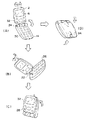
図1及び図2には、第1形態に係る携帯端末装置の斜視図が示されている。
【0013】
図1に示すように、携帯端末装置10は表示部12と操作部14が連結部18で開閉可能に連結された形状をしている。
【0014】
表示部12にはLCDで文字情報やTV、ゲーム画像などを表示できる表示板16が設けられ、全てのモードで使用する基本操作部28が設けられている。
【0015】
操作部14には、携帯端末として使用する際に必要な操作ボタン26が設けられ、表示部12が開いた状態では表示板16を見ながらボタン操作が行なえる。
【0016】
連結部18には、連結部18の中心軸24の回りに回動可能な回動部20が設けられ、中心軸24と直交する方向に回転軸22が立設されている。表示部12は回転軸22の回りに180°回動可能に支持され、収納時には表示板16の設けられた表示面32を、操作部14の操作ボタン26が設けられた操作面30と合わせて閉じることができ、また、表示部12を回動させ表示面32を外に向けて閉じることもできる。
【0017】
図2に示すように、表示部12と操作部14を開いた状態(A)から、そのまま閉じれば表示部12は背面34を外に向けて折畳まれる(D)。
【0018】
表示部12を回転軸22の回りに180°回転させ(B)、表示部と回動部を閉じると、表示面32を外に向けた状態で折畳まれる(C)。この状態ではTVやゲーム等にモードが切り替わり、基本操作部28で操作することができる。
【0019】
図3には、第1形態に係る携帯端末装置の拡大図が示されている。
【0020】
図3に示すように、表示部12を支持する回転軸22と回動部20に、表示部12の方向を検知する検出部36が設けられている。
【0021】
回転軸22の中心を貫通し表示部12を支えているシャフト42は表面が絶縁性であり、かつ外周の一部に導通部40が設けられている。一方、シャフト42を支持する回転軸22は内側面が絶縁性であり、かつ2箇所に導通部38が設けられている。
【0022】
表示部12の表示面32が外に向いた状態の時にのみ、シャフト42が回動し導通部40が回転軸22の導通部38と接触、導通する。リード線44を通じて検出部36すなわち導通部38と40の導通状態がシステム制御部50に送られ、表示部12の回動位置に応じてモード切替えの判断が行なわれる。
【0023】
リード線44が捩れないように連結部18を通すには、中心軸24を中空構造とし、開口部46を設けて中心軸24の内部にリード線44を通すようにする。
【0024】
ここではシャフト42と回転軸22に導通部38と40を設けたが、表示部12の背面34にピン等を設け、表示面30に設けたスイッチを押させる等の方法で検出してもよい。
【0025】
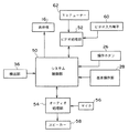
図4には、第1形態に係る携帯端末装置のブロック図が示されている。
【0026】
図4に示すように、検出部36で検出された表示部12の裏表位置に関する情報はシステム制御部50に送られ、表示板16が内側を向いていると検出された場合、携帯端末装置10は通常のモードで作動し、例えば携帯電話として機能するときは操作ボタン26から入力された電話番号に従って電話をかけ、表示板16には通話状態などの情報を表示する。通話相手の音声はオーディオ処理部54を通じてスピーカー58から出力され、使用者の音声はマイク56で拾われオーディオ処理部54を通じて信号化され、通話相手に送られる。、
一方、表示板16が外側を向いていると検出された場合は例えばTVモードに切り替わる。このときTVチューナー62から出力された映像信号はビデオ処理部52を経由してシステム制御部50へ送られ、表示板16へTV画像として出力される。同じく音声信号はTVチューナー62からシステム制御部50を経由してオーディオ処理部54へ送られ、TV音声としてスピーカー58から出力される。このとき、TVとしての操作は操作ボタン26を使用せず、表示板16と共に外側すなわち使用者側を向いている基本操作部28ですべて行なうことができる。
【0027】
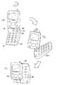
図5には、第2形態に係る携帯端末装置の斜視図が示されている。
【0028】
(A)に示すように、回動部20は連結部18の長さ方向中心にはなく、操作面30に向かって右側にオフセットしている。このため、回転軸22もまた操作面30に向かって右側にオフセットしている。
【0029】
(C)のように表示部12を180°回動させて折畳むと、操作面30は表示部12によって完全に隠れてしまわず、操作面30の向かって右側の端が使用者に向いた状態で使用できる。これにより操作ボタン26の右端の列は、折畳んで使用モードを切替えた状態でも使うことができるので、右手の親指で操作するのに好適である。。この場合、通常モードとは上下が逆になるので操作ボタン26の2ndファンクション表示も上下逆にする必要がある。
【0030】
ここでは回動部20を操作面30に向かって右側にオフセットしたが、左手での使用を優先するために左側にオフセットしていてもよい。
【0031】
【発明の効果】
本発明は上記構成としたので、使用する機能に適した形態となる形態端末装置を提供することができた。
【図面の簡単な説明】
【図1】本実施形態1に係る形態端末装置の斜視図である。
【図2】本実施形態1に係る形態端末装置の斜視図である。
【図3】本実施形態1に係る形態端末装置の拡大図である。
【図4】本実施形態1に係る形態端末装置のブロック図である。
【図5】本実施形態2に係る形態端末装置の斜視図である。
【符号の説明】
10 携帯端末装置
12 表示部
14 操作部
16 表示板
18 連結部
20 回動部
22 回転軸
24 中心軸
26 操作ボタン
28 基本操作部
30 操作面
32 表示面
34 背面
36 検出部
50 システム制御部[0001]
BACKGROUND OF THE INVENTION
The present invention relates to a portable terminal device.
[0002]
[Prior art]
Conventionally, in the case of a portable terminal device having functions such as TV screen display, moving image display, and a game machine, there has been nothing that takes a form suitable for operation according to the function.
[0003]
In particular, in a device having a large number of operation buttons such as a cellular phone, an operation unit is generally unnecessary when using functions other than the phone, and there is a greater demerit that an erroneous operation is caused by pressing the button by mistake. For example, power buttons, volume control, and CH switching are sufficient for operation buttons necessary for use as a portable TV, and it is not preferable that operation buttons that are not used are exposed to the outside. (For example, see Patent Documents 1 to 3)
Alternatively, when the mobile terminal device is configured to hide the operation unit, it is desirable to automatically switch to a function corresponding to the mode.
[0004]
[Patent Document 1]
Japanese Patent Laid-Open No. 10-257460 (
[Patent Document 2]
Japanese Patent Laid-Open No. 10-65780 (
[Patent Document 3]
JP-A-8-294030 (pages 2-5, FIGS. 1-2)
[0005]
[Problems to be solved by the invention]
In view of the above facts, an object of the present invention is to provide a form terminal device having a form suitable for a function to be used.
[0006]
[Means for Solving the Problems]
The mobile terminal device according to claim 1 is a mobile terminal device in which an image display unit that performs image display and an operation unit that performs button operation are rotatably connected by a connecting unit, and the image is connected to the connecting unit. A connecting means for connecting the display unit so that the front and back sides of the display unit can be reversed is provided.
[0007]
In the invention with the above configuration, when the image display unit and the operation unit are folded at the connection unit, the image display unit can be folded upside down and folded with the display surface facing outward, as opposed to storing. For this reason, the usage form according to the function of the image display part can be taken.
[0008]
According to a second aspect of the present invention, in the portable terminal device, the connecting portion is provided in the connecting portion so as to turn the image display portion, and the connecting portion stands in a direction orthogonal to the turning central axis of the rotating portion. And a rotating shaft that supports the image display unit so as to be rotatable by 180 °.
[0009]
In the invention with the above-described configuration, the image display unit can be rotated by 180 ° about the rotation axis that is erected from the central axis of the rotation unit that opens and closes the image display unit, so that a complicated link mechanism or the like is not used. In addition, the image display part can be turned upside down. For this reason, it is possible to easily adopt a usage pattern corresponding to the function of the image display unit.
[0010]
The portable terminal device according to
[0011]
In the invention with the above configuration, if the image display unit has the display surface facing outward when folded, it is detected and the use mode is changed. This eliminates the need for the user to change the mode by operating a changeover switch or the like.
[0012]
DETAILED DESCRIPTION OF THE INVENTION
1 and 2 are perspective views of the mobile terminal device according to the first embodiment.
[0013]
As shown in FIG. 1, the
[0014]
The
[0015]
The
[0016]
The connecting
[0017]
As shown in FIG. 2, when the
[0018]
When the
[0019]
FIG. 3 shows an enlarged view of the mobile terminal device according to the first embodiment.
[0020]
As shown in FIG. 3, a
[0021]
The
[0022]
Only when the
[0023]
In order to pass the connecting
[0024]
Here, the conducting
[0025]
FIG. 4 is a block diagram of the mobile terminal device according to the first embodiment.
[0026]
As shown in FIG. 4, information regarding the front and back positions of the
On the other hand, when it is detected that the
[0027]
FIG. 5 is a perspective view of the mobile terminal device according to the second embodiment.
[0028]
As shown to (A), the
[0029]
When the
[0030]
Here, the rotating
[0031]
【The invention's effect】
Since the present invention has the above-described configuration, a form terminal device having a form suitable for the function to be used can be provided.
[Brief description of the drawings]
FIG. 1 is a perspective view of a form terminal device according to Embodiment 1. FIG.
FIG. 2 is a perspective view of a form terminal device according to the first embodiment.
FIG. 3 is an enlarged view of a form terminal device according to the first embodiment;
FIG. 4 is a block diagram of a form terminal apparatus according to the first embodiment.
FIG. 5 is a perspective view of a form terminal device according to
[Explanation of symbols]
DESCRIPTION OF
Claims (3)
前記検知手段が前記画像表示部が前記表示面を外側に向けて折畳まれた状態であることを検知すると使用モードを変更する制御手段と、
を有することを特徴とする請求項1に記載の携帯端末装置。When the image display unit and the operation unit are folded, detection means for detecting a surface facing the outside of the display surface and the back surface of the image display unit;
Control means for changing the use mode when the detection means detects that the image display unit is folded with the display surface facing outward;
The mobile terminal device according to claim 1, comprising:
Priority Applications (1)
| Application Number | Priority Date | Filing Date | Title |
|---|---|---|---|
| JP2002282952A JP3839383B2 (en) | 2002-09-27 | 2002-09-27 | Mobile terminal device |
Applications Claiming Priority (1)
| Application Number | Priority Date | Filing Date | Title |
|---|---|---|---|
| JP2002282952A JP3839383B2 (en) | 2002-09-27 | 2002-09-27 | Mobile terminal device |
Publications (2)
| Publication Number | Publication Date |
|---|---|
| JP2004120513A true JP2004120513A (en) | 2004-04-15 |
| JP3839383B2 JP3839383B2 (en) | 2006-11-01 |
Family
ID=32276963
Family Applications (1)
| Application Number | Title | Priority Date | Filing Date |
|---|---|---|---|
| JP2002282952A Expired - Fee Related JP3839383B2 (en) | 2002-09-27 | 2002-09-27 | Mobile terminal device |
Country Status (1)
| Country | Link |
|---|---|
| JP (1) | JP3839383B2 (en) |
Cited By (10)
| Publication number | Priority date | Publication date | Assignee | Title |
|---|---|---|---|---|
| WO2005107015A1 (en) * | 2004-04-30 | 2005-11-10 | Matsushita Electric Industrial Co., Ltd. | Mobile telephone with broadcast receiver |
| KR100678137B1 (en) | 2006-02-08 | 2007-02-02 | 삼성전자주식회사 | Slim-type mobile phone with game |
| KR100689472B1 (en) | 2005-01-11 | 2007-03-08 | 삼성전자주식회사 | Portable communication device |
| EP1615408A3 (en) * | 2004-07-08 | 2007-05-23 | Sharp Kabushiki Kaisha | Foldable device with a 3d hinge having a displaced vertical axis |
| JP2008066997A (en) * | 2006-09-06 | 2008-03-21 | Sony Ericsson Mobilecommunications Japan Inc | Portable terminal |
| JP2008294375A (en) * | 2007-05-28 | 2008-12-04 | Softbank Mobile Corp | Mobile terminal |
| JP2009071870A (en) * | 2008-12-15 | 2009-04-02 | Sharp Corp | Mobile device |
| US7546150B2 (en) | 2005-01-31 | 2009-06-09 | Sharp Kabushiki Kaisha | Folding cellular phone |
| KR101218677B1 (en) * | 2005-11-07 | 2013-01-18 | 엘지전자 주식회사 | Mobile terminal and method of mode change thereof |
| US8515504B2 (en) | 2006-09-06 | 2013-08-20 | Sony Corporation | Portable terminal with rotating display |
-
2002
- 2002-09-27 JP JP2002282952A patent/JP3839383B2/en not_active Expired - Fee Related
Cited By (12)
| Publication number | Priority date | Publication date | Assignee | Title |
|---|---|---|---|---|
| WO2005107015A1 (en) * | 2004-04-30 | 2005-11-10 | Matsushita Electric Industrial Co., Ltd. | Mobile telephone with broadcast receiver |
| EP1615408A3 (en) * | 2004-07-08 | 2007-05-23 | Sharp Kabushiki Kaisha | Foldable device with a 3d hinge having a displaced vertical axis |
| US7433722B2 (en) | 2004-07-08 | 2008-10-07 | Sharp Kabushiki Kaisha | Portable device |
| KR100689472B1 (en) | 2005-01-11 | 2007-03-08 | 삼성전자주식회사 | Portable communication device |
| US7546150B2 (en) | 2005-01-31 | 2009-06-09 | Sharp Kabushiki Kaisha | Folding cellular phone |
| KR101218677B1 (en) * | 2005-11-07 | 2013-01-18 | 엘지전자 주식회사 | Mobile terminal and method of mode change thereof |
| KR100678137B1 (en) | 2006-02-08 | 2007-02-02 | 삼성전자주식회사 | Slim-type mobile phone with game |
| JP2008066997A (en) * | 2006-09-06 | 2008-03-21 | Sony Ericsson Mobilecommunications Japan Inc | Portable terminal |
| JP4619338B2 (en) * | 2006-09-06 | 2011-01-26 | ソニー・エリクソン・モバイルコミュニケーションズ株式会社 | Mobile device |
| US8515504B2 (en) | 2006-09-06 | 2013-08-20 | Sony Corporation | Portable terminal with rotating display |
| JP2008294375A (en) * | 2007-05-28 | 2008-12-04 | Softbank Mobile Corp | Mobile terminal |
| JP2009071870A (en) * | 2008-12-15 | 2009-04-02 | Sharp Corp | Mobile device |
Also Published As
| Publication number | Publication date |
|---|---|
| JP3839383B2 (en) | 2006-11-01 |
Similar Documents
| Publication | Publication Date | Title |
|---|---|---|
| JP4061473B2 (en) | Folding mobile phone | |
| EP1931118B1 (en) | Portable device consisting of three movable housing parts | |
| JP5187192B2 (en) | Mobile device | |
| JP4650997B2 (en) | Multi-function mobile phone | |
| US20090011798A1 (en) | Mobile phone | |
| JP2004007553A (en) | Mobile terminal | |
| US20080009330A1 (en) | Dual axis rotation type portable communication terminal and method for controlling the same | |
| JPWO2006038554A1 (en) | Mobile information terminal | |
| JP2007017596A (en) | Portable terminal device | |
| JP2005184841A (en) | Swivel-type mobile terminal and control method therefor | |
| JP3839383B2 (en) | Mobile terminal device | |
| JP2005198062A (en) | Folding mobile phone | |
| JP2005184267A (en) | Portable terminal | |
| JP5299273B2 (en) | Rotating portable terminal | |
| KR100651410B1 (en) | Two-way folder type terminal | |
| JPWO2007032407A1 (en) | Mobile device | |
| JP2007516628A (en) | Communication device having folding and rotatable storage member | |
| JP2003069676A (en) | Portable radio communication equipment | |
| KR100795175B1 (en) | Method for controlling function in wireless terminal | |
| JP2004120290A (en) | Portable terminal and image display method therefor | |
| JPH10257460A (en) | Portable video telephone equipment | |
| JP2004214988A (en) | Portable electronic apparatus | |
| JP2008078989A (en) | Portable equipment | |
| JP3866662B2 (en) | Foldable mobile phone | |
| JP4389114B2 (en) | Foldable portable electronic device |
Legal Events
| Date | Code | Title | Description |
|---|---|---|---|
| A621 | Written request for application examination |
Free format text: JAPANESE INTERMEDIATE CODE: A621 Effective date: 20050218 |
|
| A131 | Notification of reasons for refusal |
Free format text: JAPANESE INTERMEDIATE CODE: A131 Effective date: 20060425 |
|
| A521 | Request for written amendment filed |
Free format text: JAPANESE INTERMEDIATE CODE: A523 Effective date: 20060626 |
|
| TRDD | Decision of grant or rejection written | ||
| A01 | Written decision to grant a patent or to grant a registration (utility model) |
Free format text: JAPANESE INTERMEDIATE CODE: A01 Effective date: 20060801 |
|
| A61 | First payment of annual fees (during grant procedure) |
Free format text: JAPANESE INTERMEDIATE CODE: A61 Effective date: 20060802 |
|
| R150 | Certificate of patent or registration of utility model |
Ref document number: 3839383 Country of ref document: JP Free format text: JAPANESE INTERMEDIATE CODE: R150 Free format text: JAPANESE INTERMEDIATE CODE: R150 |
|
| FPAY | Renewal fee payment (event date is renewal date of database) |
Free format text: PAYMENT UNTIL: 20090811 Year of fee payment: 3 |
|
| S111 | Request for change of ownership or part of ownership |
Free format text: JAPANESE INTERMEDIATE CODE: R313111 |
|
| FPAY | Renewal fee payment (event date is renewal date of database) |
Free format text: PAYMENT UNTIL: 20090811 Year of fee payment: 3 |
|
| R350 | Written notification of registration of transfer |
Free format text: JAPANESE INTERMEDIATE CODE: R350 |
|
| FPAY | Renewal fee payment (event date is renewal date of database) |
Free format text: PAYMENT UNTIL: 20090811 Year of fee payment: 3 |
|
| FPAY | Renewal fee payment (event date is renewal date of database) |
Free format text: PAYMENT UNTIL: 20100811 Year of fee payment: 4 |
|
| R250 | Receipt of annual fees |
Free format text: JAPANESE INTERMEDIATE CODE: R250 |
|
| FPAY | Renewal fee payment (event date is renewal date of database) |
Free format text: PAYMENT UNTIL: 20110811 Year of fee payment: 5 |
|
| R250 | Receipt of annual fees |
Free format text: JAPANESE INTERMEDIATE CODE: R250 |
|
| FPAY | Renewal fee payment (event date is renewal date of database) |
Free format text: PAYMENT UNTIL: 20110811 Year of fee payment: 5 |
|
| FPAY | Renewal fee payment (event date is renewal date of database) |
Free format text: PAYMENT UNTIL: 20120811 Year of fee payment: 6 |
|
| R250 | Receipt of annual fees |
Free format text: JAPANESE INTERMEDIATE CODE: R250 |
|
| FPAY | Renewal fee payment (event date is renewal date of database) |
Free format text: PAYMENT UNTIL: 20120811 Year of fee payment: 6 |
|
| FPAY | Renewal fee payment (event date is renewal date of database) |
Free format text: PAYMENT UNTIL: 20130811 Year of fee payment: 7 |
|
| R250 | Receipt of annual fees |
Free format text: JAPANESE INTERMEDIATE CODE: R250 |
|
| R250 | Receipt of annual fees |
Free format text: JAPANESE INTERMEDIATE CODE: R250 |
|
| R250 | Receipt of annual fees |
Free format text: JAPANESE INTERMEDIATE CODE: R250 |
|
| R250 | Receipt of annual fees |
Free format text: JAPANESE INTERMEDIATE CODE: R250 |
|
| R250 | Receipt of annual fees |
Free format text: JAPANESE INTERMEDIATE CODE: R250 |
|
| R250 | Receipt of annual fees |
Free format text: JAPANESE INTERMEDIATE CODE: R250 |
|
| R250 | Receipt of annual fees |
Free format text: JAPANESE INTERMEDIATE CODE: R250 |
|
| R250 | Receipt of annual fees |
Free format text: JAPANESE INTERMEDIATE CODE: R250 |
|
| R250 | Receipt of annual fees |
Free format text: JAPANESE INTERMEDIATE CODE: R250 |
|
| LAPS | Cancellation because of no payment of annual fees |