【0001】
【発明の属する技術分野】
この発明は、自動車などの車両のエンジンからの排ガス中に含まれる特定の測定対象成分の重量を連続的に測定するための車載型排ガス分析装置に関する。
【0002】
【従来の技術】
【特許文献1】特開2001−124674号公報
近年、エンジン排ガス(以下、単に排ガスという)の環境負荷に対する関心が高まる中、その実態をより現実の環境に近い状態で把握しようとする動きが出てきており、路上走行中の車両から排出される窒素酸化物(NOX )、一酸化炭素(CO)、二酸化炭素(CO2 )などの成分について測定する手法の模索が行われている。この場合、前記各成分の濃度のみならず、その排出重量をも測定することが要求されるようになってきている。
【0003】上記要求を満たすものとして、前記特許文献1に記載される車載型エンジン排ガス分析装置がある。この特許文献1に記載された車載型エンジン排ガス分析装置においては、自動車内に排ガス中の成分濃度を分析する排ガス濃度分析装置を設けるとともに、この排ガス濃度分析装置による測定点の上流側から既知濃度のトレースガスを所定量注入し、排ガス中に注入されたトレースガスの注入濃度および注入流量から排ガスの流量を得るようにした排ガス流量測定装置を設け、前記排ガス濃度分析装置によって得られる成分濃度と前記排ガス流量測定装置によって得られる排ガス流量とに基づいて前記排ガス中に含まれる成分の排出重量を得るものである。
【0004】
【発明が解決しようとする課題】上記特許文献1に記載された車載型エンジン排ガス分析装置によれば、排ガス中に含まれる特定成分の濃度および重量を連続的に測定することができる。しかしながら、車載型エンジン排ガス分析計においては、排ガス流量測定装置によって排ガス流量を測定するのに、トレースガス源を車両内に搭載し、トレースガスを排気管内にその適宜位置から測定しながら注入する必要があり、それだけ、排ガス流量測定のための構成が複雑になるといった問題がある。また、上記排ガス流量測定装置においては、排ガス濃度分析装置と組み合わせた場合、前記両装置における時間軸のずれや応答差の問題があり、必ずしも正確な流量値が得られないことがあり、そのため、排ガス中に含まれる特定の測定対象成分の重量を精度よく求められないことがあった。
【0005】この発明は、上述の事柄に留意してなされたもので、その目的は、実際の道路を走行中の車両においてその排ガス中に含まれる特定の測定対象成分の重量を、簡便な構成でありながらも精度よく連続的に測定することのできる車載型排ガス分析装置を提供することである。
【0006】
【課題を解決するための手段】上記目的を達成するため、この発明の車載型排ガス分析装置は、エンジンに連なる排気管内を流れる排ガスの流量を測定するピトー管式流量計、前記排ガス中の測定対象成分の濃度を測定する排ガス濃度測定装置と演算処理部とを車両に搭載するとともに、前記演算処理部において、前記ピトー管式流量計および排ガス濃度測定装置のそれぞれの出力信号並びに排ガス温度信号および排ガス圧力信号を用いて、前記測定対象成分の排出重量を連続的に求めるようにしたことを特徴としている(請求項1)。
【0007】上記車載型排ガス分析装置によれば、車内にトレースガス源や注入されるトレースガスの量を測定する装置などを設ける必要がなく、簡便な構成で排ガス中に含まれる特定の測定対象成分の重量を精度よく連続的に測定することができる。
【0008】そして、上記請求項1に記載の車載型排ガス分析装置において、ピトー管式流量計の静圧検出用ピトー管および動圧検出用ピトー管と差圧計との間にバッファタンクを設けるようにしてもよい(請求項2)。この構成によれば、排気管内を流れる排ガスが脈動しても、これに起因して変動する圧力の変動分がバッファタンクによって除去されるので、前記脈動の影響を巧みに除去することができ、排ガスの流量を精度よく測定することができる。
【0009】また、上記請求項1または2に記載の車載型排ガス分析装置において、排気管に対して接続・分離自在のアダプタ管に静圧検出用ピトー管および動圧検出用ピトー管を設けるようにしてもよい(請求項3)。この構成によれば、静圧検出用ピトー管および動圧検出用ピトー管の取り扱いがきわめて簡単になり、これら部材の排気管への装着・分離をきわめて容易に行うことができる。
【0010】
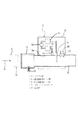
【発明の実施の形態】以下、この発明の詳細を、図を参照しながら説明する。図1〜図3は、この発明の車載型排ガス分析装置の一例を示すものである。まず、図1は、車載型排ガス分析装置を自動車に搭載した実施の形態を示し、この図において、1は測定に供される車両としての自動車である。2はこの自動車1のエンジン、3はエンジン2に連なり排ガスGが流れる排気管、4は排気管3に設けられる触媒装置である。5は例えば路面である。
【0011】そして、6は自動車1内に設けられる排ガス濃度測定装置としてのNDIR型ガス分析装置で、ガス分析部6Aと演算制御部6Bとからなる。より詳しくは、図2の示すように、前記排気管3の例えば触媒装置4より下流側に、ガス分岐部7およびガス合流部8が設けられ、これらのガス分岐部7とガス合流部8とを結ぶガス流路9にガス分析部6Aが介装されている。前記ガス分岐部7は、排気管3を流れてくるエンジン2からの排ガスGの一部をサンプルガスとして採取できるように構成されている。そして、前記ガス流路9のガス分岐部7とガス分析部6Aとの間にはヒータ10が巻設してあり、これを流れるサンプルガスが所定の温度に加熱保温されるようにしてある。そして、前記ガス分析部6Aは、その詳細な構成の図示は省略するが、排ガスGの一部がサンプルガスとして連続的に供給されるセルの一端に赤外光源を設け、他端に光チョッパを介して複数の測定対象成分、例えばHC、COや干渉成分としてのH2 Oの濃度をそれぞれ検出するための検出部を備えてなるものである。また、演算制御部6Bは、自動車1内の演算処理装置(後述する)からの指令によりガス分析部6Aの各部を制御したり、ガス分析部6Aの検出部の出力信号に基づいて濃度演算を行うように構成されている。
【0012】また、11はエンジン2からの排ガスGが流れる排気管3の最下流端に着脱自在に設けられ、前記排ガスGの流量を測定するピトー管式流量計で、例えば図2および図3に示すように構成されている。すなわち、これらの図において、12は排気管3の下流端部3aに分離自在に接続されるアダプタ管で、排気管3と同等の内径を有し、その一端側には、固定ねじ13を備え前記下流端部3aに着脱自在に外嵌される接続部14が形成され、他端側は開放されている。そして、このアダプタ管12には、ピトー管式流量計11がユニット構成された状態で設けられている。すなわち、アダプタ管12の上流側位置の管壁12aに管内部を臨むように静圧検出用ピトー管15が設けられ、この静圧検出用ピトー管15のやや下流側に管内に挿入されるようにして動圧検出用ピトー管16が設けられている。これらのピトー管15,16は、それぞれ、バッファタンク17,18を介して差圧計19に接続されている。また、20,21は動圧検出用ピトー管16の下流側のアダプタ管12の管内に挿入されるようにして設けられる温度センサ、圧力センサで、それぞれ排ガスGの温度および圧力を測定するもので、これらの出力信号はインタ−フェース24(後述する)を介して演算処理装置23(後述する)に入力される。さらに、22は前記各部材15〜21を収納するケースで、アダプタ管12に適宜の手段で着脱自在に取り付けられている。
【0013】さらに、23は自動車1の内部に搭載される演算処理装置(例えばパソコンなど)で、前記演算制御部6Bとの間で信号を授受してNDIR型ガス分析装置6全体を制御したり、演算制御部6Bおよびピトー管式流量計11からの信号に基づいて演算を行って、エンジン2から排出されるHC、CO等の特定の測定対象成分の重量Mx (t)を算出したり、各種の測定結果などを表示したり、測定結果などをデータとして格納する。なお、24はピトー管式流量計11と演算処理装置19との間に介装されるインタ−フェースで、アナログ信号をディジタル信号に変換する機能などを備えている。また、前記演算処理装置19には、自動車1における車速やエンジン回転数などの車両データも送られるようにしてある。
【0014】ここで、前記ピトー管式流量計11による排ガス流量およびNDIR型ガス分析装置6による特定の測定対象成分の濃度を用いて、特定の成分xの総排出重量を求めるための式は、下記の通りである。
まず、排ガス流量(標準状態換算)Qexh (t)〔m3 /min〕は下記(1)式で表される。
Qexh (t)=K×{Pexh (t)/101.3}×{293.15/Texh (t)}×√{Δh(t)/γexh } ……(1)
ここで、 K:比例係数
Pexh (t):排ガス圧力〔κPa〕
Texh (t):排ガス温度〔K〕
Δh(t):ピトー管の差圧
γexh :標準状態における排ガス密度〔g/m3 〕
すなわち、比例係数Kを予め求めておけば、排ガスGの温度、圧力、ピトー管の差圧の測定値から、排ガス流量を得ることができる。
次に、測定対象成分の時系列排出重量は、排出濃度、および排ガス流量、各測定対象成分の密度から算出される。すなわち、成分xの排出重量(時系列)〔g/s〕および成分xの総排出重量Mxtotal 〔g/km〕は、それぞれ、下記(2),(3)で表される。
Mx (t)=Cx (t)×10−6×{Qexh (t)/60}×γx ……(2)
Mx total =Σ{Mx (t)/L} ……(3)
ここで、 Cx (t):成分xの排出濃度(時系列)〔ppm/ppmC〕
Qexh (t):排ガス流量(標準状態換算)〔m3 /min〕
γx :成分xの標準状態における密度〔g/m3 〕
L:車両走行距離〔km〕
【0015】上述のように構成された車載型エンジン排ガス分析装置においては、エンジン2からの排ガスGの一部が排気管3のガス分岐部7においてサンプリングされてNDIR型ガス分析装置6のガス分析部6Aに連続的に供給されることにより、排ガスG中に含まれるHC、COの濃度が測定される。前記ガス分析部6Aに供給された排ガスGの一部は、前記ガス分岐部7においてサンプリングされなかった大部分の排ガスGと排気管3のガス合流部8において合流し、この合流後の排ガスGは、排気管6の下流端に接続されたアダプタ管12に設けられたピトー管式流量計11に向かって流れる。
【0016】前記ピトー管式流量計11においては、静圧検出用ピトー管15によって、排気管3を経てアダプタ管12内を流れる排ガスGの静圧が得られ、動圧検出用ピトー管16によって、前記排ガスGの動圧と静圧の和が得られる。そして、差圧計19において、前記静圧検出用ピトー管15による検出圧力と、動圧検出用ピトー管16による検出圧力との差をとることにより、排ガスGの動圧が得られ、これに基づいて演算を行うことにより排ガスGの流量が得られる。そして、この場合、静圧検出用ピトー管15および動圧検出用ピトー管16による圧力を、それぞれ、バッファタンク17,18を介して差圧計19に入力するようにしているので、前記排ガスGが脈動を生じても、これに起因して変動する圧力の変動分がバッファタンク17,19によってそれぞれ除去されるので、排ガスGの流量変化によって生ずる圧力差のみ取り出すことができ、エンジン2の出力の変動に起因して排ガスGに脈動が生じていても、これの影響を巧みに除去することができ、排ガスGの流量を精度よく測定することができる。
【0017】上述のように、この実施の形態における車載型エンジン排ガス分析装置においては、NDIR型ガス分析装置6によって、エンジン2から排出される排ガスG中に含まれるHC、CO等の濃度を連続測定することができるとともに、ピトー管式流量計11によって、前記排ガスGの流量を連続測定することができる。したがって、前記HC、CO濃度および排ガス流量からエンジン2から排出されるHC、COの重量を連続的に演算により求めることができる。
【0018】そして、上記ピトー管式流量計11は、自動車1のエンジン2に連なる排気管3に対して接続・分離自在なアダプタ管12に形成されるものであり、小型・コンパクトである。しかも、静圧検出用ピトー管15および動圧検出用ピトー管16と差圧計19との間にバッファタンク17,18を設けたものであるから、排気管3を流れる排ガスGに脈動を生じても、これの影響を大きく受けることなく排ガスGの流量を高精度に連続測定することができる。
【0019】図4および図5は、ピトー管式流量計11において、バッファタンク17,18を設けていないときと設けたときにおける流量測定結果を示すものである。これらの図において、符号Aで示すグラフは、ピトー管式流量計11の測定結果であり、符号Bで示すグラフは、図比較例としてのSAO(Smooth Approch Orifice)を用いた流量計の測定結果である。そして、使用した自動車1は、排気量2Lのガソリン車である。そして、図4、図5のいずれにおいても、(B)は(A)の部分拡大図である。
【0020】図4は、バッファタンク17,18を設けていないときの流量変化を示すもので、図4(A)に示すグラフa,bでは、ほとんど両グラフa,bに差がないように見えるが、同図(B)に示すように拡大してみると、両グラフa,bにはかなりの差があることがわかる。
【0021】図5は、バッファタンク17,18を設けたときの流量変化を示すもので、両グラフa,bには全くといってよいほど差が見られない。
【0022】
【発明の効果】以上説明したように、この発明の車載型排ガス分析装置は、エンジンに連なる排気管内を流れる排ガスの流量を測定するピトー管式流量計と前記排ガス中の測定対象成分の濃度を測定する排ガス濃度測定装置と演算処理部とを車両に搭載するとともに、前記演算処理部において、前記ピトー管式流量計および排ガス濃度測定装置のそれぞれの出力信号並びに排ガス温度信号および排ガス圧力信号を用いて、前記測定対象成分の排出重量を連続的に求めるようにしているので、車内にトレースガス源や注入されるトレースガスの量を測定する装置などを設ける必要がなく、簡便な構成で排ガス中に含まれる特定の測定対象成分の重量を精度よく連続的に測定することができる。
【0023】そして、前記ピトー管式流量計における静圧検出用ピトー管および動圧検出用ピトー管と差圧計との間にバッファタンクを設けた場合には、排気管内を流れる排ガスに脈動を生じても、これに起因して変動する圧力の変動分がバッファタンクによって除去されるので、前記脈動の影響を巧みに除去することができ、排ガスの流量を精度よく測定することができる。また、排気管に対して接続・分離自在のアダプタ管に静圧検出用ピトー管および動圧検出用ピトー管を設けるようにした場合には、これらの部材の取り扱いがきわめて簡単になり、排気管への装着・分離をきわめて容易に行うことができる。
【図面の簡単な説明】
【図1】この発明の車載型排ガス分析装置を自動車に搭載した状態を概略的に示す図である。
【図2】前記車載型排ガス分析装置の構成の一例を概略的に示す図である。
【図3】前記車載型排ガス分析装置で用いるピトー管式流量計の排気管への取り付け構造の一例を概略的に示す図である。
【図4】前記車載型排ガス分析装置において、バッファタンクを設けないときの流量測定結果を示す図である。
【図5】前記車載型排ガス分析装置において、バッファタンクを設けたときの流量測定結果を示す図である。
【符号の説明】1…車両、2…エンジン、3…排気管、6…排ガス濃度測定装置、11…ピトー管式流量計、12…アダプタ管、15…静圧検出用ピトー管、16…動圧検出用ピトー管、17,18…バッファタンク、19…差圧計、23…演算処理部、G…排ガス。[0001]
TECHNICAL FIELD OF THE INVENTION
The present invention relates to an on-vehicle exhaust gas analyzer for continuously measuring the weight of a specific measurement target component contained in exhaust gas from an engine of a vehicle such as an automobile.
[0002]
[Prior art]
[Patent Document 1] Japanese Patent Application Laid-Open No. 2001-124677 In recent years, as interest in the environmental load of engine exhaust gas (hereinafter simply referred to as exhaust gas) has increased, there has been a movement to grasp the actual situation in a state closer to the real environment. and have, nitrogen oxide exhausted from a vehicle in road (NO X), carbon monoxide (CO), the search for techniques of measuring the components such as carbon dioxide (CO 2) is being performed. In this case, it has been required to measure not only the concentrations of the respective components but also the discharged weight.
[0003] A vehicle-mounted engine exhaust gas analyzer described in Patent Document 1 satisfies the above requirements. In the vehicle-mounted engine exhaust gas analyzer described in Patent Document 1, an exhaust gas concentration analyzer for analyzing the concentration of components in exhaust gas is provided in a vehicle, and a known concentration is measured from an upstream side of a measurement point by the exhaust gas concentration analyzer. A predetermined amount of the trace gas is injected, and an exhaust gas flow rate measuring device is provided to obtain the flow rate of the exhaust gas from the injection concentration and the injection flow rate of the trace gas injected into the exhaust gas, and the component concentration obtained by the exhaust gas concentration analyzer. The exhausted weight of the component contained in the exhaust gas is obtained based on the exhaust gas flow rate obtained by the exhaust gas flow measuring device.
[0004]
According to the vehicle-mounted engine exhaust gas analyzer described in Patent Document 1, the concentration and weight of a specific component contained in exhaust gas can be continuously measured. However, in the case of a vehicle-mounted engine exhaust gas analyzer, in order to measure the exhaust gas flow rate using an exhaust gas flow rate measuring device, it is necessary to mount a trace gas source in the vehicle and inject the trace gas into the exhaust pipe while measuring it from an appropriate position. However, there is a problem that the configuration for measuring the exhaust gas flow rate becomes complicated. In addition, in the exhaust gas flow rate measuring device, when combined with an exhaust gas concentration analyzer, there is a problem of a time axis shift and a response difference between the two devices, and may not always obtain an accurate flow rate value, In some cases, the weight of a specific component to be measured contained in the exhaust gas cannot be accurately determined.
The present invention has been made in consideration of the above-mentioned matters, and an object of the present invention is to determine the weight of a specific measurement target component contained in exhaust gas of a vehicle traveling on an actual road by a simple configuration. However, it is an object of the present invention to provide a vehicle-mounted exhaust gas analyzer capable of continuously measuring with high accuracy.
[0006]
In order to achieve the above object, an on-vehicle exhaust gas analyzer according to the present invention comprises a pitot tube flow meter for measuring the flow rate of exhaust gas flowing in an exhaust pipe connected to an engine; An exhaust gas concentration measurement device for measuring the concentration of the target component and an arithmetic processing unit are mounted on the vehicle, and in the arithmetic processing unit, an output signal and an exhaust gas temperature signal of the pitot tube flow meter and the exhaust gas concentration measurement device, respectively. The exhaust gas pressure signal is used to continuously calculate the exhausted weight of the component to be measured (claim 1).
According to the above-mentioned on-board type exhaust gas analyzer, there is no need to provide a trace gas source or a device for measuring the amount of trace gas to be injected in the vehicle. The weight of the components can be continuously measured with high accuracy.
In the above-mentioned on-vehicle exhaust gas analyzer, a buffer tank may be provided between the pitot tube for static pressure detection and the pitot tube for dynamic pressure detection of the pitot tube flow meter and the differential pressure gauge. (Claim 2). According to this configuration, even when the exhaust gas flowing in the exhaust pipe pulsates, the fluctuation in the pressure that fluctuates due to the pulsation is removed by the buffer tank, so that the influence of the pulsation can be skillfully removed, The flow rate of the exhaust gas can be accurately measured.
Further, in the vehicle-mounted exhaust gas analyzer according to the first or second aspect, a pitot tube for detecting a static pressure and a pitot tube for detecting a dynamic pressure are provided on an adapter tube which can be connected to and separated from the exhaust pipe. (Claim 3). According to this configuration, the handling of the pitot tube for detecting the static pressure and the pitot tube for detecting the dynamic pressure becomes extremely simple, and the attachment and separation of these members to and from the exhaust pipe can be performed very easily.
[0010]
DETAILED DESCRIPTION OF THE PREFERRED EMBODIMENTS The details of the present invention will be described below with reference to the drawings. 1 to 3 show an example of a vehicle-mounted exhaust gas analyzer according to the present invention. First, FIG. 1 shows an embodiment in which a vehicle-mounted exhaust gas analyzer is mounted on an automobile. In this figure, reference numeral 1 denotes an automobile as a vehicle used for measurement. Reference numeral 2 denotes an engine of the automobile 1, reference numeral 3 denotes an exhaust pipe connected to the engine 2 and through which exhaust gas G flows, and reference numeral 4 denotes a catalyst device provided in the exhaust pipe 3. 5 is a road surface, for example.
Reference numeral 6 denotes an NDIR type gas analyzer as an exhaust gas concentration measuring device provided in the automobile 1, which comprises a gas analyzer 6A and a calculation controller 6B. More specifically, as shown in FIG. 2, a gas branch portion 7 and a gas merge portion 8 are provided downstream of the exhaust pipe 3, for example, from the catalyst device 4. A gas analyzer 6A is interposed in a gas flow path 9 connecting the two. The gas branch section 7 is configured so that a part of the exhaust gas G from the engine 2 flowing through the exhaust pipe 3 can be collected as a sample gas. A heater 10 is wound between the gas branching section 7 of the gas flow path 9 and the gas analyzing section 6A so that the sample gas flowing therethrough is heated and kept at a predetermined temperature. The gas analyzer 6A is provided with an infrared light source at one end of a cell to which a part of the exhaust gas G is continuously supplied as a sample gas, and an optical chopper at the other end. And a detection unit for detecting the concentration of each of a plurality of components to be measured, for example, HC, CO, and H 2 O as an interference component, via the interface. The arithmetic control unit 6B controls each unit of the gas analysis unit 6A according to a command from an arithmetic processing unit (described later) in the automobile 1, and performs a concentration calculation based on an output signal of a detection unit of the gas analysis unit 6A. Is configured to do so.
Reference numeral 11 denotes a pitot tube type flow meter which is detachably provided at the most downstream end of the exhaust pipe 3 through which the exhaust gas G from the engine 2 flows, and which measures the flow rate of the exhaust gas G. For example, FIGS. It is configured as shown in FIG. That is, in these figures, reference numeral 12 denotes an adapter pipe detachably connected to the downstream end 3a of the exhaust pipe 3, which has an inner diameter equivalent to that of the exhaust pipe 3, and has a fixing screw 13 at one end thereof. A connection portion 14 is formed on the downstream end 3a so as to be detachably fitted to the outside, and the other end is open. The adapter tube 12 is provided with the pitot tube flow meter 11 in a unit configuration. That is, the pitot tube 15 for static pressure detection is provided so as to face the inside of the tube on the tube wall 12a at the upstream position of the adapter tube 12, and is inserted into the tube slightly downstream of the pitot tube 15 for static pressure detection. A pitot tube 16 for detecting dynamic pressure is provided. These pitot tubes 15, 16 are connected to a differential pressure gauge 19 via buffer tanks 17, 18, respectively. Reference numerals 20 and 21 denote a temperature sensor and a pressure sensor which are provided so as to be inserted into the adapter tube 12 on the downstream side of the pitot tube 16 for detecting dynamic pressure, and respectively measure the temperature and the pressure of the exhaust gas G. These output signals are input to an arithmetic processing unit 23 (to be described later) via an interface 24 (to be described later). Reference numeral 22 denotes a case for accommodating the members 15 to 21. The case 22 is detachably attached to the adapter tube 12 by appropriate means.
Further, reference numeral 23 denotes an arithmetic processing unit (for example, a personal computer) mounted inside the automobile 1, which exchanges signals with the arithmetic control unit 6B to control the entire NDIR type gas analyzer 6. , And calculates the weight M x (t) of specific measurement target components such as HC and CO discharged from the engine 2 by performing calculations based on signals from the calculation control unit 6B and the pitot tube flow meter 11. And displays various measurement results and stores the measurement results as data. An interface 24 is provided between the pitot tube flow meter 11 and the arithmetic processing unit 19 and has a function of converting an analog signal into a digital signal. Further, vehicle data such as the vehicle speed and the engine speed of the automobile 1 are also sent to the arithmetic processing unit 19.
Here, using the exhaust gas flow rate by the pitot tube flow meter 11 and the concentration of a specific component to be measured by the NDIR type gas analyzer 6, an equation for calculating the total discharge weight of the specific component x is as follows: It is as follows.
First, the exhaust gas flow rate (converted to standard state) Q exh (t) [m 3 / min] is represented by the following equation (1).
Q exh (t) = K × {P exh (t) /101.3} × {293.15 / T exh (t)} × {Δh (t) / γ exh } (1)
Here, K: proportional coefficient P exh (t): exhaust gas pressure [κPa]
T exh (t): Exhaust gas temperature [K]
Δh (t): differential pressure of pitot tube γ exh : exhaust gas density in standard condition [g / m 3 ]
That is, if the proportional coefficient K is determined in advance, the exhaust gas flow rate can be obtained from the measured values of the temperature and pressure of the exhaust gas G and the differential pressure of the pitot tube.
Next, the time-series emission weight of the measurement target component is calculated from the emission concentration, the exhaust gas flow rate, and the density of each measurement target component. That is, the discharge weight (time series) [g / s] of the component x and the total discharge weight Mx total [g / km] of the component x are represented by the following (2) and (3), respectively.
M x (t) = C x (t) × 10 −6 × {Q exh (t) / 60} × γ x (2)
M x total = {M x (t) / L} (3)
Here, C x (t): emission concentration of component x (time series) [ppm / ppmC]
Q exh (t): Exhaust gas flow rate (converted to standard state) [m 3 / min]
γ x : density of the component x in the standard state [g / m 3 ]
L: Vehicle traveling distance [km]
In the vehicle-mounted engine exhaust gas analyzer configured as described above, a part of the exhaust gas G from the engine 2 is sampled in the gas branch section 7 of the exhaust pipe 3 and the NDIR type gas analyzer 6 analyzes the gas. By being continuously supplied to the section 6A, the concentrations of HC and CO contained in the exhaust gas G are measured. Part of the exhaust gas G supplied to the gas analyzer 6A merges with most of the exhaust gas G not sampled in the gas branching unit 7 at the gas junction 8 of the exhaust pipe 3, and the exhaust gas G after the merger. Flows toward a pitot tube flow meter 11 provided in an adapter tube 12 connected to the downstream end of the exhaust pipe 6.
In the pitot tube flow meter 11, the static pressure of the exhaust gas G flowing through the exhaust pipe 3 through the adapter pipe 12 is obtained by the pitot pipe 15 for static pressure detection. Thus, the sum of the dynamic pressure and the static pressure of the exhaust gas G is obtained. Then, by taking the difference between the pressure detected by the static pressure detection pitot tube 15 and the pressure detected by the dynamic pressure detection pitot tube 16 in the differential pressure gauge 19, the dynamic pressure of the exhaust gas G is obtained. By performing the calculation, the flow rate of the exhaust gas G is obtained. In this case, the pressures from the pitot tube 15 for static pressure detection and the pitot tube 16 for dynamic pressure detection are input to the differential pressure gauge 19 via the buffer tanks 17 and 18, respectively. Even if pulsation occurs, the fluctuations in pressure that fluctuate due to the pulsation are removed by the buffer tanks 17 and 19, respectively, so that only the pressure difference caused by the change in the flow rate of the exhaust gas G can be taken out, and the output of the engine 2 can be taken out. Even if the pulsation occurs in the exhaust gas G due to the fluctuation, the influence thereof can be skillfully removed, and the flow rate of the exhaust gas G can be accurately measured.
As described above, in the vehicle-mounted engine exhaust gas analyzer according to this embodiment, the concentration of HC, CO, etc. contained in the exhaust gas G discharged from the engine 2 is continuously measured by the NDIR type gas analyzer 6. The flow rate of the exhaust gas G can be continuously measured by the pitot tube flow meter 11 while the flow rate can be measured. Therefore, the weights of HC and CO discharged from the engine 2 can be continuously calculated from the HC and CO concentrations and the exhaust gas flow rate.
The pitot tube flow meter 11 is formed in an adapter tube 12 which can be connected to and separated from the exhaust pipe 3 connected to the engine 2 of the automobile 1, and is small and compact. Moreover, since the buffer tanks 17 and 18 are provided between the static pressure detection pitot tube 15 and the dynamic pressure detection pitot tube 16 and the differential pressure gauge 19, the exhaust gas G flowing through the exhaust pipe 3 pulsates. Also, the flow rate of the exhaust gas G can be continuously measured with high accuracy without being greatly affected by this.
FIGS. 4 and 5 show flow rate measurement results when the buffer tanks 17 and 18 are not provided and when the pitot tube flow meter 11 is provided. In these figures, the graphs indicated by the symbol A are the measurement results of the Pitot tube flowmeter 11, and the graphs indicated by the symbol B are the measurement results of the flow meter using SAO (Smooth Approch Origin) as a diagram comparative example. It is. The used automobile 1 is a gasoline vehicle having a displacement of 2 L. 4B and 5B, (B) is a partially enlarged view of (A).
FIG. 4 shows the flow rate change when the buffer tanks 17 and 18 are not provided. In the graphs a and b shown in FIG. 4A, there is almost no difference between the graphs a and b. As can be seen, when enlarged as shown in FIG. 7B, it can be seen that there is a considerable difference between the two graphs a and b.
FIG. 5 shows the flow rate change when the buffer tanks 17 and 18 are provided, and there is almost no difference between the two graphs a and b.
[0022]
As described above, the vehicle-mounted exhaust gas analyzer according to the present invention comprises a pitot tube flow meter for measuring the flow rate of exhaust gas flowing in an exhaust pipe connected to an engine and a concentration of a component to be measured in the exhaust gas. The exhaust gas concentration measurement device to be measured and the arithmetic processing unit are mounted on the vehicle, and the arithmetic processing unit uses the respective output signals of the pitot tube flow meter and the exhaust gas concentration measurement device, and the exhaust gas temperature signal and the exhaust gas pressure signal. Therefore, since the exhausted weight of the measurement target component is continuously obtained, there is no need to provide a trace gas source or a device for measuring the amount of the trace gas to be injected in the vehicle, and the exhaust gas can be easily measured with a simple configuration. , The weight of the specific component to be measured contained in can be continuously measured with high accuracy.
When a buffer tank is provided between the pitot tube for static pressure detection and the pitot tube for dynamic pressure detection and the differential pressure gauge in the pitot tube flow meter, pulsation occurs in the exhaust gas flowing through the exhaust pipe. However, since the fluctuation of the pressure that fluctuates due to this is removed by the buffer tank, the influence of the pulsation can be skillfully removed, and the flow rate of the exhaust gas can be accurately measured. If the pitot tube for static pressure detection and the pitot tube for dynamic pressure detection are provided on an adapter tube that can be freely connected to and separated from the exhaust pipe, the handling of these members becomes extremely simple, and the exhaust pipe Mounting / separation to / from the device can be performed very easily.
[Brief description of the drawings]
FIG. 1 is a diagram schematically showing a state where a vehicle-mounted exhaust gas analyzer of the present invention is mounted on an automobile.
FIG. 2 is a diagram schematically showing an example of the configuration of the on-vehicle exhaust gas analyzer.
FIG. 3 is a view schematically showing an example of a structure for mounting a pitot tube flow meter used in the on-vehicle exhaust gas analyzer to an exhaust pipe.
FIG. 4 is a diagram showing a flow rate measurement result when no buffer tank is provided in the on-vehicle exhaust gas analyzer.
FIG. 5 is a view showing a flow rate measurement result when a buffer tank is provided in the on-vehicle exhaust gas analyzer.
[Description of Signs] 1 ... Vehicle, 2 ... Engine, 3 ... Exhaust pipe, 6 ... Exhaust gas concentration measuring device, 11 ... Pitot pipe flow meter, 12 ... Adapter pipe, 15 ... Pitot pipe for static pressure detection, 16 ... Driving Pitot tube for pressure detection, 17, 18: buffer tank, 19: differential pressure gauge, 23: arithmetic processing unit, G: exhaust gas.