JP2004116523A - Control method and device for internal combustion engine - Google Patents
Control method and device for internal combustion engine Download PDFInfo
- Publication number
- JP2004116523A JP2004116523A JP2003330253A JP2003330253A JP2004116523A JP 2004116523 A JP2004116523 A JP 2004116523A JP 2003330253 A JP2003330253 A JP 2003330253A JP 2003330253 A JP2003330253 A JP 2003330253A JP 2004116523 A JP2004116523 A JP 2004116523A
- Authority
- JP
- Japan
- Prior art keywords
- data
- actuator
- control device
- data carrier
- internal combustion
- Prior art date
- Legal status (The legal status is an assumption and is not a legal conclusion. Google has not performed a legal analysis and makes no representation as to the accuracy of the status listed.)
- Pending
Links
Images

Classifications
-
- F—MECHANICAL ENGINEERING; LIGHTING; HEATING; WEAPONS; BLASTING
- F02—COMBUSTION ENGINES; HOT-GAS OR COMBUSTION-PRODUCT ENGINE PLANTS
- F02D—CONTROLLING COMBUSTION ENGINES
- F02D41/00—Electrical control of supply of combustible mixture or its constituents
- F02D41/24—Electrical control of supply of combustible mixture or its constituents characterised by the use of digital means
- F02D41/2406—Electrical control of supply of combustible mixture or its constituents characterised by the use of digital means using essentially read only memories
- F02D41/2425—Particular ways of programming the data
- F02D41/2429—Methods of calibrating or learning
- F02D41/2432—Methods of calibration
- F02D41/2435—Methods of calibration characterised by the writing medium, e.g. bar code
-
- F—MECHANICAL ENGINEERING; LIGHTING; HEATING; WEAPONS; BLASTING
- F02—COMBUSTION ENGINES; HOT-GAS OR COMBUSTION-PRODUCT ENGINE PLANTS
- F02D—CONTROLLING COMBUSTION ENGINES
- F02D41/00—Electrical control of supply of combustible mixture or its constituents
- F02D41/24—Electrical control of supply of combustible mixture or its constituents characterised by the use of digital means
- F02D41/2406—Electrical control of supply of combustible mixture or its constituents characterised by the use of digital means using essentially read only memories
- F02D41/2425—Particular ways of programming the data
- F02D41/2429—Methods of calibrating or learning
- F02D41/2451—Methods of calibrating or learning characterised by what is learned or calibrated
- F02D41/2464—Characteristics of actuators
- F02D41/2467—Characteristics of actuators for injectors
- F02D41/247—Behaviour for small quantities
-
- F—MECHANICAL ENGINEERING; LIGHTING; HEATING; WEAPONS; BLASTING
- F02—COMBUSTION ENGINES; HOT-GAS OR COMBUSTION-PRODUCT ENGINE PLANTS
- F02D—CONTROLLING COMBUSTION ENGINES
- F02D41/00—Electrical control of supply of combustible mixture or its constituents
- F02D41/20—Output circuits, e.g. for controlling currents in command coils
- F02D2041/202—Output circuits, e.g. for controlling currents in command coils characterised by the control of the circuit
- F02D2041/2024—Output circuits, e.g. for controlling currents in command coils characterised by the control of the circuit the control switching a load after time-on and time-off pulses
-
- F—MECHANICAL ENGINEERING; LIGHTING; HEATING; WEAPONS; BLASTING
- F02—COMBUSTION ENGINES; HOT-GAS OR COMBUSTION-PRODUCT ENGINE PLANTS
- F02D—CONTROLLING COMBUSTION ENGINES
- F02D41/00—Electrical control of supply of combustible mixture or its constituents
- F02D41/20—Output circuits, e.g. for controlling currents in command coils
- F02D2041/202—Output circuits, e.g. for controlling currents in command coils characterised by the control of the circuit
- F02D2041/2058—Output circuits, e.g. for controlling currents in command coils characterised by the control of the circuit using information of the actual current value
-
- F—MECHANICAL ENGINEERING; LIGHTING; HEATING; WEAPONS; BLASTING
- F02—COMBUSTION ENGINES; HOT-GAS OR COMBUSTION-PRODUCT ENGINE PLANTS
- F02D—CONTROLLING COMBUSTION ENGINES
- F02D41/00—Electrical control of supply of combustible mixture or its constituents
- F02D41/24—Electrical control of supply of combustible mixture or its constituents characterised by the use of digital means
- F02D41/2406—Electrical control of supply of combustible mixture or its constituents characterised by the use of digital means using essentially read only memories
- F02D41/2425—Particular ways of programming the data
- F02D41/2487—Methods for rewriting
Abstract
Description
本発明は、制御装置により少なくとも1つのアクチュエータに配属されたデータ担体からデータが読み出されて制御に使用され、ここでデータ担体は当該のアクチュエータを表すデータを含む内燃機関の制御方法および装置に関する。 The invention relates to a method and a device for controlling an internal combustion engine, in which data is read from a data carrier assigned to at least one actuator by a control device and used for control, wherein the data carrier contains data representing the actuator. .
制御装置がデータ担体からデータを読み出して制御に使用する内燃機関の制御方法および制御装置が知られている。ここでデータ担体は少なくとも1つのアクチュエータに配属されており、このアクチュエータを表すデータを含んでいる。例えば駆動信号に依存して内燃機関に燃料を調量するインジェクタに対して、個々のインジェクタのエラーを補償する補正値を含むデータ担体がともに動作する。 There are known a control method and a control device for an internal combustion engine in which a control device reads data from a data carrier and uses the data for control. Here, the data carrier is assigned to at least one actuator and contains data representing this actuator. For example, for injectors which meter fuel to the internal combustion engine as a function of the drive signal, a data carrier containing correction values for compensating for the errors of the individual injectors operates together.
このとき補正データはインジェクタの製造終了間際に求められ、データ担体内へ読み込まれる。その際にデータ担体はバーコードまたは読み出し専用のメモリエレメントとして構成することができる。制御装置の最初の初期化時にこのデータが制御装置内へ読み込まれ、後の駆動において内燃機関の制御に用いられる。 At this time, the correction data is obtained immediately before the end of the manufacture of the injector, and is read into the data carrier. The data carrier can be configured as a barcode or a read-only memory element. This data is read into the control device during the initial initialization of the control device and is used for controlling the internal combustion engine in a later drive.
こんにちの制御装置は同様にインジェクタに対応させるべき補正値を求める種々の機能部を有している。この機能部には例えばゼロ量補正部がある。これに対するデータは通常の場合制御装置内に格納され、内燃機関の制御に用いられる。 The control device of the present invention also has various functional units for determining correction values to be made to correspond to the injectors. This function unit includes, for example, a zero amount correction unit. The data for this is usually stored in the control unit and used for controlling the internal combustion engine.
通常の場合、インジェクタの個別噴射量は複数の検査ポイントで検出される。この場合それぞれの噴射量は目標値から偏差して求められる。これらのデータはインジェクタの完成時に適切な形式でインジェクタに添付される。機関組み込み時および/または車両の組み立て時に適切なシステム、例えばカメラシステムまたは診断インタフェースを介してデータが制御装置へ伝送される。 、 In normal cases, the individual injection amount of the injector is detected at a plurality of inspection points. In this case, each injection amount is obtained by deviating from the target value. These data are attached to the injector in an appropriate format when the injector is completed. The data is transmitted to the controller via a suitable system, such as a camera system or a diagnostic interface, during engine installation and / or during vehicle assembly.
制御装置が交換される際には、インジェクタに格納されているデータを新たに診断インタフェースまたはカメラシステムを介して読み込まなければならない。既に制御装置によって求められている他の補正値は古い制御装置から新たな制御装置へ伝送される。このとき診断インタフェースおよび/または制御装置および/またはサービステスタに専用機能部が必要である。このため制御装置の交換には著しいコストがかかる。 When the control unit is replaced, the data stored in the injector must be newly read in via the diagnostic interface or the camera system. Other correction values already determined by the control unit are transmitted from the old control unit to the new control unit. At this time, the diagnostic interface and / or the control device and / or the service tester require a dedicated function unit. For this reason, replacement of the control device is very costly.
さらに補正値がインジェクタそのものに設けられた不揮発性メモリ内に格納され、固有の装置から制御装置の初期化時に制御装置へ伝送される手法も知られている。この場合データは初期化時にインジェクタから制御装置へのみ伝送される。他の補正値が制御装置の交換によって失われてしまうという問題点はこの種の手法では回避できない。 A method is also known in which a correction value is further stored in a non-volatile memory provided in the injector itself, and transmitted from a unique device to the control device when the control device is initialized. In this case, the data is only transmitted from the injector to the control device during initialization. The problem that other correction values are lost due to replacement of the control device cannot be avoided by this type of method.
本発明の課題は、正確な補正データを利用でき、かつ低コストで構成できる内燃機関の制御方法および装置を提供することである。 An object of the present invention is to provide a method and an apparatus for controlling an internal combustion engine that can utilize accurate correction data and can be configured at low cost.
この課題は、データを制御装置によってデータ担体へ書き込むことができることにより解決される。 This problem is solved by the fact that the data can be written on the data carrier by the control device.
制御装置がデータをデータ担体内へ書き込むことにより、故障の際にも制御装置を簡単に交換することができる。部品、特に制御装置の交換もメーカに依存した専用の工具またはテスタを使用せずに問題なく可能となる。 The control device writes the data into the data carrier, so that the control device can be easily replaced in the event of a failure. Replacement of parts, especially the control device, can be performed without any problem without using a manufacturer-specific tool or tester.
特に有利には、シリンダごとの閉ループ制御および/または開制御で求められたデータが書き込まれる。これらのデータはアクチュエータの状態を表す。これらのデータは例えばゼロ量補正部および/または量補償制御部で求められ、データ担体内に書き込まれる。 Particularly preferably, the data determined in the closed-loop control and / or the open control for each cylinder are written. These data represent the state of the actuator. These data are determined, for example, by the zero-amount correction unit and / or the amount-compensation control unit and are written in the data carrier.
有利には、データ担体はアクチュエータとともに構造的なユニットを形成する。これによりデータを確実に相応のアクチュエータに対応させることができる。データの取り違えは生じない。 Advantageously, the data carrier forms a structural unit with the actuator. This ensures that the data corresponds to the corresponding actuator. There is no data mix up.
また有利には、本発明の装置は内燃機関へ燃料を噴射するインジェクタとして構成されたアクチュエータに対して用いられる。 Advantageously, the device according to the invention is used for an actuator configured as an injector for injecting fuel into an internal combustion engine.
有利にはさらに、本発明の方法および装置を組み合わせることができる。ここでは制御装置およびアクチュエータが少なくとも1つのデータ線路および少なくとも1つの別の線路を介して接続されており、データ線路を介して制御装置からデータ担体へデータの書き込みおよび/または読み出しが可能である。この場合データ伝送の開始時に少なくとも1つの別の線路が所定の持続時間にわたってアースおよび/または給電電圧へ接続される。これはデータ伝送の開始前に第1の線路が第1のスイッチング手段を介して所定の持続時間にわたって給電電圧へ接続されることを意味する。データ伝送中、少なくとも1つの別の線路はアースおよび/または給電電圧へ接続される。これはデータ伝送中に第2の線路が第2のスイッチング手段を介してアースへ接続されることを意味する。このとき所定の持続時間はアクチュエータが反応しない長さに選定される。データ伝送は所定の駆動状態で行われる。 Advantageously, the method and apparatus of the present invention can be combined. Here, the control device and the actuator are connected via at least one data line and at least one further line, via which data can be written and / or read from the control device to the data carrier. In this case, at the beginning of the data transmission, at least one further line is connected to ground and / or to the supply voltage for a predetermined duration. This means that before the start of data transmission, the first line is connected to the supply voltage via the first switching means for a predetermined duration. During data transmission, at least one further line is connected to ground and / or to a supply voltage. This means that during data transmission the second line is connected to ground via the second switching means. At this time, the predetermined duration is selected so that the actuator does not respond. Data transmission is performed in a predetermined driving state.
本発明を以下に図示の実施例に則して説明する。 The present invention will be described below with reference to the illustrated embodiment.
図1には内燃機関の制御装置が示されている。制御装置には参照番号100が付されている。アクチュエータには参照番号200が付されている。制御装置100は複数の機能部を含む制御ユニット110を有している。これらは例えばいわゆる量補償制御部112および/またはゼロ量補正部114である。制御ユニットは第1のスイッチング手段120(以下ハイサイドスイッチとも称する)、および第2のスイッチング手段125(以下ローサイドスイッチとも称する)に駆動信号を印加する。第1のスイッチング手段の第1の端子は給電電圧Ubatへ接続されており、第2の端子はアクチュエータ200へ接続されている。第2のスイッチング手段の第1の端子はアースへ接続されており、第2の端子はローサイド線路135を介して同様にアクチュエータ200へ接続されている。また制御装置の制御ユニットはデータ線路140を介してアクチュエータ200へ接続されている。
FIG. 1 shows a control device for an internal combustion engine. The control device has the
アクチュエータ200は主として図示されていない機械式および/または液圧式コンポーネントのほか負荷250またはデータ担体260を有する。ハイサイド線路130はデータ担体260および負荷250に接続されている。ローサイド線路135も同様にデータ担体260および負荷250に接続されている。データ線路240は制御ユニット110とデータ担体260とを接続している。
The
負荷250は図示の実施例では電磁負荷、例えばマグネットバルブとして構成されている。本発明の手法では単一の負荷として示してあるが、本発明は複数のアクチュエータに適用することもできる。アクチュエータが1つまたは複数の負荷を有することもある。負荷はマグネットバルブとしておよび/またはピエゾアクチュエータとして構成される。
The
複数のアクチュエータが設けられている場合、通常、複数のアクチュエータに対しておよび/またはアクチュエータのグループごとに単一のハイサイドスイッチが設けられる。これに対してローサイドスイッチは各アクチュエータごとに配属される。アクチュエータは有利にはコモンレールシステムで使用されるインジェクタである。ただし本発明の手段はインジェクタのみへの適用に限定されるものではなく、他のアクチュエータ、例えばポンプノズルユニットなどでも使用可能である。 When multiple actuators are provided, a single high-side switch is typically provided for multiple actuators and / or for each group of actuators. On the other hand, the low-side switch is assigned to each actuator. The actuator is preferably an injector used in a common rail system. However, the means of the present invention is not limited to application to the injector alone, but can be used with other actuators, such as a pump nozzle unit.
通常は制御ユニットが駆動信号を形成し、これによりハイサイドスイッチおよび/またはローサイドスイッチが操作されるように構成されている。その結果、負荷に相応に通電され、定められた時点から所定の持続時間にわたって燃料調量がイネーブルされる。 Usually, the control unit generates a drive signal, whereby the high-side switch and / or the low-side switch is operated. As a result, the load is energized accordingly and the fuel metering is enabled for a predetermined duration from a defined point in time.
データ担体は有利には読み出し可能および書き込み可能に構成されている。すなわち制御ユニットはデータ担体260にデータを書き込んだり、データ担体260からデータを読み出したりできる。有利には、データ担体260はメモリ手段と、メモリの読み出しおよび/または書き込みに必要な別のエレメントを有している。
The data carrier is advantageously designed to be readable and writable. That is, the control unit can write data to the
データ伝送がどのように行われるかに依存して、アクチュエータごとにデータ線路を設けてもよいし、また全てのアクチュエータを接続するデータ線路を設けてもよい。 (4) A data line may be provided for each actuator, or a data line connecting all the actuators may be provided, depending on how data transmission is performed.
制御ユニットは種々の機能部をふくむ。例えばIMAプロセス部が設けられている。このプロセス部では個々のインジェクタの噴射量が複数の検査ポイントで検出される。こうした検査はインジェクタの製造終了間際に行われる。このとき各噴射量は目標値から偏差して検出される。その情報はデータ担体によりインジェクタに対応付けられる。このために種々の手段が知られている。制御装置の最初の使用開始時にはデータが適切なかたちで制御装置内へ読み込まれ、後に内燃機関の制御のために使用される。その場合、個々のインジェクタの噴射量はインジェクタの駆動時間を意図的に変更することにより、所望の噴射燃料量が調量されるように補正される。 The control unit includes various functional units. For example, an IMA process unit is provided. In this process section, the injection quantity of each injector is detected at a plurality of inspection points. Such inspection is performed just before the end of production of the injector. At this time, each injection amount is detected with a deviation from the target value. That information is associated with the injector by the data carrier. Various means are known for this purpose. At the first use of the control device, the data is read into the control device in an appropriate manner and is later used for controlling the internal combustion engine. In this case, the injection amount of each injector is corrected so that the desired injection fuel amount is adjusted by intentionally changing the driving time of the injector.
また通常はゼロ量補正部(いわゆるNMK部)も設けられている。このプロセス部では燃料調量の駆動時間が求められる。このために、検査すべきそれぞれのインジェクタでは、所定の駆動状態(例えばエンジンブレーキ動作)において、特徴的な信号に基づいて噴射が識別されるまで駆動時間が延長される。このようにして求められたゼロマスは、回転数信号によって認識されたトルクの形成をトリガするための噴射燃料量の下方の作用限界値として用いられる。こうしたプロセス部により予備噴射の噴射量におけるドリフトが識別され、補償される。このとき制御装置では求められた作用限界値が数サイクルにわたって不揮発性の再書き込み可能なメモリへ格納される。 Also, a zero amount correction unit (so-called NMK unit) is usually provided. In this process section, the drive time for fuel metering is determined. For this purpose, in each injector to be tested, in a predetermined driving state (for example, engine braking operation), the driving time is extended until an injection is identified on the basis of a characteristic signal. The zero mass determined in this way is used as a lower operating limit of the injected fuel quantity for triggering the formation of the torque recognized by the speed signal. Drifts in the injection quantity of the pre-injection are identified and compensated for by such a process. At this time, the control device stores the determined operation limit value in the nonvolatile rewritable memory for several cycles.
さらに、量補償制御部(いわゆるMAR部)も設けられている。ここで各シリンダに対して回転数を表すパラメータを全シリンダに対する共通の目標値へ制御する制御回路が設けられている。このような量補償制御部はしばしば積分成分を形成する制御回路を含んでいる。積分成分の値は当該の制御回路の配属されている相応のシリンダの燃料量エラーを表す。したがって通常は個々の制御回路の積分成分が前述の場合と同様に不揮発性の再書き込み可能なメモリへ格納される。 Further, a quantity compensation control unit (a so-called MAR unit) is also provided. Here, a control circuit is provided for controlling a parameter representing the number of revolutions for each cylinder to a common target value for all cylinders. Such quantity compensation controls often include a control circuit that forms the integral component. The value of the integral component represents the fuel quantity error of the corresponding cylinder to which the control circuit is assigned. Therefore, normally, the integral components of the individual control circuits are stored in a nonvolatile rewritable memory as in the case described above.
本発明によれば、個々のシリンダまたはインジェクタに対応するデータは制御装置内の不揮発性および/または再書き込み可能なメモリへ格納されるか、付加的にそれぞれのアクチュエータのデータ担体260へ格納される。つまり例えばゼロ量補正部のデータ、量補償制御部のデータ、およびアクチュエータに対応するパラメータを送出する他のプロセス部のデータがデータ担体260に書き込まれる。
According to the invention, the data corresponding to the individual cylinders or injectors is stored in a non-volatile and / or rewritable memory in the control unit or additionally in the
このことにより、個々のコンポーネント(特に制御装置)を交換するときにデータの一貫性が保証される利点が得られ、その際にも付加的な手段(例えば診断用テスタ)を設けたり付加的な措置を採る必要はない。データ担体としては読み取り可能および書き込み可能な全てのメモリエレメント、例えばEEPROMメモリなどを使用することができる。これにより全ての機能部が個々のアクチュエータのデータを使用できることが保証される。個々のアクチュエータに関するデータを求めて記憶する全ての適応アルゴリズムは、ロジスティクスに対して最適に、かつサービスフレンドリなかたちで実行される。 This has the advantage of ensuring data consistency when replacing individual components (especially the control unit), without providing additional measures (for example, diagnostic testers) or additional No action is required. All readable and writable memory elements, such as EEPROM memories, can be used as data carriers. This ensures that all functions can use the data of the individual actuators. All adaptation algorithms that seek and store data on individual actuators are performed optimally for logistics and in a service-friendly manner.
本発明によれば、データ担体の書き込みおよび読み出しは付加的なデータ線路140を介して行われる。データの書き込みおよび読み出しのために、データ担体は、メモリのほか、制御装置との通信を保証する付加的な機能ユニットを必要とする。特に以下説明する手段はデータ担体260が支援しなければならないものである。データの交換は有利には例えばレール圧が低すぎて噴射が不可能な駆動状態で行われる。このような状態は例えば制御装置の初期化時および/またはレール圧の低下後のポストランニング時に生じる。この場合、液圧による噴射は行われない。制御ユニットまたは制御装置がこのことを検出すると、次のような過程が生じる。
According to the invention, the writing and reading of the data carrier takes place via an
第1のステップではハイサイドスイッチおよびローサイドスイッチがともに閉成される。電流が生じ、これが駆動によって噴射を行うような負荷250を通る。ここでは、少なくとも1つのスイッチング手段、例えばハイサイドスイッチまたはローサイドスイッチの駆動で噴射を生じさせるのに充分な電流が生じないように、つまり負荷が通電に応答しないほど短い時間しか駆動が行われないように構成されている。ここでスイッチング手段の駆動と同様に1つのアクチュエータに電流パルスが印加され、これにより選択が行われる。この電流がデータ担体260により識別される。データ担体の初期化後、ローサイドスイッチは閉成されたままとどまり、有利にはハイサイドスイッチが再び開放される。ハイサイドスイッチが閉じられた時点からデータ線路を介したデータ交換が行われる。全インジェクタまたはインジェクタの1グループが1つの共通のハイサイドスイッチに対して接続されており、インジェクタコイルは僅かな内部抵抗しか有さないので、全てのローサイドスイッチが短絡により接続される。これによりローサイドスイッチの閉成によって制御装置内でインジェクタを選択することはできなくなる。このため相応のインジェクタでの短い電流パルスによりデータ線路がアクティブになっているときにデータ通信が開始される。この時点で生じうる噴射は望ましくないが、2つの阻止手段の少なくとも一方によって排除される。これらの阻止手段は個々におよび/または組み合わせて実行される。第1の手段は通信を所定の駆動状態でのみ行うことであり、第2の手段はハイサイドスイッチの駆動時間をアクチュエータの応答が起こらないほど短くすることである。
で は In the first step, both the high side switch and the low side switch are closed. An electric current is generated, which passes through a
有利には噴射のあいだ通信は初期化されない。なぜならこのときデータ線路には信号が印加されないからである。 通信 Advantageously, communication is not initialized during the injection. This is because no signal is applied to the data line at this time.
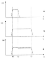
相応の信号特性が図2に例として示されている。図2ではそれぞれ時間Tに関して、aにハイサイドスイッチのスイッチング状態、bにローサイドスイッチのスイッチング状態、cにデータ線路140の状態が示されている。時点T1でデータ伝送が可能となる駆動状態が生じる。この時点からハイサイドスイッチおよびローサイドスイッチの双方が導通状態に置かれる。さらにデータ線路がアクティブとなる。時点T2ではハイサイドスイッチは再び非導通状態に置かれる。これにより時点T1から時点T2までのあいだハイサイドスイッチおよびローサイドスイッチともに閉成状態となり、電流が短時間だけ負荷250を通って流れる。この電流パルスに基づいてデータ担体260はデータ伝送が行われたことを識別する。この識別は有利にはデータ線路がアクティブとなっており、短い持続時間のパルスを有する場合に行われる。
The corresponding signal characteristics are shown by way of example in FIG. In FIG. 2, with respect to time T, a indicates the switching state of the high-side switch, b indicates the switching state of the low-side switch, and c indicates the state of the
データ伝送が報告される状態は、データ線路がアクティブとなっておりかつ所定の駆動状態が生じている負荷の駆動状態とは区別される。共通しているのはハイサイドスイッチおよびローサイドスイッチの駆動状態であって、これらが操作されて導通している点は同じである。このことは他方の状態でも同様である。ハイサイドスイッチおよびローサイドスイッチが操作されることにより、負荷250への通電が行われる。
The state in which data transmission is reported is distinguished from the drive state of the load in which the data line is active and the predetermined drive state occurs. The driving state of the high-side switch and the low-side switch is common, and they are operated to be conductive. This is the same in the other state. When the high-side switch and the low-side switch are operated, the
ハイサイドスイッチが非導通状態となる時点T2からデータ線路140を介してデータ伝送が行われる。これは図2のcに点線で示されている。時点T3でデータ伝送が終了する。このことは制御ユニットからデータ担体へシグナリングされ、ローサイドスイッチは前述の場合と同様に非導通状態へ移行し、データ線路はアクティブでなくなる。
(4) Data transmission is performed via the
有利には個別のデータ線路を備えた手段ではデータ担体のアクチュエータにアース端子が必要なくなる。 Advantageously, means with separate data lines eliminate the need for a ground terminal on the actuator of the data carrier.
本発明の手段をマグネットバルブを備えた負荷の実施例に則して説明した。ここでは負荷のグループごとに単一のハイサイドスイッチを設け、各負荷ごとに1つずつローサイドスイッチを設けている。ただしこれに代えて、ハイサイドスイッチおよびローサイドスイッチの機能を交換してもよい。さらに負荷ごとに単一のスイッチング手段を設ける構成を適用することもできる。 手段 The means of the present invention have been described with reference to the embodiment of the load having the magnet valve. Here, a single high-side switch is provided for each group of loads, and one low-side switch is provided for each load. However, instead of this, the functions of the high side switch and the low side switch may be exchanged. Further, a configuration in which a single switching means is provided for each load can be applied.
また本発明の手段はマグネットバルブを備えたアクチュエータのみに限定されない。本発明はピエゾアクチュエータを備えた1つまたは複数の可動エレメントにも使用可能である。 The means of the present invention is not limited to only an actuator having a magnet valve. The invention can also be used with one or more movable elements with piezo actuators.
100 制御装置
110 制御ユニット
112 量補償制御部
114 ゼロ量補正部
120、125 スイッチング手段
130 ハイサイド線路
135 ローサイド線路
140 データ線路
200 アクチュエータ
250 負荷
260 データ担体
REFERENCE SIGNS
Claims (5)
ここでデータ担体は当該のアクチュエータを表すデータを含む、
内燃機関の制御方法において、
データを制御装置によってデータ担体へ書き込むことができる
ことを特徴とする内燃機関の制御方法。 Reading data from the data carrier assigned to the at least one actuator by the control device and using the data for control;
Wherein the data carrier contains data representing the actuator in question;
In a control method for an internal combustion engine,
A method for controlling an internal combustion engine, wherein data can be written to a data carrier by a control device.
ここでデータ担体は当該のアクチュエータを表すデータを含む、
内燃機関の制御装置において、
データが制御装置によってデータ担体へ書き込まれる
ことを特徴とする内燃機関の制御装置。 Data is read from the data carrier assigned to the at least one actuator by the control device and used for control,
Wherein the data carrier contains data representing the actuator in question;
In the control device of the internal combustion engine,
A control device for an internal combustion engine, characterized in that data is written to a data carrier by the control device.
Applications Claiming Priority (1)
| Application Number | Priority Date | Filing Date | Title |
|---|---|---|---|
| DE2002144091 DE10244091A1 (en) | 2002-09-23 | 2002-09-23 | Method and device for controlling an internal combustion engine |
Publications (1)
| Publication Number | Publication Date |
|---|---|
| JP2004116523A true JP2004116523A (en) | 2004-04-15 |
Family
ID=31896290
Family Applications (1)
| Application Number | Title | Priority Date | Filing Date |
|---|---|---|---|
| JP2003330253A Pending JP2004116523A (en) | 2002-09-23 | 2003-09-22 | Control method and device for internal combustion engine |
Country Status (3)
| Country | Link |
|---|---|
| EP (1) | EP1400674B1 (en) |
| JP (1) | JP2004116523A (en) |
| DE (2) | DE10244091A1 (en) |
Cited By (5)
| Publication number | Priority date | Publication date | Assignee | Title |
|---|---|---|---|---|
| JP2007224915A (en) * | 2006-02-24 | 2007-09-06 | Beru Ag | Internal combustion engine for vehicle, particularly diesel engine |
| US7628146B2 (en) | 2004-11-04 | 2009-12-08 | Robert Bosch Gmbh | Device and method for correcting the injection behavior of an injector |
| CN103180589A (en) * | 2010-11-03 | 2013-06-26 | 罗伯特·博世有限公司 | Method for operating a switching element |
| CN103180588A (en) * | 2010-11-03 | 2013-06-26 | 罗伯特·博世有限公司 | Method for operating a magnetic switching element |
| JP2016211477A (en) * | 2015-05-12 | 2016-12-15 | 株式会社デンソー | Injection control device |
Families Citing this family (10)
| Publication number | Priority date | Publication date | Assignee | Title |
|---|---|---|---|---|
| DE102004050761A1 (en) * | 2004-10-16 | 2006-04-20 | Robert Bosch Gmbh | Method for correcting of injection characteristic of injector for injecting of fuel into cylinder of internal combustion engine entails altering information characterizing injection on basis of cylinder-specific adjusting value |
| DE102005001425A1 (en) * | 2005-01-12 | 2006-07-20 | Robert Bosch Gmbh | Device for controlling an internal combustion engine |
| DE102007018627B4 (en) | 2007-04-19 | 2009-08-06 | Continental Automotive France | Method and device for calibrating actuators for internal combustion engines |
| DE102007019099B4 (en) | 2007-04-23 | 2016-12-15 | Continental Automotive Gmbh | Method and device for calibrating fuel injectors |
| DE102007020061B3 (en) * | 2007-04-27 | 2008-10-16 | Siemens Ag | Method and data carrier for reading out and / or storing injector-specific data for controlling an injection system of an internal combustion engine |
| DE102008024546B3 (en) * | 2008-05-21 | 2010-01-07 | Continental Automotive Gmbh | Method for injector-specific adjustment of the injection time of motor vehicles |
| JP2016008516A (en) * | 2014-06-23 | 2016-01-18 | 日野自動車株式会社 | Common rail fuel injection system |
| GB2554436B (en) * | 2016-09-27 | 2019-04-17 | Delphi Tech Ip Ltd | Method for communicating data between a smart fuel injector and an ECU |
| JP6773016B2 (en) * | 2017-12-26 | 2020-10-21 | 株式会社デンソー | Load drive |
| CN113931760B (en) * | 2021-09-26 | 2023-09-29 | 东风商用车有限公司 | Power-on pulse width correction verification method and system for gas engine nozzle |
Family Cites Families (3)
| Publication number | Priority date | Publication date | Assignee | Title |
|---|---|---|---|---|
| JPH076434B2 (en) * | 1991-10-09 | 1995-01-30 | 株式会社ゼクセル | Electronic fuel injection device |
| JP3487207B2 (en) * | 1999-02-01 | 2004-01-13 | 株式会社デンソー | Fuel injection system |
| DE10215610B4 (en) * | 2001-04-10 | 2018-12-13 | Robert Bosch Gmbh | System and method for correcting the injection behavior of at least one injector |
-
2002
- 2002-09-23 DE DE2002144091 patent/DE10244091A1/en not_active Withdrawn
-
2003
- 2003-07-10 DE DE50301536T patent/DE50301536D1/en not_active Expired - Lifetime
- 2003-07-10 EP EP20030015722 patent/EP1400674B1/en not_active Expired - Lifetime
- 2003-09-22 JP JP2003330253A patent/JP2004116523A/en active Pending
Cited By (10)
| Publication number | Priority date | Publication date | Assignee | Title |
|---|---|---|---|---|
| US7628146B2 (en) | 2004-11-04 | 2009-12-08 | Robert Bosch Gmbh | Device and method for correcting the injection behavior of an injector |
| KR101033062B1 (en) * | 2004-11-04 | 2011-05-06 | 로베르트 보쉬 게엠베하 | Device and method for correction of the injection behaviour of an injector |
| JP2007224915A (en) * | 2006-02-24 | 2007-09-06 | Beru Ag | Internal combustion engine for vehicle, particularly diesel engine |
| JP4709967B2 (en) * | 2006-02-24 | 2011-06-29 | ボルクヴァルナー ベルー ジステームズ ゲゼルシャフト ミット ベシュレンクテル ハフツング | Vehicle internal combustion engines, especially diesel engines |
| CN103180589A (en) * | 2010-11-03 | 2013-06-26 | 罗伯特·博世有限公司 | Method for operating a switching element |
| CN103180588A (en) * | 2010-11-03 | 2013-06-26 | 罗伯特·博世有限公司 | Method for operating a magnetic switching element |
| CN103180588B (en) * | 2010-11-03 | 2016-10-19 | 罗伯特·博世有限公司 | For the method running magnetic switch component |
| US9624884B2 (en) | 2010-11-03 | 2017-04-18 | Robert Bosch Gmbh | Method for operating a magnetic switching element |
| US9766290B2 (en) | 2010-11-03 | 2017-09-19 | Robert Bosch Gmbh | Method for operating a switching element |
| JP2016211477A (en) * | 2015-05-12 | 2016-12-15 | 株式会社デンソー | Injection control device |
Also Published As
| Publication number | Publication date |
|---|---|
| EP1400674A2 (en) | 2004-03-24 |
| EP1400674B1 (en) | 2005-11-02 |
| EP1400674A3 (en) | 2004-04-21 |
| DE50301536D1 (en) | 2005-12-08 |
| DE10244091A1 (en) | 2004-04-01 |
Similar Documents
| Publication | Publication Date | Title |
|---|---|---|
| JP2004116523A (en) | Control method and device for internal combustion engine | |
| US7628146B2 (en) | Device and method for correcting the injection behavior of an injector | |
| US6564771B2 (en) | Fuel injection system for an internal combustion engine | |
| KR100284521B1 (en) | One or more electronic load controllers | |
| KR101567201B1 (en) | Device for correction an injector characteristic | |
| US20060201488A1 (en) | Method for controlling a solenoid valve | |
| JP3955622B2 (en) | Control device for at least one electromagnetic load | |
| US9062624B2 (en) | Fuel injector communication system | |
| JP2004116524A (en) | Control method and device for internal combustion engine | |
| JP2002004926A (en) | Fuel injection device and its operating method | |
| US7830218B2 (en) | Communications device and data transmission method | |
| US6522049B2 (en) | Apparatus and method for detecting a short circuit to the battery voltage when driving piezoelectric elements | |
| JP2007534883A (en) | Operation circuit diagnostic method | |
| US11555464B2 (en) | Injector, and device for detecting the condition of such an injector | |
| JP2002021676A (en) | Device and method for detecting decrease of load during drive of piezoelectric element | |
| JP2005201248A (en) | Operation device for inductive electric actuator | |
| US6380659B2 (en) | Method and device for controlling a controller having a capacitive element | |
| EP1139446B1 (en) | Method and apparatus for controlling system parameters | |
| JP5393458B2 (en) | Apparatus and method for determining a fault in a fuel metering unit of an injection system and a computer program for carrying out the method | |
| US8649960B2 (en) | Method and data storage medium for reading and/or storing injector-specific data for controlling an injection system of an internal combustion engine | |
| JP4173696B2 (en) | LOAD CONTROL METHOD AND CONTROL DEVICE | |
| JP2003301741A (en) | Engine system | |
| US7380449B2 (en) | Method and device for testing a fuel metering system | |
| US20210358669A1 (en) | Method for transferring data from an actuating element to a control unit, corresponding actuating element and corresponding control unit | |
| CN114623010A (en) | Method for transmitting data from an actuator to a control device and associated device |
Legal Events
| Date | Code | Title | Description |
|---|---|---|---|
| A621 | Written request for application examination |
Effective date: 20060921 Free format text: JAPANESE INTERMEDIATE CODE: A621 |
|
| A131 | Notification of reasons for refusal |
Free format text: JAPANESE INTERMEDIATE CODE: A131 Effective date: 20080919 |
|
| A521 | Written amendment |
Effective date: 20081212 Free format text: JAPANESE INTERMEDIATE CODE: A523 |
|
| A02 | Decision of refusal |
Free format text: JAPANESE INTERMEDIATE CODE: A02 Effective date: 20090527 |