JP2004116477A - Cooling system for small boat - Google Patents
Cooling system for small boat Download PDFInfo
- Publication number
- JP2004116477A JP2004116477A JP2002284218A JP2002284218A JP2004116477A JP 2004116477 A JP2004116477 A JP 2004116477A JP 2002284218 A JP2002284218 A JP 2002284218A JP 2002284218 A JP2002284218 A JP 2002284218A JP 2004116477 A JP2004116477 A JP 2004116477A
- Authority
- JP
- Japan
- Prior art keywords
- water
- drain
- cooling
- boat
- pipe
- Prior art date
- Legal status (The legal status is an assumption and is not a legal conclusion. Google has not performed a legal analysis and makes no representation as to the accuracy of the status listed.)
- Pending
Links
Images


Classifications
-
- F—MECHANICAL ENGINEERING; LIGHTING; HEATING; WEAPONS; BLASTING
- F01—MACHINES OR ENGINES IN GENERAL; ENGINE PLANTS IN GENERAL; STEAM ENGINES
- F01P—COOLING OF MACHINES OR ENGINES IN GENERAL; COOLING OF INTERNAL-COMBUSTION ENGINES
- F01P11/00—Component parts, details, or accessories not provided for in, or of interest apart from, groups F01P1/00 - F01P9/00
- F01P11/02—Liquid-coolant filling, overflow, venting, or draining devices
- F01P11/0276—Draining or purging
-
- F—MECHANICAL ENGINEERING; LIGHTING; HEATING; WEAPONS; BLASTING
- F01—MACHINES OR ENGINES IN GENERAL; ENGINE PLANTS IN GENERAL; STEAM ENGINES
- F01P—COOLING OF MACHINES OR ENGINES IN GENERAL; COOLING OF INTERNAL-COMBUSTION ENGINES
- F01P2050/00—Applications
- F01P2050/02—Marine engines
- F01P2050/04—Marine engines using direct cooling
Abstract
Description
【0001】
【発明の属する技術分野】
本発明は、小型艇の冷却システムに関するものである。
【0002】
【従来の技術】
従来、小型艇の冷却システムは、船外の水を船内のエンジン等の発熱体である冷却対象へジェットポンプおよび配管で送って冷却した後、船外へ排水する構成となっている(例えば、特許文献1参照)。
【0003】
【特許文献1】
特開2001−98942号公報(第2頁左欄、図1〜6)
【0004】
【発明が解決しようとする課題】
上述したような従来の冷却システムでは、小型艇を陸上に上げて保管した際に、冷却対象ないし配管の一部に水が残ることがあり、その水が残った部位が、腐食したり、冬季においてはその水が凍結することがあるという課題があった。
【0005】
この発明の目的は、以上のような課題を解決し、水経路内に水が残ることを防止することのできる小型艇の冷却システムを提供することにある。
【0006】
【課題を解決するための手段】
上記目的を達成するために請求項1記載の小型艇の冷却システムは、船外の水を船内の冷却対象へポンプおよび配管で送って冷却した後、船外へ排水する小型艇の冷却システムであって、
前記冷却対象ないし配管において水が残りやすい部位にドレインホースを接続し、このドレインホースの他端に、開閉自在の排水口を設けたことを特徴とする。
請求項2記載の小型艇の冷却システムは、請求項1記載の小型艇の冷却システムにおいて、前記ドレインホースは複数設けられ、その排水口に、当該排水口を開閉する単一のドレインユニットが設けられていることを特徴とする。
【0007】
【作用効果】
請求項1記載の小型艇の冷却システムは、船外の水を船内の冷却対象へポンプおよび配管で送って冷却した後、船外へ排水する小型艇の冷却システムであって、前記冷却対象ないし配管において水が残りやすい部位にドレインホースを接続し、このドレインホースの他端に、開閉自在の排水口を設けてあるので、この小型艇の冷却システムによれば、小型艇を陸上に上げて保管する際、上記排水口を開くことによって、上記冷却対象ないし配管において水が残りやすい部位における水を排水することができる。
したがって、水経路内における腐食や凍結を防止することができる。
請求項2記載の小型艇の冷却システムによれば、請求項1記載の小型艇の冷却システムにおいて、前記ドレインホースは複数設けられ、その排水口に、当該排水口を開閉する単一のドレインユニットが設けられているので、この単一のドレンユニットで複数の排水口を開くことにより、上記冷却対象ないし配管において水が残りやすい複数の部位における水を同時に排水することができる。
したがって、複数箇所の排水に要する手間が著しく軽減される。
【0008】
【発明の実施の形態】
以下、本発明の実施の形態について図面を参照して説明する。
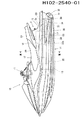
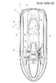
図1は本発明に係る小型艇の冷却システムの一実施の形態を用いた小型滑走艇の一例を示す側面図、図2は同じく平面図である。
【0009】
これらの図(主として図1)に示すように、この小型滑走艇10は、鞍乗り型小型船舶であり、船体11上のシート12に乗員が座り、スロットルレバー付きの操舵ハンドル13を握って操行可能である。
船体11は、ハル14とデッキ15とを接合して内部に空間16を形成した浮体構造となっている。空間16内において、ハル14上には、エンジン20が搭載され、このエンジン20で駆動される推進手段としてのジェットポンプ(ジェット推進ポンプ)30がハル14後部に設けられている。
【0010】
ジェットポンプ30は、船底に開口した取水口17から船体後端に開口した噴流口31およびノズル32に至る流路33と、この流路33内に配置されたインペラ34とを有しており、インペラ34のシャフト35がエンジン20の出力軸20aに連結されている。したがって、エンジン20によりインペラ34が回転駆動されると、取水口17から取り入れられた水が噴流口31からノズル32を経て噴出され、これによって船体11が推進される。エンジン20の駆動回転数、すなわちジェットポンプ30による推進力は、前記操作ハンドル13のスロットルレバー13a(図2参照)の回動操作によって操作される。ノズル32は、図示しない操作ワイヤーで操作ハンドル13と連係されていて、ハンドル13の操作で回動操作され、これによって進路を変更することができる。
【0011】
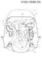
図3は主としてエンジン20を示す図で、図1におけるIII−III部分拡大断面図(部分省略断面図)である。
このエンジン20はDOHC型で直列4気筒のドライサンプ式4サイクルエンジンであり、図1に示すように、そのクランクシャフト20aが船体11の前後方向に沿うように配置されている。
図3に示すように、船体11の進行方向に向かってエンジン20の左側には、吸気ポート20iに連通するサージタンク(インテークチャンバ)21とインタークーラ22とが接続配置され、エンジン20の右側には、排気ポート20oに連通する排気マニホルド23が接続配置されている。
図1に示すように、エンジン20の後方にはターボチャージャ(過給機)24が配置され、このターボチャージャ24のタービン部に排気マニホルド23の排気出口が接続され、ターボチャージャ24のコンプレッサ部に前記インタークーラ22が接続されている。
【0012】
ターボチャージャ24のタービン部にてタービンを回転させた排気は、図1に示すように、第1排気管51,転覆時の水の逆流(ターボチャージャ24等への水の侵入)を防止するための逆流防止室52,および第2排気管53を通じてウォーターマフラ60へと排出され、さらにウォーターマフラ60から排気・排水管54を経てジェットポンプ30による水流内へと排出される。
【0013】
図4は冷却水システムを示す図で、このシステムにおける冷却水の経路を示す図である。
同図に示すように、ジェットポンプ30におけるインペラ34の下流側には冷却水取り入れ口36が設けられており、インペラ34によるジェット水流Wの一部W1が取り入れ口34から取り入れられて冷却水W1として利用される。冷却水W1は取り入れ口34に接続された冷却水パイプP1〜を通じて冷却対象(エンジン20、インタークーラ22等)のウォータジャケットに供給される。
【0014】
この実施の形態では、取り入れ口34に接続された冷却水パイプP1からの冷却水W1は、パイプP2,P3に分岐されている。
一方のパイプP2の冷却水W2は、エンジン20前部に設けられているオイルタンクOT内に収納されたオイルクーラOCに供給されてこれを冷却した後、パイプP4でエンジン20のシリンダブロックおよびシリンダヘッドに供給されてこれらを冷却し、その後、パイプP5を経て船外へ排水される。
他方のパイプP3の冷却水W3は、インタークーラ22に供給されてこれを冷却した後、パイプP6で排気マニホルド23に供給されてこれを冷却する。
【0015】
排気マニホルド23を冷却した冷却水W3は、排気マニホルド23の上部でパイプP7とP8に分岐される。
一方のパイプP7はその先端が図示しないパイロットウォーターノズルに接続されており、パイプP7へ流れた冷却水W4はそのパイロットウォーターノズルから船外へ排水される。
他方のパイプP8へ流れた冷却水W5はターボチャージャ24に供給されてこれを冷却した後、パイプP9で第1排気管51、逆流防止室52、および第2排気管53へと供給され、これらを冷却した後、第2排気管53の下端からウォーターマフラ60内へと噴出されてウォーターマフラ60を冷却するとともに、ウォーターマフラ60内で排気ガスと一緒になり、排気・排水管54を経てジェットポンプ30による水流内(船外)へと排出される。
なお、第1排気管51を冷却した冷却水W5の一部W5’はパイプP10で上記パイプP7へと合流し、冷却水W4とともにパイロットウォーターノズルから船外へ排水される。
【0016】
例えば以上のような冷却システムを用いた小型艇を陸上に上げて保管する際には、冷却対象(エンジン20等)ないし配管Pの一部に水が残ることがある。また、小型艇を海上で利用した場合には、冷却対象および配管Pの内部に真水を供給して海水を洗い流す必要がある。例えば、前記パイプP5から水道水を逆流させて冷却対象および配管Pの内部を洗う必要があるが、このような場合にもやはり、冷却対象ないし配管Pの一部に水が残ることがある。
そして、この残った水を放置すると、水の残った部位が、腐食したり、冬季においてはその水が凍結してしまうことがある。
【0017】
そこで、この実施の形態では、図4に一点鎖線で示すように、冷却対象ないし配管において水が残りやすい部位にドレインホースDH1,DH2,DH3を接続し、このドレインホースDH1,DH2,DH3の他端(DH1a,DH2a,DH3a)に、開閉自在の排水口DH1a,DH2a,DH3aを設けてある。
この実施の形態では、ドレインホースDH1をターボチャージャ24のウォータジャケット下部に、ドレインホースDH2を排気マニホルド23のウォータジャケット下部に、ドレインホースDH3をオイルクーラOCへの冷却水導入パイプP2に、接続してある。
そして、この実施の形態では、上記排水口DH1a,DH2a,DH3aに、当該排水口を開閉する単一のドレインユニットDUを設けてある。
【0018】
図5はドレンユニットDUの拡大図である。図6はドレンユニットDUの本体を示す図で(a)は平面図、(b)は正面図、(c)は左側面図である。図7はドレンユニットDUのプラグを示す図で、(a)は平面図、(b)は部分切断正面図である。
これらの図に示すように、ドレンユニットDUは本体70と、これに抜き差しされるプラグ80とで構成されている。
【0019】
図5および図6に示すように、本体70は、テーパがついた筒状部70aと、この筒状部70aに連通する3本の接続管71,72,73とを有している。筒状部70aと3本の接続管71,72,73とは、連通口71a,72a,73aでそれぞれ連通している。接続管71,72,73には、それぞれ前述したドレインホースDH1,DH2,DH3が接続され、結果として上記連通口71a,72a,73aが、開閉自在の排水口DH1a,DH2a,DH3aを構成している。
筒状部70aの上部には、プラグ80の受け入れ口(嵌合部)70bが設けられている。また、本体70には、これを船体11の適所に取り付けるための取付部74が設けられている。
【0020】
図5および図7に示すように、プラグ80は、キャップ部81と、このキャップ部81の下方に一体に設けられたプラグ部82とを有している。キャップ部81は、摘み部81aと、上記本体70の嵌合部70bと嵌合する嵌合部81bとを有している。プラグ部82には、3本のリング状のシールリップ部83,84,85と、先端シール部86とが設けられている。
【0021】
図5に示すように、プラグ80を本体70にきつく挿入して装着すると、キャップ部81の嵌合部81bが本体70の嵌合部70bと強く密着するとともに、プラグ部82の先端シール部86が本体70の下部内面と強く密着して本体70全体が閉塞された状態となる。したがって、前述したドレインホースDH1,DH2,DH3の排水口DH1a,DH2a,DH3aも閉じられることとなるが、さらに、排水口DH1aはシールリップ部83と84とで隔絶され、排水口DH2aはシールリップ部84と85とで隔絶され、排水口DH3aはシールリップ部85と先端シール部86とで隔絶され、結果として、これら排水口DH1a,DH2a,DH3a、および本体70が良好に閉塞された状態となる。
したがって、本体70にプラグ80が装着された状態では、上述した冷却システムにおける流水状態は良好に維持される。
【0022】
一方、小型艇を陸上に上げて保管する際には、必要に応じ(海上等で使用した場合等)、冷却対象および配管Pの内部に真水を供給して海水を洗い流した後に、本体70からプラグ80を抜く。
これによって、上記排水口DH1a,DH2a,DH3aが開口し、冷却対象ないし配管Pの一部に残ろうとする水が、ドレインホースDH1,DH2,DH3および、本体70を経て上記冷却システム外へ排出されることとなる。
【0023】
以上説明したように、この小型艇の冷却システムは、船外の水を船内の冷却対象へジェットポンプ30および配管P1等で送って冷却した後、船外へ排水する小型艇の冷却システムであり、冷却対象ないし配管において水が残りやすい部位にドレインホースDH1等を接続し、このドレインホースDH1等の他端に、開閉自在の排水口DH1a等を設けてあるので、この小型艇の冷却システムによれば、小型艇10を陸上に上げて保管する際、上記排水口DH1a等を開くことによって、上記冷却対象ないし配管において水が残りやすい部位における水を排水することができる。
したがって、水経路内における腐食や凍結を防止することができる。
また、ドレインホースは複数設けられ、その排水口DH1a,DH2a,DH3aに、当該排水口DH1a,DH2a,DH3aを開閉する単一のドレインユニットDUが設けられているので、この単一のドレンユニットDUで複数の排水口DH1a,DH2a,DH3aを開くことにより、上記冷却対象ないし配管において水が残りやすい複数の部位における水を同時に排水することができる。
したがって、複数箇所の排水に要する手間が著しく軽減される。
【0024】
以上、本発明の実施の形態について説明したが、本発明は上記の実施の形態に限定されるものではなく、本発明の要旨の範囲内において適宜変形実施可能である。
例えば、上記実施の形態では、ドレインホースDH1をターボチャージャ24のウォータジャケット下部に、ドレインホースDH2を排気マニホルド23のウォータジャケット下部に、ドレインホースDH3をオイルクーラOCへの冷却水導入パイプP2に接続したが、ドレインホースの本数およびその接続箇所は適宜設定することができる。
【0025】
【図面の簡単な説明】
【図1】本発明に係る小型艇の冷却システムの一実施の形態を用いた小型滑走艇の一例を示す側面図。
【図2】同じく平面図。
【図3】主としてエンジン20を示す図で、図1におけるIII−III部分拡大断面図(部分省略断面図)。
【図4】冷却水システムを示す図で、冷却水の経路を示す図。
【図5】ドレンユニットDUの拡大図。
【図6】ドレンユニットDUの本体を示す図で(a)は平面図、(b)は正面図、(c)は左側面図。
【図7】ドレンユニットDUのプラグを示す図で、(a)は平面図、(b)は部分切断正面図。
【符号の説明】
10 小型艇
20 エンジン(冷却対象)
22 インタークーラ(冷却対象)
23 排気マニホルド(冷却対象)
24 ターボチャージャ(冷却対象)
30 ジェットポンプ(ポンプ)
51 第1排気管(冷却対象)
P1〜P10 配管
DH1〜DH3 ドレインホース
DH1a〜DH3a 排水口
DU ドレインユニット[0001]
TECHNICAL FIELD OF THE INVENTION
The present invention relates to a cooling system for a small boat.
[0002]
[Prior art]
Conventionally, a cooling system for a small boat has a configuration in which outboard water is sent to a cooling target, which is a heating element such as an engine in a ship, by a jet pump and piping, cooled, and then drained outboard (for example, Patent Document 1).
[0003]
[Patent Document 1]
JP 2001-98942 A (left column of page 2, FIGS. 1 to 6)
[0004]
[Problems to be solved by the invention]
In the conventional cooling system as described above, when a small boat is raised and stored on land, water may remain on the part to be cooled or on part of the piping, and the remaining water may be corroded or damaged in winter. Has a problem that the water may freeze.
[0005]
An object of the present invention is to solve the above-described problems and to provide a cooling system for a small boat that can prevent water from remaining in a water path.
[0006]
[Means for Solving the Problems]
In order to achieve the above object, a cooling system for a small boat according to claim 1 is a cooling system for a small boat, which pumps outboard water to a cooling object in the boat by a pump and pipes, cools the water, and then discharges the water outside the boat. So,
A drain hose is connected to a portion of the cooling target or the pipe where water easily remains, and a drain port that can be opened and closed is provided at the other end of the drain hose.
The cooling system for a small boat according to claim 2 is the cooling system for a small boat according to claim 1, wherein a plurality of the drain hoses are provided, and a single drain unit for opening and closing the drain port is provided at a drain port thereof. It is characterized by having been done.
[0007]
[Effects]
The cooling system for a small boat according to claim 1, wherein the cooling system for the small boat is configured to send outboard water to a cooling object in the boat by a pump and a pipe, cool the water, and then discharge the water to the outside of the boat. A drain hose is connected to a portion of the pipe where water easily remains, and a drain port that can be opened and closed is provided at the other end of the drain hose. During storage, by opening the drain port, it is possible to drain the water in the cooling target or the pipe where water tends to remain.
Therefore, corrosion and freezing in the water path can be prevented.
According to the cooling system for a small boat according to claim 2, in the cooling system for a small boat according to claim 1, a plurality of the drain hoses are provided, and a single drain unit that opens and closes the drain port is provided at a drain port thereof. Is provided, by opening a plurality of drain ports with this single drain unit, it is possible to simultaneously drain water at a plurality of locations where water is likely to remain in the cooling target or the piping.
Therefore, the labor required for draining at a plurality of locations is significantly reduced.
[0008]
BEST MODE FOR CARRYING OUT THE INVENTION
Hereinafter, embodiments of the present invention will be described with reference to the drawings.
FIG. 1 is a side view showing an example of a personal watercraft using an embodiment of a small boat cooling system according to the present invention, and FIG. 2 is a plan view of the same.
[0009]
As shown in these drawings (mainly in FIG. 1), this
The
[0010]
The
[0011]
FIG. 3 is a view mainly showing the
This
As shown in FIG. 3, a surge tank (intake chamber) 21 communicating with an intake port 20 i and an
As shown in FIG. 1, a turbocharger (supercharger) 24 is disposed behind the
[0012]
As shown in FIG. 1, the exhaust gas whose turbine has been rotated by the turbine unit of the
[0013]
FIG. 4 is a diagram showing a cooling water system, and is a diagram showing a route of cooling water in this system.
As shown in the figure, a
[0014]
In this embodiment, the cooling water W1 from the cooling water pipe P1 connected to the
The cooling water W2 of one pipe P2 is supplied to an oil cooler OC stored in an oil tank OT provided at the front of the
The cooling water W3 of the other pipe P3 is supplied to the
[0015]
The cooling water W3 that has cooled the
One end of the pipe P7 is connected to a pilot water nozzle (not shown), and the cooling water W4 flowing to the pipe P7 is drained out of the boat from the pilot water nozzle.
The cooling water W5 flowing to the other pipe P8 is supplied to the
A part W5 ′ of the cooling water W5 that has cooled the
[0016]
For example, when a small boat using the above-described cooling system is lifted and stored on land, water may remain on a cooling object (the
If the remaining water is left untreated, the remaining water may be corroded, or the water may freeze in winter.
[0017]
Therefore, in this embodiment, as shown by a dashed line in FIG. 4, drain hoses DH1, DH2, and DH3 are connected to a portion where water is likely to remain in a cooling object or a pipe, and the drain hoses DH1, DH2, and DH3 are connected. At the ends (DH1a, DH2a, DH3a), openable / closable drain ports DH1a, DH2a, DH3a are provided.
In this embodiment, the drain hose DH1 is connected to the lower part of the water jacket of the
In this embodiment, a single drain unit DU that opens and closes the drain port is provided in the drain ports DH1a, DH2a, and DH3a.
[0018]
FIG. 5 is an enlarged view of the drain unit DU. 6A and 6B are views showing the main body of the drain unit DU, wherein FIG. 6A is a plan view, FIG. 6B is a front view, and FIG. 6C is a left side view. FIGS. 7A and 7B are views showing a plug of the drain unit DU, wherein FIG. 7A is a plan view and FIG.
As shown in these figures, the drain unit DU is composed of a
[0019]
As shown in FIGS. 5 and 6, the
A receiving port (fitting portion) 70b for the
[0020]
As shown in FIGS. 5 and 7, the
[0021]
As shown in FIG. 5, when the
Therefore, when the
[0022]
On the other hand, when the small boat is raised on land and stored, if necessary (such as when used at sea or the like), the fresh water is supplied to the object to be cooled and the inside of the pipe P to wash out the seawater, and then the
As a result, the drain ports DH1a, DH2a, and DH3a are opened, and water that is going to remain in a part to be cooled or a part of the pipe P is discharged out of the cooling system through the drain hoses DH1, DH2, DH3, and the
[0023]
As described above, this cooling system for a small boat is a cooling system for a small boat that sends outboard water to a cooling object in the boat by a
Therefore, corrosion and freezing in the water path can be prevented.
Further, a plurality of drain hoses are provided, and a single drain unit DU for opening and closing the drain ports DH1a, DH2a, DH3a is provided at the drain ports DH1a, DH2a, DH3a. By opening a plurality of drain ports DH1a, DH2a, and DH3a, water at a plurality of locations where water is likely to remain in the cooling target or the piping can be drained at the same time.
Therefore, the labor required for draining at a plurality of locations is significantly reduced.
[0024]
Although the embodiments of the present invention have been described above, the present invention is not limited to the above embodiments, and can be appropriately modified and implemented within the scope of the present invention.
For example, in the above embodiment, the drain hose DH1 is connected to the lower part of the water jacket of the
[0025]
[Brief description of the drawings]
FIG. 1 is a side view showing an example of a personal watercraft using an embodiment of a small boat cooling system according to the present invention.
FIG. 2 is a plan view of the same.
3 is a view mainly showing an
FIG. 4 is a view showing a cooling water system and showing a path of cooling water.
FIG. 5 is an enlarged view of a drain unit DU.
6A and 6B are diagrams showing a main body of the drain unit DU, wherein FIG. 6A is a plan view, FIG. 6B is a front view, and FIG. 6C is a left side view.
FIGS. 7A and 7B are views showing a plug of the drain unit DU, wherein FIG. 7A is a plan view and FIG.
[Explanation of symbols]
10
22 Intercooler (to be cooled)
23 Exhaust manifold (to be cooled)
24 Turbocharger (to be cooled)
30 jet pump (pump)
51 1st exhaust pipe (to be cooled)
P1 to P10 Piping DH1 to DH3 Drain hose DH1a to DH3a Drain outlet DU Drain unit
Claims (2)
前記冷却対象ないし配管において水が残りやすい部位にドレインホースを接続し、このドレインホースの他端に、開閉自在の排水口を設けたことを特徴とする小型艇の冷却システム。A cooling system for a small boat, which pumps outboard water to a cooling target inside the boat using a pump and piping to cool the water, and then discharges the water outside the boat,
A cooling system for a small boat, wherein a drain hose is connected to a portion of the cooling object or the pipe where water tends to remain, and a drain port that can be opened and closed is provided at the other end of the drain hose.
Priority Applications (3)
| Application Number | Priority Date | Filing Date | Title |
|---|---|---|---|
| JP2002284218A JP2004116477A (en) | 2002-09-27 | 2002-09-27 | Cooling system for small boat |
| CA002442425A CA2442425C (en) | 2002-09-27 | 2003-09-24 | Cooling system for a small vessel |
| US10/672,934 US6875070B2 (en) | 2002-09-27 | 2003-09-26 | Cooling system for a small watercraft |
Applications Claiming Priority (1)
| Application Number | Priority Date | Filing Date | Title |
|---|---|---|---|
| JP2002284218A JP2004116477A (en) | 2002-09-27 | 2002-09-27 | Cooling system for small boat |
Publications (1)
| Publication Number | Publication Date |
|---|---|
| JP2004116477A true JP2004116477A (en) | 2004-04-15 |
Family
ID=32211527
Family Applications (1)
| Application Number | Title | Priority Date | Filing Date |
|---|---|---|---|
| JP2002284218A Pending JP2004116477A (en) | 2002-09-27 | 2002-09-27 | Cooling system for small boat |
Country Status (3)
| Country | Link |
|---|---|
| US (1) | US6875070B2 (en) |
| JP (1) | JP2004116477A (en) |
| CA (1) | CA2442425C (en) |
Cited By (1)
| Publication number | Priority date | Publication date | Assignee | Title |
|---|---|---|---|---|
| JP2006177217A (en) * | 2004-12-21 | 2006-07-06 | Mitsubishi Agricult Mach Co Ltd | Engine cooling device |
Families Citing this family (9)
| Publication number | Priority date | Publication date | Assignee | Title |
|---|---|---|---|---|
| US7168998B1 (en) | 2004-08-03 | 2007-01-30 | Accessible Technologies, Inc. | Personal watercraft forced air induction system |
| JP4620633B2 (en) * | 2006-05-19 | 2011-01-26 | 本田技研工業株式会社 | Small planing boat internal combustion engine |
| US7585196B1 (en) | 2006-06-01 | 2009-09-08 | Brunswick Corporation | Marine propulsion system with an open cooling system that automatically drains when the marine vessel is taken out of the water |
| US7329162B1 (en) * | 2006-06-01 | 2008-02-12 | Brunswick Corporation | Cooling system for a marine propulsion device |
| US9545985B1 (en) * | 2016-06-21 | 2017-01-17 | Brian Provost | Outboard-motor closed-loop cooler system method |
| US10670157B2 (en) * | 2017-05-24 | 2020-06-02 | Rudolph Eberstadt, III | Marine drain valve |
| US10059406B1 (en) * | 2017-05-24 | 2018-08-28 | Rudolph Eberstadt, III | Marine drain valve |
| CN109723531A (en) * | 2019-03-01 | 2019-05-07 | 厦门厦杏摩托有限公司 | A kind of motorcycle engine piston cooling oil path system |
| WO2020227187A1 (en) * | 2019-05-08 | 2020-11-12 | Eberstadt Rudolph Iii | Marine drain valve |
Family Cites Families (3)
| Publication number | Priority date | Publication date | Assignee | Title |
|---|---|---|---|---|
| US4932348A (en) * | 1989-05-08 | 1990-06-12 | Nix Charles D | Remote control valve |
| US5628285A (en) * | 1995-08-31 | 1997-05-13 | Brunswick Corporation | Drain valve for a marine engine |
| JP4469037B2 (en) | 1999-09-30 | 2010-05-26 | ヤマハ発動機株式会社 | Small ship cooling system |
-
2002
- 2002-09-27 JP JP2002284218A patent/JP2004116477A/en active Pending
-
2003
- 2003-09-24 CA CA002442425A patent/CA2442425C/en not_active Expired - Fee Related
- 2003-09-26 US US10/672,934 patent/US6875070B2/en not_active Expired - Fee Related
Cited By (2)
| Publication number | Priority date | Publication date | Assignee | Title |
|---|---|---|---|---|
| JP2006177217A (en) * | 2004-12-21 | 2006-07-06 | Mitsubishi Agricult Mach Co Ltd | Engine cooling device |
| JP4537193B2 (en) * | 2004-12-21 | 2010-09-01 | 三菱農機株式会社 | Engine cooling system |
Also Published As
| Publication number | Publication date |
|---|---|
| CA2442425C (en) | 2007-01-02 |
| US6875070B2 (en) | 2005-04-05 |
| US20040106338A1 (en) | 2004-06-03 |
| CA2442425A1 (en) | 2004-03-27 |
Similar Documents
| Publication | Publication Date | Title |
|---|---|---|
| JP3487885B2 (en) | Muffler cooling structure for watercraft engine | |
| JP2004116477A (en) | Cooling system for small boat | |
| JP2003027947A (en) | Small-sized planing boat equipped with internal combustion engine with supercharger | |
| JP3983153B2 (en) | Small boat intake structure | |
| JPH11291989A (en) | Lubricating oil cooling device for internal combustion engine for ship | |
| JP4688836B2 (en) | Small boat exhaust system | |
| US6612883B2 (en) | Output shaft structure of personal watercraft | |
| JP2003027948A (en) | Heat exchanger | |
| JP4197128B2 (en) | Small boat exhaust system | |
| JP3821671B2 (en) | Sensor arrangement structure for small planing boat engine | |
| US7326093B2 (en) | Personal watercraft | |
| JP3818905B2 (en) | Ship exhaust and drainage structure | |
| JP2003049645A (en) | Water jet propulsion boat | |
| JP4275489B2 (en) | Exhaust resonator drainage structure | |
| JP2003011890A (en) | Small-sized planing boat | |
| JP2003074445A (en) | Engine output control device for water jet propulsion boat | |
| JP3384918B2 (en) | Cooling structure of engine for small watercraft | |
| CA2390395C (en) | Sensor arrangement structure for personal watercraft | |
| JP3904414B2 (en) | Ignition system for small planing boat engine | |
| US6843692B2 (en) | Personal watercraft | |
| JP4253208B2 (en) | Small planing boat | |
| JP2003040196A (en) | Jet propulsion planing boat | |
| JP2004114947A (en) | Pipe or cable supporting structure of small boat | |
| JP4519881B2 (en) | Small boat intake structure | |
| JP2001146196A (en) | Riding type small watercraft |
Legal Events
| Date | Code | Title | Description |
|---|---|---|---|
| A621 | Written request for application examination |
Free format text: JAPANESE INTERMEDIATE CODE: A621 Effective date: 20041202 |
|
| A977 | Report on retrieval |
Free format text: JAPANESE INTERMEDIATE CODE: A971007 Effective date: 20070314 |
|
| A131 | Notification of reasons for refusal |
Free format text: JAPANESE INTERMEDIATE CODE: A131 Effective date: 20070320 |
|
| A521 | Written amendment |
Free format text: JAPANESE INTERMEDIATE CODE: A523 Effective date: 20070518 |
|
| A02 | Decision of refusal |
Free format text: JAPANESE INTERMEDIATE CODE: A02 Effective date: 20070619 |