JP2004114688A - Inkjet printer system and inkjet printing method - Google Patents
Inkjet printer system and inkjet printing method Download PDFInfo
- Publication number
- JP2004114688A JP2004114688A JP2003331860A JP2003331860A JP2004114688A JP 2004114688 A JP2004114688 A JP 2004114688A JP 2003331860 A JP2003331860 A JP 2003331860A JP 2003331860 A JP2003331860 A JP 2003331860A JP 2004114688 A JP2004114688 A JP 2004114688A
- Authority
- JP
- Japan
- Prior art keywords
- receiving layer
- medium
- droplets
- ink
- dot size
- Prior art date
- Legal status (The legal status is an assumption and is not a legal conclusion. Google has not performed a legal analysis and makes no representation as to the accuracy of the status listed.)
- Pending
Links
Images


Classifications
-
- B—PERFORMING OPERATIONS; TRANSPORTING
- B41—PRINTING; LINING MACHINES; TYPEWRITERS; STAMPS
- B41M—PRINTING, DUPLICATING, MARKING, OR COPYING PROCESSES; COLOUR PRINTING
- B41M5/00—Duplicating or marking methods; Sheet materials for use therein
-
- B—PERFORMING OPERATIONS; TRANSPORTING
- B41—PRINTING; LINING MACHINES; TYPEWRITERS; STAMPS
- B41J—TYPEWRITERS; SELECTIVE PRINTING MECHANISMS, i.e. MECHANISMS PRINTING OTHERWISE THAN FROM A FORME; CORRECTION OF TYPOGRAPHICAL ERRORS
- B41J11/00—Devices or arrangements of selective printing mechanisms, e.g. ink-jet printers or thermal printers, for supporting or handling copy material in sheet or web form
- B41J11/009—Detecting type of paper, e.g. by automatic reading of a code that is printed on a paper package or on a paper roll or by sensing the grade of translucency of the paper
-
- B—PERFORMING OPERATIONS; TRANSPORTING
- B41—PRINTING; LINING MACHINES; TYPEWRITERS; STAMPS
- B41J—TYPEWRITERS; SELECTIVE PRINTING MECHANISMS, i.e. MECHANISMS PRINTING OTHERWISE THAN FROM A FORME; CORRECTION OF TYPOGRAPHICAL ERRORS
- B41J13/00—Devices or arrangements of selective printing mechanisms, e.g. ink-jet printers or thermal printers, specially adapted for supporting or handling copy material in short lengths, e.g. sheets
- B41J13/0081—Sheet-storing packages, e.g. for protecting the sheets against ambient influences, e.g. light, humidity, changes in temperature
-
- B—PERFORMING OPERATIONS; TRANSPORTING
- B41—PRINTING; LINING MACHINES; TYPEWRITERS; STAMPS
- B41J—TYPEWRITERS; SELECTIVE PRINTING MECHANISMS, i.e. MECHANISMS PRINTING OTHERWISE THAN FROM A FORME; CORRECTION OF TYPOGRAPHICAL ERRORS
- B41J2/00—Typewriters or selective printing mechanisms characterised by the printing or marking process for which they are designed
- B41J2/005—Typewriters or selective printing mechanisms characterised by the printing or marking process for which they are designed characterised by bringing liquid or particles selectively into contact with a printing material
- B41J2/01—Ink jet
- B41J2/21—Ink jet for multi-colour printing
- B41J2/2121—Ink jet for multi-colour printing characterised by dot size, e.g. combinations of printed dots of different diameter
Abstract
Description
本発明は、インクジェット印刷システム及び印刷方法、及びそれとともに用いるための受容層(又は受容部材)に関する。 The present invention relates to an inkjet printing system and a printing method, and a receiving layer (or a receiving member) to be used therewith.
インクジェット印刷は、例えば、その非衝撃性、低騒音特性及びシステムの単純さに起因して、ディジタル制御式の電子印刷の業界では競争力のある卓越した存在として認識されるようになってきている。これらの理由により、インクジェットプリンタは、家庭用、業務用及び他の分野において商業的成功を収めている。インクジェット印刷の機構は、連続式(CIJ)又はドロップ・オン・デマンド式(DOD)のいずれかに分類可能である。 Ink-jet printing has come to be recognized as a competitive advantage in the digitally controlled electronic printing industry, for example, due to its non-impact, low-noise properties and simplicity of the system. . For these reasons, inkjet printers have achieved commercial success in the home, commercial and other fields. Ink jet printing mechanisms can be classified as either continuous (CIJ) or drop-on-demand (DOD).
1970年にカイザー(Kyser)ほかに発行された特許文献1は、高い電圧を圧電結晶に印加することで当該圧電結晶を曲げさせ、インク貯蔵器に圧力をかけてオンデマンドでインク滴を噴射するDODインクジェットプリンタを開示している。圧電式DODプリンタは、家庭用及び業務用プリンタとして、720dpi(ドット毎インチ)を超える画像解像度で商業的成功を収めている。 U.S. Pat. No. 6,037,028 issued to Kyser et al. In 1970, applies a high voltage to a piezoelectric crystal to bend the piezoelectric crystal and apply pressure to an ink reservoir to eject ink droplets on demand. A DOD inkjet printer is disclosed. Piezoelectric DOD printers have achieved commercial success as image printers for home and business use with image resolutions exceeding 720 dpi (dots per inch).
1979年に遠藤ほかに発行された特許文献2は、インク液路(インクチャンネル)中の水性インクと熱的に接触しているヒータに電力パルスを印加する電熱式ドロップ・オン・デマンド・インクジェットプリンタを開示している。少量のインクは即座に蒸発して気泡を形成し、これによりインク滴がインク液路の端部に沿った複数の小さな開口部から射出される。この技術は、サーマルインクジェット又はバブルジェット(登録商標)として知られている。サーマルインクジェット印刷は、典型的には、急速に気泡を発生させる400℃近い温度にまでインクを加熱するのに十分なエネルギー衝撃をヒータが生成することを必要とする。 Patent Document 2, issued to Endo et al. In 1979, discloses an electrothermal drop-on-demand inkjet printer that applies a power pulse to a heater that is in thermal contact with aqueous ink in an ink channel (ink channel). Is disclosed. The small amount of ink quickly evaporates to form air bubbles, which cause ink droplets to be ejected from a plurality of small openings along the end of the ink passage. This technique is known as thermal ink jet or bubble jet. Thermal inkjet printing typically requires that the heater generate enough energy bombardment to heat the ink to a temperature close to 400 ° C., which causes rapid bubbling.
1982年8月24日にカール・エイチ・ヘルツ(Carl H. Hertz)名義で発行された「小液滴上の電荷を制御するための方法及び装置と、これを組み込んだインクジェット記録装置(METHOD AND APPARATUS FOR CONTROLLING THE ELECTRIC CHARGE ON DROPLETS AND INK JET RECORDER INCORPORATING THE SAME)」と題する特許文献3は、CIJシステムを開示している。このようなシステムでは、生成される小液滴は荷電され、次に排水溝(ガター)の中にかもしくは印刷媒体上に向かって偏向される必要がある。 "A method and apparatus for controlling the charge on small droplets, and an inkjet recording apparatus (METHOD AND) incorporating the same, published on August 24, 1982 under the name of Carl H. Hertz. Patent Document 3 entitled "APPARATUS FOR CONTROLLING THE ELECTRIC CHARGE ON DROPLETS AND INK JET RECORDER INCORPORATING THE SAME" discloses a CIJ system. In such a system, the generated droplets need to be charged and then deflected into a gutter or onto the print media.
1998年4月14日に中村治夫に発行された「離隔配置された電極間の静電気的な引力により変形された弾性プレートを有する電界駆動型インクジェットプリンタ(ELECTRIC FIELD DRIVEN INK JET PRINTER HAVING A RESILIENT PLATE DEFORMED BY AN ELECTROSTATIC ATTRACTION FORCE BETWEEN SPACED APART ELECTRODES)」と題する特許文献4は、透明なガラス基板を介して外部からのレーザ光を照射する電界駆動型の印刷ヘッドを開示している。レーザ光が光伝導材料に当たると、これは導電性になり、こうして電界に対する電気的な経路が完成する。電気的な経路が完成すると、電界は個別のセグメントの周りで消滅する。これらのセグメントは、印加される電界に対するそれらの電気機械的な応答に起因して変形された状態にある。ひとまとまりのインクに接触している個別のセグメントは弛緩し、それによって、一定の容積のインクをノズルプレートから噴出させる。 Published by Haruo Nakamura on April 14, 1998, "ELECTRIC FIELD DRIVEN INK JET PRINTER HAVING A RESILIENT PLATE DEFORMED Patent Document 4 entitled "BY AN ELECTROSTATIC ATTRACTION FORCE BETWEEN SPACED APART ELECTRODES" discloses an electric field driven print head that irradiates an external laser beam through a transparent glass substrate. When the laser light hits the photoconductive material, it becomes conductive, thus completing the electrical path to the electric field. When the electrical path is completed, the electric field disappears around the individual segments. These segments are in a deformed state due to their electromechanical response to an applied electric field. The individual segments in contact with the batch of ink relax, thereby causing a volume of ink to be ejected from the nozzle plate.
これに対して、1999年3月19日にキーア・シルヴァーブルック(Kia Silverbrook)名義で発行された「液体インク印刷装置及びシステム(LIQUID INK PRINTING APPARATUS AND SYSTEM)」と題する特許文献5と、ジェームズ・クワレク(James Chwalek)ほかの名義で発行された「非対称加熱の液滴の偏向による連続式インクジェットプリンタ(CONTINUOUS INK JET PRINTER WITH ASYMMETRIC HEATING DROP DEFLECTION)」と題する特許文献6と、アナグノストプロス(Anagnostopoulos)ほかの名義で公開された特許文献7とは、経済的に有利に製造可能な、ページ幅の高解像度インクジェット印刷により良く適合する伸長された長さの印刷ヘッドを提供するように改良された液体印刷システムを開示している。本願明細書で使用されているように、「ページ幅」という用語は、最短長さが約4インチ(10.2cm)である印刷ヘッドを示す。高解像度は、各インクの色について、1インチ当たり最小で約150個のノズルから最大で約6000個のノズルまでのノズル密度を指す。 In contrast, Patent Literature 5 entitled "LIQUID INK PRINTING APPARATUS AND SYSTEM" issued on March 19, 1999 under the name of Kia Silverbrook, and James Patents 6, entitled "CONTINUOUS INK JET PRINTER WITH ASYMMETRIC HEATING DROP DEFLECTION", issued under the name of James Chwalek et al., And Anagnostopoulos. US Pat. No. 5,049,045, issued under another name, discloses a liquid that has been improved to provide an extended length printhead that is more economically manufacturable and more well suited to high resolution inkjet printing of page width. A printing system is disclosed. As used herein, the term "page width" refers to a printhead having a minimum length of about 4 inches (10.2 cm). High resolution refers to a nozzle density from a minimum of about 150 nozzles per inch to a maximum of about 6000 nozzles per inch for each ink color.
インクジェット印刷において最も画像を損なう欠陥のうちの1つは、複数の湿ったインク滴が受容層表面で互いに接触する際に観察される凝集又はパドリング(濁り)である。高速印刷において発生する場合の多いこの凝集性のアーティファクトにより、画像はしみの多いもの、又は「濁った」ものとなって表れ、結果的に、塗りつぶすように印刷された領域における不均一さをもたらす。パルマーほかによって非特許文献1の刊行物において述べられているように、オーバーヘッド転写フィルムには、隣接するドット間の最適なオーバーラップが達成されるまでに3.5倍の係数でインク滴の拡散が許容されることで、画像が記録されていてもよい。受容層表面における複数のインク滴間の接触を防止するためには、衝突直後のインク滴の最大の直径が画素の間隔より小さくなければならない。次いで、ドットサイズは、インク滴が表面に浸透した後に大幅に増大し、最適なドットサイズに到達する。さらに、モリス(Morris)ほかの特許文献8では、ドットは1/R未満のサイズでありかつドットは約2.0/Rまで増大できるように、インクドットが受容層媒体に印刷される印刷方法が説明されている。しかしながら、モリスらによって提示された例では、印刷後の画像現像(image development)は、溶媒の除去による、特に取外し可能な保護シートの間に画像媒体を配置することによる、半径方向の拡散を停止する形式で提供される必要がある。さらにモリスらは、彼らの例のすべてにおいて2パス印刷に言及し、従って、インク滴の凝集なしに高速のシングルパス印刷が実現されうるということは認識していない。
One of the most image impairing defects in ink jet printing is the agglomeration or paddling observed when multiple wet ink drops contact each other on the receiving layer surface. This cohesive artifact, which often occurs in high speed printing, causes the image to appear spotty or "cloudy", resulting in non-uniformities in the solid printed area. . As described in the publication of Palmer et al. In
アダミック(Adamic)及びギブニー(Gibney)(特許文献9)は、インク中に添加剤(例えばポリエーテルポリオール)を使用して、インクの表面張力を低下させかつ1回の発射当たりのインク滴の量を増大させることを開示している。低下された表面張力は用紙上のインクの湿潤性を増大させ、よって用紙へのインクのより速い浸透を可能にする。このことは、凝集の問題を緩和させる。しかしながら、インクの表面張力を低下させると、特にピエゾ式の印刷ヘッドの場合に、印刷ヘッドの噴出性(jettability)に影響が出る。さらに、このことはドットサイズを増大させ、よって印刷品質を低下させる。 Adamic and Gibney (US Pat. No. 6,049,045) use additives (eg, polyether polyols) in inks to reduce the surface tension of the ink and the amount of ink droplets per shot. Are disclosed. The reduced surface tension increases the wettability of the ink on the paper, thus allowing for faster penetration of the ink into the paper. This alleviates the problem of aggregation. However, lowering the surface tension of the ink affects the jettability of the printhead, especially in the case of piezo printheads. In addition, this increases the dot size and thus reduces print quality.
リン(Lin)ほか(特許文献10)は、オーバーヘッドの透明フィルム(overhead transparencies)上の市松模様内の選択された画素の中央の上に、インクが1つのスポットから重複する隣のスポットへ流れないように液体インクのスポットを堆積させる方法を開示している。この方法は、所望のエリアにおけるすべての画素上へのインクの堆積を完了するために少なくとも2つのパスを使用する。しかしながら、N>1とするときのNパス印刷や又はマルチパス印刷の使用は、プリンタの生産性を係数Nで低下させる。 Lin et al. (U.S. Pat. No. 6,037,045) disclose that ink does not flow from one spot to overlapping neighboring spots over the center of selected pixels in a checkerboard pattern on overhead transparencies. Thus, a method for depositing a spot of liquid ink is disclosed. This method uses at least two passes to complete the deposition of ink on all pixels in the desired area. However, the use of N-pass printing or multi-pass printing when N> 1 reduces the productivity of the printer by a factor N.
本発明の目的は、以上の問題点を解決し、受容層上/内に拡散するインク滴を制御することによる凝集しない高速なシングルパスのインクジェットプリンタ、インクジェットプリンタシステム、インクジェットプリンタシステムにおいて使用するための受容層媒体又はそのパッケージ、及びインクジェット印刷方法を提供することにある。 SUMMARY OF THE INVENTION It is an object of the present invention to solve the above problems and to be used in high-speed single-pass inkjet printers, inkjet printer systems, and inkjet printer systems that do not agglomerate by controlling ink droplets diffusing on / into the receiving layer. And an ink jet printing method.
本発明においては、受容層の表面でのインク滴の拡散と受容層内部へのドットの拡散との両方を制御することによる、凝集しない高速なシングルパスインクジェット印刷のシステム及び方法について説明する。インク滴及びドットの拡散の制御は、インク滴サイズの適正な選択と受容層媒体の特性の選択とによって達成される。 In the present invention, a system and method for high-speed single-pass inkjet printing without aggregation by controlling both the diffusion of ink droplets on the surface of the receiving layer and the diffusion of dots inside the receiving layer will be described. Control of ink drop and dot spread is achieved by proper selection of ink drop size and selection of the properties of the receiving layer medium.
本願明細書で使用されているように、「シングルパス印刷」という用語は、印刷ヘッドと受容層媒体との間で相対的に移動する間に、隣接する画素の場所において、インク滴が同時又は実質上同時に堆積されることを可能にする印刷を示す。これは、隣接する画素の場所がインク滴を同時又は実質上同時に堆積させないことを保証することでインク滴の凝集を防止するための、予め決められたパターンが確立される非シングルパス印刷(non-single pass printing)とは区別される。従って、このような非シングルパス印刷のシステム又はモードでは、第1のパスの間にスキップされた特定の場所にインク滴を充たすために、第2、第3又は第4のパスが開始される。本発明はシングルパス印刷モードで動作するシステム及び方法に関するものであることと、このような印刷モードは、マルチパス印刷モードで動作する能力をも有する可能性のある特定の印刷装置の高速動作のための動作モードであってもよいということとは理解されるであろう。 As used herein, the term "single pass printing" refers to the simultaneous or simultaneous drop of ink at adjacent pixel locations during relative movement between the printhead and the receiving layer media. Fig. 4 shows a print that allows to be deposited substantially simultaneously. This is because non-single pass printing (non-single pass printing) where a predetermined pattern is established to prevent agglomeration of ink drops by ensuring that adjacent pixel locations do not deposit ink drops simultaneously or substantially simultaneously. -single pass printing). Thus, in such a non-single pass printing system or mode, a second, third or fourth pass is initiated to fill a particular location skipped during the first pass with ink drops. . The present invention relates to a system and method for operating in a single-pass print mode, and such a print mode provides for high-speed operation of a particular printing device that may also be capable of operating in a multi-pass print mode. It will be understood that the operating mode may be different.
本発明の第1の態様によれば、シングルパス印刷モードで画像を記録するためのインクジェットプリンタシステムが提供され、
上記インクジェットプリンタシステムは、複数のノズルを有する印刷ヘッドを備え、上記印刷ヘッドは、画像を形成する際に使用される液体インク又は他の液体の液滴をシングルパス印刷モードで受容層媒体の表面上に堆積させるために選択的に動作可能であり、このとき、印刷の解像度がRであり、上記受容層媒体に対する上記液滴の衝突から結果的に生じるドットのドットサイズDiが0.5/R<Di<1/Rの範囲にあり、上記表面上に拡散した後の最終的なドットサイズDが21/2/R<D<2.0/Rの範囲にあるように上記液滴は上記表面上に堆積され、
上記受容層媒体は上記液滴を受容するための表面を有し、上記表面に近接する上記受容層媒体の部分は液滴の拡散に対する影響を有し、上記部分は、Sm=D/Diかつ21/2<Sm<2×21/2として、媒体の液滴の拡散係数Smを提供するのに十分な0.2乃至0.8の範囲の空隙率を有することを特徴とする。
According to a first aspect of the present invention, there is provided an inkjet printer system for recording an image in a single-pass print mode,
The ink jet printer system includes a print head having a plurality of nozzles, the print head applying liquid ink or other liquid droplets used in forming an image to a surface of the receiving layer medium in a single pass printing mode. and selectively operable to deposit on, this time, the resolution of the print is R, the dot size D i of the resulting dots from the collision of the droplet with respect to the receiving layer medium 0.5 / R <D i <1 / R, and the final dot size D after being diffused on the surface is in the range of 2 1/2 /R<D<2.0/R. Droplets are deposited on the surface,
The receiving layer medium has a surface for receiving the droplets, a portion of the receiving layer medium proximate to the surface having an effect on droplet diffusion, wherein the portion is S m = D / D i and 2 1/2 <S m <2 × 2 1/2 , having a porosity in the range of 0.2 to 0.8 sufficient to provide a diffusion coefficient S m of the medium droplet. Features.
本発明の第2の態様によれば、インクジェットプリンタシステムにおいて使用するための受容層媒体又はそのパッケージが提供され、
画像を形成する際に使用される液体インク又は他の液体の液滴は、印刷の解像度がRであり、上記受容層媒体に対する上記液滴の衝突から結果的に生じるドットのドットサイズDiが0.5/R<Di<1/Rの範囲にあり、上記受容層媒体の表面上に拡散した後の最終的なドットサイズDが21/2/R<D<2.0/Rの範囲にあるように、シングルパス印刷モードで上記受容層媒体上に堆積され、
上記受容層媒体は上記液滴を受容するための表面を有し、上記表面に近接する上記受容層媒体の部分は液滴の拡散に対する影響を有し、上記部分は、Sm=D/Diかつ21/2<Sm<2×21/2として、媒体の液滴の拡散係数Smを提供するのに十分な0.2乃至0.8の範囲の空隙率を有し、上記受容層媒体又はそのパッケージは、そこに付随しかつ上記媒体の液滴の拡散係数Smに関連する表示物を含むことを特徴とする。
According to a second aspect of the present invention there is provided a receiving layer medium or package thereof for use in an ink jet printer system,
The liquid ink or other liquid droplet used in forming an image has a printing resolution of R and a dot size D i of a dot resulting from impact of the droplet against the receiving layer medium. 0.5 / R <D i <1 / R, and the final dot size D after diffusion on the surface of the receiving layer medium is 2 1/2 /R<D<2.0/R Is deposited on the receiving layer medium in a single pass printing mode so that
The receiving layer medium has a surface for receiving the droplets, a portion of the receiving layer medium proximate to the surface having an effect on droplet diffusion, wherein the portion is S m = D / D i and 2 1/2 <S m <2 × 2 1/2 , having a porosity in the range of 0.2 to 0.8, sufficient to provide a diffusion coefficient S m of the droplets of the medium; the receiving layer medium or its package, characterized in that it comprises a associated thereto and the display object associated with the diffusion coefficient S m of the droplets of said medium.
本発明の第3の態様によれば、シングルパスインクジェットプリンタが提供され、
上記シングルパスインクジェットプリンタは、画像を形成する際に使用される液体インク又は他の液体の液滴をシングルパスで受容層媒体の表面上に堆積させるために選択的に動作可能な複数のノズルを有する印刷ヘッドを備え、このとき、印刷の解像度がRであり、上記受容層媒体に対する上記液滴の衝突から結果的に生じるドットのドットサイズDiが0.5/R<Di<1/Rの範囲にあり、上記表面上に拡散した後の最終的なドットサイズDが21/2/R<D<2.0/Rの範囲にあるように上記液滴は上記表面上に堆積され、
上記シングルパスインクジェットプリンタは、上記受容層媒体に付随しかつ媒体の液滴の拡散係数Smに関連する表示物を表す信号を受信するための入力を備え、ここで、Sm=D/Diであり、Dは上記シングルパスインクジェットプリンタによって印刷された後の上記受容層媒体上の最終的なドットサイズであり、Diは、上記受容層媒体上に堆積され、上記受容層媒体との衝突から結果として生じる液滴のドットサイズであることを特徴とする。
According to a third aspect of the present invention, there is provided a single pass inkjet printer,
The single-pass inkjet printer includes a plurality of selectively operable nozzles for depositing liquid ink or other liquid droplets used in forming an image on the surface of the receiving layer medium in a single pass. comprising a print head having, at this time, the resolution of the print is R, the dot size D i of the resulting dots from the collision of the droplet with respect to the receiving layer medium 0.5 / R <D i <1 / The droplets are deposited on the surface such that the final dot size D after diffusion on the surface is in the range of 2 1/2 /R<D<2.0/R. And
The single pass inkjet printer includes an input for receiving a signal representing the display object associated with the diffusion coefficient S m of the droplets of concomitant and medium to the receiving layer medium, wherein, S m = D / D i , D is the final dot size on the receiving layer medium after being printed by the single-pass inkjet printer, and D i is deposited on the receiving layer medium and communicates with the receiving layer medium. It is characterized by the dot size of the droplet resulting from the collision.
本発明の第4の態様によれば、シングルパス印刷モードで画像を記録するインクジェット印刷方法が提供され、
上記インクジェット印刷方法は、複数のノズルを有する印刷ヘッドを提供することと、上記印刷ヘッドを選択的に動作させて、画像を形成する際に使用される液体インク又は他の液体の液滴をシングルパス印刷モードで受容層媒体の表面上に堆積させることとを含み、このとき、印刷の解像度がRであり、上記受容層媒体に対する上記液滴の衝突から結果的に生じるドットのドットサイズDiが0.5/R<Di<1/Rの範囲にあり、上記表面上に拡散した後の最終的なドットサイズDが少なくとも21/2/R<D<2.0/Rの範囲にあるように上記液滴は上記表面上に堆積され、
上記受容層媒体は上記液滴を受容するための表面を有し、上記表面に近接する上記受容層媒体の部分は上記液滴の拡散に対する影響を有し、上記部分は、Sm=D/Diかつ21/2<Sm<2×21/2として、媒体の液滴の拡散係数Smを提供するのに十分な0.2乃至0.8の範囲の空隙率を有することを特徴とする。
According to a fourth aspect of the present invention, there is provided an inkjet printing method for recording an image in a single-pass print mode,
The inkjet printing method includes providing a print head having a plurality of nozzles, and selectively operating the print head to form a single droplet of liquid ink or other liquid used in forming an image. Depositing on the surface of the receiving layer medium in a pass printing mode, wherein the resolution of the printing is R and the dot size D i of the dots resulting from the impact of the droplets on the receiving layer medium. Is in the range of 0.5 / R <D i <1 / R, and the final dot size D after diffusion on the surface is in the range of at least 2 1/2 /R<D<2.0/R. The droplets are deposited on the surface as in
The receiving layer medium has a surface for receiving the droplets, a portion of the receiving layer medium proximate to the surface having an effect on the spreading of the droplets, wherein the portion has S m = D / as D i and 2 1/2 <S m <2 × 2 1/2, having a porosity in the range of sufficient 0.2 to 0.8 to provide a diffusion coefficient S m of the droplets of medium It is characterized by.
本発明の第5の態様によれば、インクジェット印刷方法が提供され、
上記インクジェット印刷方法は、複数のノズルを有する印刷ヘッドを提供することと、上記印刷ヘッドを選択的に動作させて、画像を形成する際に使用される液体インク又は他の液体の液滴をシングルパスで受容層媒体の表面上に堆積させることとを含み、このとき、印刷の解像度がRであり、上記受容層媒体に対する上記液滴の衝突から結果的に生じるドットのドットサイズDiが0.5/R<Di<1/Rの範囲にあり、上記表面上に拡散した後の最終的なドットサイズDが21/2/R<D<2.0/Rの範囲にあるように上記液滴は上記表面上に堆積され、
上記インクジェット印刷方法は、上記受容層媒体に付随しかつ媒体の液滴の拡散係数Smに関連する表示物を表す信号を提供することを含み、ここで、Sm=D/Diであり、Dはインクジェットプリンタによって印刷された後の上記受容層媒体上の最終的なドットサイズであり、Diは、上記受容層媒体上に堆積され、上記受容層媒体との衝突から結果として生じる液滴のドットサイズであり、
上記インクジェット印刷方法は、上記信号に応答して、上記複数のノズルから放出される液滴の1つ又は複数の液滴サイズを制御することを含むことを特徴とする。
According to a fifth aspect of the present invention, there is provided an inkjet printing method,
The inkjet printing method includes providing a print head having a plurality of nozzles, and selectively operating the print head to form a single droplet of liquid ink or other liquid used in forming an image. and a depositing onto the surface of the receptive layer medium path, this time, the resolution of the print is R, the dot size D i of the resulting dots from the collision of the droplet with respect to the
The ink-jet printing method includes providing a signal associated with the receiving layer medium and indicative of an indication related to a diffusion coefficient S m of a droplet of the medium, where S m = D / D i . , D is the final dot size on the receiving layer medium after being printed by the inkjet printer, and Di is the liquid deposited on the receiving layer medium and resulting from collision with the receiving layer medium. The dot size of the drop,
The inkjet printing method may include controlling one or more droplet sizes of droplets ejected from the plurality of nozzles in response to the signal.
本発明及びその目的及びさらなる特徴及び優位点は、添付の図面とともに考察される以下のより詳細な説明から明らかとなるであろう。 The invention and its objects and further features and advantages will become apparent from the following more detailed description considered in conjunction with the accompanying drawings.
以上説明したように、本発明によれば、凝集しない高速なシングルパスのインクジェットプリンタ、インクジェットプリンタシステム、インクジェットプリンタシステムにおいて使用するための受容層媒体又はそのパッケージ、及びインクジェット印刷方法を提供することができる。 As described above, according to the present invention, it is possible to provide a high-speed single-pass inkjet printer without aggregation, an inkjet printer system, a receiving layer medium or a package thereof for use in an inkjet printer system, and an inkjet printing method. it can.
以下の説明は、特に、本発明に係る実施形態の装置の一部を形成する構成要素、又は本発明に係る実施形態の装置とより直接的に協働する構成要素について行う。特に図示されていない、もしくは特に説明されていない構成要素も、当業者には公知の様々な形式を取りうるということは理解される必要がある。 The following description is particularly directed to components that form part of the device of the embodiment according to the present invention or components that cooperate more directly with the device of the embodiment according to the present invention. It should be understood that components not specifically shown or described may take various forms well known to those skilled in the art.
インクジェット印刷において、受容層へのインク滴の拡散は、2つの異なる物理的過程、すなわち(1)衝突効果に起因してインク滴が平らに拡散することと、(2)毛細管作用(多孔性の媒体の場合)又は分子拡散(多孔性ではない媒体の場合)に起因して受容層の中へインク滴が物質移動することとで構成される。一般に、衝突過程は比較的に短い時間(〜10乃至100マイクロ秒)で発生し、物質移動過程の開始条件を提供する。 In ink-jet printing, the diffusion of ink droplets into the receiving layer can be attributed to two different physical processes: (1) flat diffusion of the ink droplets due to the impact effect, and (2) capillary action (porosity). Mass transfer into the receiving layer due to molecular diffusion (for media) or molecular diffusion (for non-porous media). Generally, the collision process occurs in a relatively short time (-10 to 100 microseconds) and provides a starting condition for the mass transfer process.
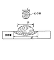
従って、受容層に衝突するインク滴の拡散の全体は、2つの部分、すなわち衝突効果に起因する拡散と、受容層内部の物質移動現象に起因する拡散とで構成される。図1は、受容層の表面上及び受容層の内部へと拡散するインク滴を示す断面図である。衝突前のインク滴直径の初期値に対する受容層上の最終的なドット直径の比によって定義される全体の拡散係数(S)は、単に、衝突の拡散係数(Si)と媒体の拡散係数(Sm)との積であって、すなわち、次式になる。 Thus, the overall diffusion of the ink droplet impinging on the receiving layer is composed of two parts: diffusion due to the collision effect and diffusion due to the mass transfer phenomenon inside the receiving layer. FIG. 1 is a cross-sectional view showing ink droplets diffusing on the surface of the receiving layer and inside the receiving layer. The overall diffusion coefficient (S), defined by the ratio of the final dot diameter on the receiving layer to the initial drop diameter before impact, is simply the diffusion coefficient of impact (S i ) and the diffusion coefficient of the medium (S i ). S m ), that is,
![]()
![]()
ここで、衝突の拡散係数Siは、受容層の表面上における最大のインク滴サイズを決定し、媒体の拡散係数Smは、その後の、受容層におけるさらなるインク滴の拡散を決定する。 Here, the diffusion coefficient S i of the collision determines the maximum drop size on the surface of the receiving layer, and the diffusion coefficient S m of the medium determines the subsequent diffusion of further drops in the receiving layer.
1.衝突の拡散係数(Si).
直径dのインク滴が受容層に衝突すると、インク滴は、衝突直後に、受容層の表面上で最大の直径Diにまで広がる。インク滴の衝突前の直径dに対する衝突後の直径Diの比で定義される衝突の拡散係数Siは、受容層の特性とは独立であって、インク滴のウェーバー数(We)及びレイノルズ数(Re)にのみ依存する。インク滴の直径Diとウェーバー数Weとレイノルズ数Reとを相関させる経験的に得られた式は、アサイほかによって非特許文献2において次式のように与えられた。
1. Diffusion coefficient of collision (S i ).
When the ink droplet diameter d collides with the receiving layer, the ink droplets immediately after the collision extends to a maximum diameter D i on the surface of the receptive layer. The diffusion coefficient S i of the collision, defined as the ratio of the diameter D i after the collision to the diameter d before the collision of the ink droplet, is independent of the properties of the receiving layer and is independent of the Weber number (We) and Reynolds of the ink droplet. It depends only on the number (Re). An empirically obtained equation for correlating the ink droplet diameter Di , the Weber number We, and the Reynolds number Re is given by Asai et al. In Non-Patent Document 2 as follows.

ここで、
数2乃至数4において、a,b及びcは定数であり、vはインク滴の速度であり、ρ,σ及びμは各々インクの密度、表面張力及び粘度である。 に お い て In Equations 2 to 4, a, b and c are constants, v is the velocity of the ink droplet, and ρ, σ and μ are the density, surface tension and viscosity of the ink, respectively.
一般に、衝突の拡散係数は、インク滴の直径及びインク滴の速度が増加すると増大するが、インクの表面張力及び粘度が増大すると低下する。インクの物理的特性(ρ,σ,μ)が与えられると、衝突の拡散係数は、インク滴の直径及びインク滴の速度を変化させることによって制御されうる。実験結果に基づくと、衝突の拡散係数Siの範囲は1.26と4.0の間である。 In general, the diffusion coefficient of a collision increases with increasing drop diameter and drop velocity, but decreases with increasing ink surface tension and viscosity. Given the physical properties of the ink (ρ, σ, μ), the diffusion coefficient of the collision can be controlled by varying the diameter of the ink droplet and the velocity of the ink droplet. Based on experimental results, the range of collision diffusion coefficients S i is between 1.26 and 4.0.
図2は、ウェーバー数Weに対する衝突の拡散係数の依存性を示す。チャイドロンほかによる非特許文献3の測定データに適合するようにアサイのモデルにおいて使用された定数a,b及びcの値は各々、1.48、0.22及び0.29である。このモデルの結果は実験データと非常に良く一致しているということに注意する。 FIG. 2 shows the dependence of the collision diffusion coefficient on the Weber number We. The values of the constants a, b, and c used in the Acai model to fit the measurement data of Chaidron et al., Non-Patent Document 3, are 1.48, 0.22, and 0.29, respectively. Note that the results of this model agree very well with the experimental data.
2.媒体の拡散係数(Sm).
インク滴のサイズ、インク滴の速度及びインクの物理的特性が与えられると、媒体の拡散係数Smは主として、空隙率(多孔性の媒体の場合)及び拡散定数(多孔性ではない媒体の場合)等の媒体の物理的特性に依存する。多孔性の媒体内に拡散するインク滴に対する空隙率の効果については、本発明者らにより、鋭い界面のモデルを使用して詳細に研究されてきた。このようなモデルにおいては、液体で完全に含浸された媒体の領域(又は部分)と、まったく含浸されていない媒体の領域(又は部分)との間の界面が無限に鋭いとみなされる。さらに、インク滴の流体を媒体の中へと引き込む毛細管圧は一定でありかつ媒体の含浸のレベルとは独立であるとされる。このモデルのコンテキストにおいて、本発明者らは、液体の半径方向の最大の拡散を媒体の空隙率の関数として計算した。全体の拡散係数Sは、衝突に起因する半径の相対的な増加率(αi)と、媒体内のインクの移動に起因する半径の相対的な増加率(αm)との項により、次式のように表されうる。
2. Medium diffusion coefficient (S m ).
Given the drop size, drop velocity, and physical properties of the ink, the diffusion coefficient S m of the medium is primarily determined by the porosity (for porous media) and the diffusion constant (for non-porous media). ) Depends on the physical properties of the medium. The effect of porosity on ink droplets diffusing into porous media has been studied in detail by the inventors using a sharp interface model. In such a model, the interface between a region (or portion) of the medium that is completely impregnated with liquid and a region (or portion) of the medium that is not completely impregnated is considered to be infinitely sharp. In addition, the capillary pressure that draws the drop fluid into the media is assumed to be constant and independent of the level of impregnation of the media. In the context of this model, we calculated the maximum radial diffusion of the liquid as a function of the porosity of the medium. The overall diffusion coefficient S is given by the terms of the relative increase rate of the radius (α i ) due to the collision and the relative increase rate of the radius (α m ) due to the movement of the ink in the medium. It can be expressed as an equation.
![]()
![]()
ここで、半径の相対的な増加率αi及びαmは、次式によって、衝突の拡散係数(Si)及び媒体の拡散係数(Sm)に関連付けられる。 Here, the relative increase rates α i and α m of the radii are related to the diffusion coefficient of the collision (S i ) and the diffusion coefficient of the medium (S m ) by:
![]()
![]()
![]()
![]()
図3は、インクで濡らされた半径であって複数の異なる値の半径Rw(すなわち、衝突後のインク滴の半径)について、媒体内の吸着に起因する半径の相対的な増加率(αm)を空隙率の関数として示す。図4は、図3に示されたものと同じデータをプロットしたグラフである。インクで濡らされた半径であって与えられた値の半径においては、空隙率の低下に伴ってインク滴の流体の半径方向の拡散は増大するということに注意する。さらに、与えられた空隙率の媒体では、表面上のインクで濡らされた半径の増大に伴って半径方向の拡散の相対的な増加量は低下する。これらの計算においては、インク滴は単位体積を有するように正規化されている。よって、インク滴の半径(Rd)は、正規化された長さである0.62を有する。インクで濡らされた半径Rw=0.78であれば、半径の相対的な増加率αi=(Rw−Rd)/Rd=0.26となり、かつ衝突の拡散係数Si=1.26となる。 FIG. 3 shows the relative rate of increase of the radius (α) due to adsorption in the medium for a radius R w (ie, the radius of the ink droplet after impact) of the radius wetted with ink and of a plurality of different values. m ) is shown as a function of porosity. FIG. 4 is a graph plotting the same data as shown in FIG. Note that for a given radius of ink wetting, the radial spread of the fluid of the ink droplets increases with decreasing porosity. Further, for a given porosity media, the relative increase in radial diffusion decreases with increasing ink-wetted radius on the surface. In these calculations, the ink drops have been normalized to have a unit volume. Thus, the radius (R d ) of the ink drop has a normalized length of 0.62. If the ink wetted radius R w = 0.78, then the relative increase rate of the radius α i = (R w −R d ) / R d = 0.26 and the collision diffusion coefficient S i = 1.26.
3.コーティングパラメータに対する多孔性の媒体の空隙率の依存性.
コーティングパラメータに対する多孔性の媒体の空隙率の依存性は、次式のように、二成分混合物モデルによって説明することができる。
3. Dependence of porosity of porous media on coating parameters.
The dependence of the porosity of the porous medium on the coating parameters can be described by a binary mixture model as follows:
ここで、
ε=空隙率、
Wc=コーティングの重量、
t=コーティングの厚さ、
ρ1=成分1(有機物)の密度、
ρ2=成分2(無機物)の密度、
f2=成分2(無機物)の質量百分率、
である。
here,
ε = porosity,
W c = weight of coating,
t = coating thickness,
ρ 1 = density of component 1 (organic),
ρ 2 = density of component 2 (inorganic),
f 2 = mass percentage of component 2 (inorganic),
It is.
二成分混合物モデルからの結果は、水銀圧入ポロシメトリ(細孔分布測定)技術を使用して測定された空隙率データと良く一致することが分かっている。さらに、成分2(無機物)の質量百分率f2に関する空隙率εの微分で表された変化と、コーティングの表面積に対する空隙容積又は空隙容量(Vvoid)(以下、空隙容積という。)と、成分2(無機物)の質量百分率f2に関する空隙容積Vvoidの微分で表された変化とは、次式によって与えられる。 The results from the binary mixture model have been found to be in good agreement with porosity data measured using the mercury intrusion porosimetry technique. Further, the change expressed by the derivative of the porosity ε with respect to the mass percentage f 2 of the component 2 (inorganic), the void volume or the void volume (V void ) relative to the surface area of the coating (hereinafter referred to as the void volume), and the component 2 The change expressed by the derivative of the void volume V void with respect to the (inorganic) mass percentage f 2 is given by the following equation.
![]()
![]()
図5及び図6は、それぞれシリカ/PVAコーティング及びヒュームドアルミナ(fumed alumina)/PVAコーティングについて、無機材料の質量百分率(重量パーセント)に対する空隙率と空隙容積(すなわち、表面積に対する空隙容積又は空隙容量。単位:mL/m2(ミリリットル毎平方メートル))の依存性を示す。図5のシリカ/PVAの例の場合、コーティングの重量Wc=25.5g/m2及びコーティングの厚さt=30μmである。図6のヒュームドアルミナ/PVAの例の場合、コーティングの重量Wc=51.2g/m2及びコーティングの厚さt=39μmである。これらの図面は、多孔性コーティングの空隙率及び空隙容積が共に無機成分の質量百分率の線形関数であることを示している。コーティングの重量と、コーティングにおける有機材料に対する無機材料の重量比とを適正に選択すれば、最適な印刷のための所望の空隙率及び空隙容積を得ることができる。 FIGS. 5 and 6 show porosity and void volume (ie, void volume or void volume versus surface area, respectively) for silica / PVA coatings and fumed alumina / PVA coatings, respectively, for the weight percentage of inorganic material. Unit: mL / m 2 (milliliter per square meter). For the silica / PVA example of FIG. 5, the coating weight W c = 25.5 g / m 2 and the coating thickness t = 30 μm. For the example of fumed alumina / PVA of FIG. 6, the coating weight W c = 51.2 g / m 2 and the coating thickness t = 39 μm. These figures show that the porosity and void volume of the porous coating are both linear functions of the mass percentage of the inorganic component. By properly selecting the weight of the coating and the weight ratio of inorganic to organic material in the coating, the desired porosity and void volume for optimal printing can be obtained.
4.凝集しないインクジェット印刷のためのインク滴のサイズ、インク滴の拡散、及び受容層の組成に関する必要条件.
凝集しない印刷を達成するためには、受容層の表面上において、インク滴とその近傍のインク滴との接触を回避する必要がある。印刷の解像度(R)が与えられたとすれば、衝突後の媒体表面上のインク滴のサイズは、画素の間隔(1/R)と、少なくとも21/2/Rである最終的なドットサイズとよりも小さくなるように(図7参照)、すなわち、次式に従って制御される必要がある。
4. Requirements for ink droplet size, ink droplet spreading, and receiving layer composition for non-cohesive inkjet printing.
In order to achieve non-agglomerated printing, it is necessary to avoid contact between the ink droplets and the ink droplets in the vicinity thereof on the surface of the receiving layer. Given the printing resolution (R), the size of the ink drop on the media surface after impact is the pixel spacing (1 / R) and the final dot size that is at least 2 1/2 / R. (See FIG. 7), that is, it is necessary to control according to the following equation.
例えば、インクで濡らされたドットの直径Diに対する安全係数βと、最終的なドットの直径Dに対する安全係数δとがそれぞれ、0.9及び1.0であるように選択されると、必要な媒体の拡散係数(Sm=D/Di)は少なくとも1.57でなければならない。 For example, a safety factor β for the dot diameter D i that is wetted by the ink, the safety factor δ and each relative to the diameter D of the final dot and is selected to be 0.9 and 1.0, need The diffusion coefficient (S m = D / D i ) of a suitable medium must be at least 1.57.
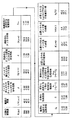
図8は、凝集しない印刷のためのインク滴サイズ、インク滴の拡散、及び受容層の例をそれぞれ示す表である。一例として、印刷の解像度Rは600dpiであり、安全係数β及びδは各々0.9及び1.0であるように選択され、衝突の拡散係数(Si)は1.48であるものと仮定する。図8の表から、凝集しない印刷を達成するためには、必要とされるインク滴の体積Vd、空隙率、及び二成分多孔性コーティング(ヒュームドアルミナ/PVA)におけるヒュームドアルミナの質量百分率(重量パーセント)f2は各々、8.9pL(ピコリットル)、0.26及び46.2%である。 FIG. 8 is a table showing examples of ink droplet size, ink droplet diffusion, and receiving layer for printing without aggregation. As an example, assume that the printing resolution R is 600 dpi, the safety factors β and δ are selected to be 0.9 and 1.0, respectively, and the collision diffusion coefficient (S i ) is 1.48. I do. From the table of FIG. 8, it can be seen that to achieve non-agglomerated printing, the required ink droplet volume Vd, porosity, and mass percentage of fumed alumina in the two-component porous coating (fumed alumina / PVA) ( each wt%) f 2 is, 8.9PL (picoliter), 0.26 and 46.2%.
次に、図9のプリンタシステムを参照すると、インクジェットプリンタシステムは、ページ記述言語の形式であるラスタ画像データ、アウトライン表示された画像データや、あるいは他の形式のディジタル画像データを供給するスキャナ又はコンピュータのような画像ソース10を含む。この画像データは、画像処理装置12によって中間調化された画像データ又は他のビットマップ表示された画像データに変換され、上記画像処理装置もまたメモリに画像データを記憶する。当該技術において公知である複数の制御回路(例えば、インク滴サイズ制御回路)14が提供され、これらは、画像メモリからのデータに応答して、印刷ヘッド16上の回路に対して時間的に変化する電気的パルスを印加し、上記印刷ヘッド16上の回路は、同じく印刷ヘッド16上に配置された各ノズルに関連付けられている。
Referring now to the printer system of FIG. 9, an inkjet printer system is a scanner or computer that supplies raster image data in page description language format, outline-displayed image data, or other types of digital image data. An
上述のように、印刷ヘッドは、ドロップ・オン・デマンド式インクジェットプリンタにおける圧電式に動作されるインク噴射ノズルと、ドロップ・オン・デマンド式インクジェットプリンタにおける熱で動作されるインク噴射ノズルとで構成されることが可能である。 As described above, the print head is composed of a piezoelectrically operated ink jet nozzle in a drop-on-demand ink jet printer and a thermally operated ink jet nozzle in a drop-on-demand ink jet printer. It is possible to
一方で、インクジェット印刷ヘッドは、連続式インクジェット印刷ヘッドとして知られたものであってもよく、上記連続式インクジェット印刷ヘッドではインク小滴が生成され、印刷される画像情報に従って、上記インク小滴の幾分かは受容層媒体の方向へ選択的に方向付けられ、それ以外のインク小滴は受容層媒体に接触することなく選択的に遮断されるか又は除去される。画像データに応答し、制御システムは、印刷される画像データの必要条件に依存して変化するインク滴サイズを提供するように適合化されたものであってもよい。例えば、印刷される各画素に対する画像データは、多くの異なるインク滴サイズを可能にするために1ビットを超える画像データで表現されてもよく、好ましくは、シングルパスモードの印刷における最大サイズのドットであってかつ媒体の多孔性に起因して拡散する前の最大サイズのドットとして、高々1/R未満のサイズまでのドットDiを形成する。さらなる例として、画素毎に4ビットのビット深度である画像データ信号は、最大で16個の異なるインク滴サイズを画成し、よって0から15までの相対的なサイズで画素のサイズを画成することができる。 On the other hand, the inkjet printhead may be what is known as a continuous inkjet printhead, where the continuous inkjet printhead produces ink droplets and, according to the image information to be printed, the ink droplets. Some are selectively directed toward the receiving layer medium, and other ink droplets are selectively blocked or removed without contacting the receiving layer medium. In response to the image data, the control system may be adapted to provide a drop size that varies depending on the requirements of the image data to be printed. For example, the image data for each pixel to be printed may be represented by more than one bit of image data to allow for many different ink drop sizes, preferably the largest size dot in single pass mode printing. as a dot before the maximum size to diffuse due to the porous there are and medium in, to form dots D i of at most up to the size of less than 1 / R. As a further example, an image data signal having a bit depth of 4 bits per pixel defines a maximum of 16 different ink drop sizes, and thus a pixel size with a relative size from 0 to 15. can do.
また、ある画素の場所におけるドットサイズの変化は、シングルパスの間にその画素の場所において多数のインク滴を高速で連続的に堆積させ、媒体の多孔性に起因する拡散よりも前に、サイズが高々1/R未満までのドットサイズDiを有するドットを受容層表面上に形成することによっても提供されうる。他方で、画像データは画素毎に1ビットのみのビット深度によって表現されてもよい。すなわち、ある画素の場所においてインク滴は堆積されるかもしくは堆積されないかのいずれかであり、堆積されたインク滴はすべて実質的に同一サイズである。インクジェットの制御回路は、印刷される画像情報に従ってこれらの異なるインク滴サイズを生成することで知られる。形成されるインク滴が、記録媒体(又は用紙、もしくは受容層媒体)18上において、画像メモリ内のデータによって指定される適正な位置にドットを形成するように、適切な時刻であってかつ適切なノズルに対してパルスが印加される。 Also, a change in dot size at a pixel location can cause a large number of ink droplets to be deposited at that pixel location continuously at a high rate during a single pass, before spreading due to media porosity. There may also be provided by forming a dot having a dot size D i to at most less than 1 / R in the receiving layer on the surface. On the other hand, image data may be represented by a bit depth of only one bit per pixel. That is, ink drops are either deposited or not deposited at a pixel location, and all of the deposited ink drops are substantially the same size. Inkjet control circuits are known to generate these different ink drop sizes according to the image information to be printed. At an appropriate time and at an appropriate time, the formed ink droplet forms a dot on the recording medium (or paper or receiving layer medium) 18 at an appropriate position specified by the data in the image memory. A pulse is applied to the appropriate nozzle.
記録媒体(受容層媒体)18は、記録媒体(又は、用紙もしくは受容層媒体)移送システム20によって印刷ヘッド16に対して相対的に移動され、記録媒体移送システム20は記録媒体(又は、用紙もしくは受容層媒体)移送制御システム22によって電子的に制御され、代わって、記録媒体移送制御システム22はマイクロコントローラ24によって制御される。記録媒体移送システム20は、多くの異なる機械的な構成を採用することが可能である。ページ幅の印刷ヘッド16の場合には、静止した印刷ヘッド16に記録媒体(受容層媒体)18を通して移動させることが最も便利である。しかしながら、走査式印刷システムの場合には、通常は、印刷ヘッド16を一方の軸に沿って(副走査方向)かつ記録媒体18を上記軸に直交した軸に沿って(主走査方向)相対的なラスタ動作で移動させる方がより便利である。もう1つの代替例として、印刷ヘッド16は、ページ全体を含む複数行の画像を同時又は実質上同時に印刷するためのページ全体のサイズの印刷ヘッドのような2次元印刷ヘッドであってもよい。印刷ヘッド16は3行又はそれ以上の行数のノズルを備え、その各行はページ幅の寸法であり、かつ各々が異なる色のインクで印刷し、複数のノズルにてなるこれらの行は実質上同時に動作してもよいということは理解されるであろう。複数のノズルにてなる各行は、1/Rの間隔で互いに均等に離隔配置された一連のノズルを備える。複数のノズルにてなるこれらの行は、同じく1/Rの間隔で隣接する行から離隔配置されてもよい。上述の通り、印刷はシングルパス印刷によって行われ、印刷される画像に関するすべての色は、受容層媒体18に対する印刷ヘッド16のシングルパスによって印刷される。
The recording medium (receiving layer medium) 18 is moved relative to the
インクはインク貯蔵器28に貯蔵され、いくつかの印刷システムにおいてはインク貯蔵器28は加圧下にあってもよい。インクは、インク液路(インクチャンネル)装置30によって印刷ヘッド16の裏面に分配される。インクは、好適には、印刷ヘッド16のシリコン基板を通してエッチングされたスロット及び/又は穴を介して、複数のノズルが配置されたその前面へと流れる。印刷ヘッド16がシリコンで製造される場合、制御回路及び/又は他の回路を印刷ヘッドと一体化することが可能である。
Ink is stored in
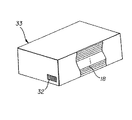
本発明の一態様によれば、マイクロコントローラ24は、上面に印刷されている受容層シートに対する媒体の拡散係数Smに関連した入力信号に応答する。この点に関して、センサ27が、受容層シートの裏側にあってかつ受容層シートの拡散係数Smに関する情報を提供する表示物(又はしるし)を検出するということは、本発明の一態様により認識されるであろう。図10において認識されうるように、表示物31は、バーコード又は他のタイプの印刷された表示物もしくはコーティングされた表示物を備えてもよく、センサ27は、受容層シート18が印刷ステーションへ進入するときにこの表示物を検出するように受容層シートの裏側に近接して配置されてもよい。代替として、図11で参照されるように、表示物32は受容層シートのパッケージ33上に提供され、プリンタによって自動的に検出されるか、もしくは操作者が使用するキーボード、タッチスクリーン又は他の入力制御装置を介して入力されるかのいずれかであってもよい。マイクロコントローラ24は、受容層媒体の拡散係数Smを、本発明の実施形態による特定の媒体上への印刷にとって適正な1つ又は複数のインク滴サイズに対して関連付けるための複数のテーブルを記憶するメモリを含む。これらのテーブルは、その中に、印刷される画像の解像度Rに従ったインク滴サイズの異なる値を記憶していてもよい。
According to one aspect of the present invention, the
本発明の実施形態で使用されるインク及び受容層媒体は、好適には、多孔性材料を介するインクの吸着及び拡散を提供するものであり、拡散は圧力勾配によって生じ、かつ、拡散は実質上、着色剤の濃度勾配が残存していても比較的急速に停止する。多孔性材料は、典型的には厚さ20〜40マイクロメートルであり、支持層(原紙)上にコーティングされていてもされていなくてもよく、かつ媒染剤を含んでいても含んでいなくてもよい。多孔層の厚さは、その中に堆積される所定体積のインクを保持するのに十分な厚さにされる。インク滴のキャリア流体中における染料又は顔料の濃度は、典型的には約1パーセントと3パーセントの間である。これらの層を支持するサポートは、紙又はプラスチック製の透明材料を備えていてもよい。受容層はまた、多孔性材料にてなる複数の層で製造されてもよい。インクを引き寄せるドット又はインクをはじくドットを堆積させるインクジェット印刷ヘッドを使用して印刷板(プリンティング・プレート)を印刷することが知られているので、本発明の実施形態はまた、受容層シート上に印刷するために、印刷板上にそのような液体を堆積させて、上記印刷板が最終的にはそこに選択的にインクを引き寄せるために使用されるということを企図している。 The ink and receptive layer media used in embodiments of the present invention preferably provide for adsorption and diffusion of the ink through the porous material, wherein the diffusion is caused by a pressure gradient and the diffusion is substantially Even if the concentration gradient of the colorant remains, it stops relatively quickly. The porous material is typically 20 to 40 micrometers thick, may or may not be coated on a support layer (base paper) and may or may not contain a mordant. Is also good. The thickness of the porous layer is sufficient to hold a predetermined volume of ink deposited therein. The concentration of the dye or pigment in the ink drop carrier fluid is typically between about 1 percent and 3 percent. The support supporting these layers may comprise a transparent material made of paper or plastic. The receiving layer may also be made of multiple layers of a porous material. Since it is known to print a printing plate (printing plate) using an ink jet print head that deposits ink attracting or ink repelling dots, embodiments of the present invention also include It is contemplated that for printing, such a liquid is deposited on a printing plate, and the printing plate is ultimately used to selectively attract ink thereto.
ゼラチン状の保護膜を有する受容層媒体は、先に引用した従来技術の文献に記載されているように、拡散が続き、かつ典型的には、印刷される受容層媒体をスリーブ(覆い)内に配置したりすることで溶媒のキャリアを乾燥させることによって拡散が停止されるため、本発明には不適である。本発明の実施形態に係る印刷システム及び印刷方法では、印刷された受容層媒体をスリーブ等の吸い取り手段内に配置することは不要である。代わりに、本発明の実施形態は、好適には多孔性コーティング層を有する受容層媒体を採用し、よって、インクの速い移動が存在するような毛細管力に起因して、インクの移動は、多孔性ではない媒体の場合より100乃至1000のオーダーで速くなる傾向がある。多孔性コーティング層を有する媒体は、硬化剤(ジヒドロキシジオクサン(dihydroxydiozane;DHD)等)と共に有機結合剤(ポリビニルアルコール(PVA)等)内に無機物の粒子(ヒュームドアルミナ及びシリカ等)を含み、上にインク滴が堆積される多孔性コーティング層を備えた構造を有する。 Receptive layer media having a gelatinous overcoat, as described in the prior art references cited above, continue to diffuse and typically cause the printed receiving layer media to be placed in a sleeve. For example, it is not suitable for the present invention because the diffusion of the solvent carrier is stopped by drying the solvent carrier. In the printing system and the printing method according to the embodiment of the present invention, it is unnecessary to arrange the printed receiving layer medium in a sucking means such as a sleeve. Instead, embodiments of the present invention preferably employ a receiving layer medium having a porous coating layer, so that due to capillary forces such that there is a fast movement of the ink, the movement of the ink is porous. It tends to be on the order of 100 to 1000 faster than non-sensitive media. The medium having the porous coating layer includes inorganic particles (such as fumed alumina and silica) in an organic binder (such as polyvinyl alcohol (PVA)) together with a curing agent (such as dihydroxydiozane (DHD)); It has a structure with a porous coating layer on which ink drops are deposited.
本発明の実施形態によれば、媒体のインク滴の拡散係数は、好適には21/2<Sm<2×21/2の範囲にあって、ここで21/2は2の平方根又は1.414であり、上記拡散係数は、より好適には1.414<Sm<2.357の範囲にある。最も好適な範囲は、1.414<Sm<1.768である。 According to embodiments of the present invention, the diffusion coefficient of the ink droplets on the medium is preferably in the range 2 1/2 <S m <2 × 2 1/2 , where 2 1/2 is 2 Square root or 1.414, and the diffusion coefficient is more preferably in the range of 1.414 <S m <2.357. The most preferred range is 1.414 <S m <1.768.
好ましい印刷の解像度は、150dpi〜6000dpiの範囲にあり、より好適には300dpi〜2400dpiにあり、最も好適には600dpi〜1200dpiにある。 The preferred printing resolution is in the range of 150 dpi to 6000 dpi, more preferably in the range of 300 dpi to 2400 dpi, and most preferably in the range of 600 dpi to 1200 dpi.
好ましいインク滴の衝突のドットサイズは、好ましくは0.5/R<Di<1/Rの範囲にあり、より好適には0.7/R<Di<0.9/Rの範囲にあり、最も好適には0.8/R<Di<0.9/Rの範囲にある。 The dot size of the ink droplet collision is preferably in the range of 0.5 / R <D i <1 / R, and more preferably in the range of 0.7 / R <D i <0.9 / R. And most preferably in the range 0.8 / R <D i <0.9 / R.
最終的なドットサイズは、好適には21/2/R<D<2.0/Rであり、より好適には1.5/R<D<1.8/Rであり、最も好適には1.1×21/2/R<D<1.7/Rである。 The final dot size is preferably 2 1/2 /R<D<2.0/R, more preferably 1.5 / R <D <1.8 / R, and most preferably. Is 1.1 × 2 1/2 /R<D<1.7/R.
インクドットが中で広がる層の空隙率は、好適には0.2〜0.8の範囲にあり、より好適には0.25〜0.7の範囲にあり、最も好適には0.3〜0.5の範囲にある。空隙率は、層全体の容積に対する層内の空隙の容積の比によって決定される。空隙の容積は、結合剤で結合される無機物の粒子間の隙間である。これは、空隙率の公知の定義である。 The porosity of the layer in which the ink dots extend is preferably in the range of 0.2 to 0.8, more preferably in the range of 0.25 to 0.7, and most preferably 0.3. 0.50.5. Porosity is determined by the ratio of the volume of voids in the layer to the volume of the entire layer. The void volume is the gap between the inorganic particles bound by the binder. This is a known definition of porosity.
本願明細書で説明した様々なパラメータを決定するために、圧電インクジェット印刷ヘッドによってインク滴が周期的に射出され、受容層媒体に対して垂直に衝突させられた。インク滴のサイズ及び速度は、印刷ヘッドに印加される電気的パルスによって制御された。インク滴の振るまいを観測するために使用された装置は、静止画像及びビデオレート画像の両方の取得をサポートするための、顕微鏡と、CCDカメラと、駆動パルスに同期化されたストロボ光源と、画像生成光学装置と、受容層媒体移送用並進ステージと、モニタと、画像取得用ハードウェア及びソフトウェアとを含んでいる。照明の遅延を変化させることによって、拡散現象の異なる段階が観測された。受容層媒体との衝突直後のインク滴のサイズ(Di)が測定され、既知の長さに照らして校正される。 To determine the various parameters described herein, ink drops were periodically ejected by a piezoelectric inkjet printhead and impacted perpendicularly to the receiving layer media. The size and speed of the ink droplets were controlled by electrical pulses applied to the print head. The equipment used to observe the behavior of the ink drops included a microscope, a CCD camera, and a strobe light source synchronized with a drive pulse to support the acquisition of both still and video rate images. It includes an imaging optics, a translation stage for transporting the receiving layer media, a monitor, and hardware and software for image acquisition. By varying the illumination delay, different stages of the diffusion phenomenon were observed. The size (D i ) of the ink drop immediately after impact with the receiving layer medium is measured and calibrated against a known length.
媒体に衝突する前のインク滴のサイズ(d)は、既知の多数(百万個単位)のインク滴が印刷ヘッドから発射され、発射されたインク滴の目標となる容器に付加された重量を測定することによって決定可能である。インク滴は、印刷ヘッドから受容層媒体までの自由飛行においては球であることが仮定され、既知の密度を有する。従って、インク滴のサイズ(d)を計算することができる。最終的なドットサイズ(D)は、単離した単一のインク滴を媒体上に噴射することにより、顕微鏡を用いて測定することができる。 The size (d) of the ink drop before impacting the media is determined by the known mass (in the millions) of ink drops fired from the printhead and the weight added to the target container for the fired ink drops. It can be determined by measuring. The ink drops are assumed to be spherical in free flight from the printhead to the receiving layer media and have a known density. Therefore, the size (d) of the ink droplet can be calculated. The final dot size (D) can be measured using a microscope by ejecting a single isolated ink droplet onto the medium.
ドットサイズの測定手順について記述している参考文献は、(1)非特許文献4と、(2)非特許文献5とを含む。 References describing the dot size measurement procedure include (1) Non-Patent Document 4 and (2) Non-Patent Document 5.
空隙率は、物質の「開口度(openness)」と呼ばれる、物質内の空気を含む空間のサイズ及び個数である。特に空隙率は、固体の全体の体積に対する開いた空隙の体積の比として定義される。一般に多孔性材料の空隙率は、「水銀圧入法」によって正確に測定可能である。本方法については、非特許文献6に詳述されている。測定原理は、下記の通りである。 Porosity is the size and number of air-containing spaces in a material, called the “openness” of the material. In particular, porosity is defined as the ratio of the volume of open porosity to the total volume of the solid. Generally, the porosity of a porous material can be accurately measured by the “mercury intrusion method”. This method is described in detail in Non-Patent Document 6. The measurement principle is as follows.
サンプル/非湿潤性液体表面の自由エネルギーはサンプル/気体表面の自由エネルギーより大きいことから、水銀のような非湿潤性の液体はサンプル中の空隙を自発的には充填しない。しかしながら、圧力をかければ、非湿潤性の液体をサンプル中の空隙へ押し込むことができる。非湿潤性の液体を空隙へ押し込むために必要な差圧は、次式のウォッシュバーン(Washburn)の式によって与えられる。 Non-wetting liquids, such as mercury, do not spontaneously fill voids in the sample because the free energy of the sample / non-wetting liquid surface is greater than the free energy of the sample / gas surface. However, under pressure, a non-wetting liquid can be forced into the voids in the sample. The differential pressure required to force a non-wetting liquid into the void is given by the Washburn equation:
![]()
![]()
ここで、Δp=差圧であり、σは非湿潤性液体の表面張力であり、θはサンプルに対する非湿潤性液体の接触角度であり、r=空隙の半径である。 Where Δp = differential pressure, σ is the surface tension of the non-wetting liquid, θ is the contact angle of the non-wetting liquid to the sample, and r is the radius of the void.
この技術では、圧入される非湿潤性液体の圧力及び容積が正確に測定される。これらのデータを表面張力、液体の接触角度及びサンプルの厚さと組み合わせて、空隙の半径、空隙容積の分布、空隙の表面積及び空隙率が計算される。 技術 This technique accurately measures the pressure and volume of the non-wetting liquid to be injected. These data are combined with surface tension, liquid contact angle and sample thickness to calculate the void radius, void volume distribution, void surface area and porosity.
典型的なポロシメータ(細孔分布測定器)は、14850ニューヨーク州、イサカ、ブラウン・ロード83番のポーラス・マテリアルズ・インコーポレイテッド(Porous Materials, Inc.)により、型番AMP−200−A−1として製造されている。 A typical porosimeter (Porosimeter) is available from Porous Materials, Inc., Brown Road 83, Ithaca, NY 14850, model number AMP-200-A-1. Being manufactured.
本願明細書で言及されたインクは、染料をベースとするインクであってもよく、特に、顔料の粒子が受容層の最上層を介して移動して拡散できるように、顔料が受容層の最上層の空隙のサイズの半分未満(好適には、受容層の最上層の空隙のサイズの10分の1未満)の粒子サイズを有するときには、顔料を含むインクであってもよい。 The inks referred to herein may be dye-based inks, particularly where the pigment is located on the top of the receiving layer so that the pigment particles can migrate and diffuse through the top layer of the receiving layer. An ink containing a pigment may be used if it has a particle size of less than half the size of the voids in the upper layer (preferably less than one-tenth the size of the voids in the uppermost layer of the receiving layer).
インク又は使用される印刷用液体の表面張力及び粘度は、典型的には印刷ヘッドのタイプ、すなわち、熱式、圧電式、連続式と、印刷ヘッドのタイプのこれらの分類内での変形物とに関連する。 The surface tension and viscosity of the ink or the printing liquid used are typically determined by the type of printhead, i.e., thermal, piezoelectric, continuous, and variants within these categories of printhead type. is connected with.
一般に、これらのインク又は印刷用液体は、1乃至8cP(センチポアズ)の範囲の粘度と、10乃至50ダイン/cmの範囲の表面張力とを有する。 Generally, these inks or printing liquids have a viscosity in the range of 1 to 8 cP (centipoise) and a surface tension in the range of 10 to 50 dynes / cm.
インク又は印刷用液体の液滴の体積は、0.1pL乃至128pLの範囲である可能性がある。本願明細書で説明した階調印刷の議論に一致して、ある画素の場所における最終的なインク滴のサイズは、その画素の場所で複数のインク滴を堆積させることにより生成することができる。 体積 The volume of the ink or printing liquid droplet can range from 0.1 pL to 128 pL. Consistent with the tone printing discussion described herein, the final drop size at a pixel location can be generated by depositing multiple drops at that pixel location.
インク滴が拡散する画像受容層は、0.2乃至0.8の空隙率の範囲で20乃至150ミクロンの厚さを有してもよい。 The image receiving layer over which the ink droplets diffuse may have a thickness of 20 to 150 microns with a porosity in the range of 0.2 to 0.8.
以上、凝集しないシングルパスインクジェット印刷のための新規な印刷方法及びプリンタシステムについて説明した。本方法及びシステムは、凝集が受容層表面におけるインク滴とその隣接するインク滴との接触に起因するという事実を利用している。インク滴の接触を回避するためには、衝突後の受容層表面でのインク滴サイズがピクセル間隔(1/R)より小さくなるように制御される必要があり、最終的なドットサイズが21/2/Rより大きくなるように制御される必要がある。ここで、Rは印刷の解像度である。衝突後の受容層表面でのインク滴サイズは、衝突前のインク滴サイズの初期値とインク滴の速度との適正な選択によって制御可能である。物質移動現象に起因して受容層内に拡散するインク滴は、多孔性媒体の空隙率のような受容層特性の適正な選択によって制御可能である。二成分媒体の空隙率は、コーティングの重量と、コーティングにおける有機材料に対する無機材料の比との適正な選択によって制御可能である。この凝集しない新規な印刷技術は印刷速度とは独立したものであり、生産性を犠牲にすることなくシングルパス印刷に適用可能である。 The novel printing method and printer system for single-pass inkjet printing without aggregation have been described above. The method and system take advantage of the fact that agglomeration is due to the contact of an ink drop at the surface of the receiving layer with an adjacent ink drop. In order to avoid contact of the ink droplet, it is necessary to drop sizes in the receiving layer surface after a collision is controlled to be smaller than the pixel spacing (1 / R), the final dot size 2 1 It needs to be controlled to be larger than / 2 / R. Here, R is the printing resolution. The size of the ink droplets on the surface of the receiving layer after the collision can be controlled by appropriate selection of the initial value of the ink droplet size before the collision and the speed of the ink droplets. Ink droplets that diffuse into the receiving layer due to mass transfer phenomena can be controlled by proper selection of receiving layer properties such as porosity of the porous medium. The porosity of the binary media can be controlled by the proper choice of the weight of the coating and the ratio of inorganic to organic material in the coating. This new non-agglomerated printing technique is independent of printing speed and can be applied to single pass printing without sacrificing productivity.
10…画像ソース、
12…画像処理装置、
14…インク滴サイズ制御回路、
16…印刷ヘッド、
18…記録媒体、
20…記録媒体移送システム、
22…記録媒体移送制御システム、
24…マイクロコントローラ、
27…センサ、
28…インク貯蔵器、
30…インク液路装置、
31,32…表示物、
33…パッケージ。
10. Image source,
12 ... Image processing device,
14 ... ink drop size control circuit,
16 print head,
18 recording medium,
20: recording medium transport system,
22 ... recording medium transfer control system
24 ... microcontroller,
27 ... Sensor,
28 ... Ink reservoir,
30 ... ink liquid passage device,
31, 32 ... display objects,
33… Package.
Claims (5)
複数のノズルを有する印刷ヘッド(16)を備え、上記印刷ヘッド(16)は、画像を形成する際に使用される液体インク又は他の液体の液滴をシングルパス印刷モードで受容層媒体(18)の表面上に堆積させるために選択的に動作可能であり、このとき、印刷の解像度がRであり、上記受容層媒体(18)に対する上記液滴の衝突から結果的に生じるドットのドットサイズDiが0.5/R<Di<1/Rの範囲にあり、上記表面上に拡散した後の最終的なドットサイズDが21/2/R<D<2.0/Rの範囲にあるように上記液滴は上記表面上に堆積され、
上記受容層媒体(18)は上記液滴を受容するための表面を有し、上記表面に近接する上記受容層媒体の部分は液滴の拡散に対する影響を有し、上記部分は、Sm=D/Diかつ21/2<Sm<2×21/2として、媒体の液滴の拡散係数Smを提供するのに十分な0.2乃至0.8の範囲の空隙率を有することを特徴とするインクジェットプリンタシステム。 An inkjet printer system for recording an image in a single-pass print mode,
A print head (16) having a plurality of nozzles, wherein the print head (16) applies droplets of liquid ink or other liquid used in forming an image in a single pass printing mode to a receiving layer medium (18). ) Is selectively operable to deposit on the surface of the substrate, where the printing resolution is R and the dot size of the dots resulting from the impact of the droplets on the receiving layer media (18). D i is 0.5 / R <is in the range of D i <1 / R, the final dot size D after spreading on the surface of the 2 1/2 /R<D<2.0/R The droplets are deposited on the surface to be in range,
The receiving layer medium (18) has a surface for receiving the droplets, a portion of the receiving layer medium proximate to the surface having an effect on droplet spreading, wherein the portion has a S m = Assuming that D / D i and 2 1/2 <S m <2 × 2 1/2 , the porosity in the range of 0.2 to 0.8 is sufficient to provide the diffusion coefficient S m of the droplet of the medium. An inkjet printer system comprising:
画像を形成する際に使用される液体インク又は他の液体の液滴は、印刷の解像度がRであり、上記受容層媒体(18)に対する上記液滴の衝突から結果的に生じるドットのドットサイズDiが0.5/R<Di<1/Rの範囲にあり、上記受容層媒体(18)の表面上に拡散した後の最終的なドットサイズDが21/2/R<D<2.0/Rの範囲にあるように、シングルパス印刷モードで上記受容層媒体(18)上に堆積され、
上記受容層媒体(18)は上記液滴を受容するための表面を有し、上記表面に近接する上記受容層媒体の部分は液滴の拡散に対する影響を有し、上記部分は、Sm=D/Diかつ21/2<Sm<2×21/2として、媒体の液滴の拡散係数Smを提供するのに十分な0.2乃至0.8の範囲の空隙率を有し、
上記受容層媒体(18)又はそのパッケージ(33)は、そこに付随しかつ上記媒体の液滴の拡散係数Smに関連する表示物(31,32)を含むことを特徴とする受容層媒体(18)又はそのパッケージ(33)。 Receptive layer media (18) or its package (33) for use in an ink jet printer system, comprising:
The droplet of liquid ink or other liquid used in forming the image has a printing resolution of R and the dot size of the dots resulting from the impact of the droplet on the receiving layer media (18). Di is in the range of 0.5 / R <D i <1 / R, and the final dot size D after diffusion on the surface of the receiving layer medium (18) is 2 1/2 / R <D. Deposited on the receiving layer media (18) in single pass printing mode to be in the range of <2.0 / R;
The receiving layer medium (18) has a surface for receiving the droplets, a portion of the receiving layer medium proximate to the surface having an effect on droplet spreading, wherein the portion has a S m = Assuming that D / D i and 2 1/2 <S m <2 × 2 1/2 , the porosity in the range of 0.2 to 0.8 is sufficient to provide the diffusion coefficient S m of the droplet of the medium. Have
Said receptive layer medium (18) or its packaging (33), the receiving layer medium, which comprises a thereto associated and display object related to the diffusion coefficient S m of the droplets of said medium (31, 32) (18) or its package (33).
画像を形成する際に使用される液体インク又は他の液体の液滴をシングルパスで受容層媒体の表面上に堆積させるために選択的に動作可能な複数のノズルを有する印刷ヘッド(16)を備え、このとき、印刷の解像度がRであり、上記受容層媒体に対する上記液滴の衝突から結果的に生じるドットのドットサイズDiが0.5/R<Di<1/Rの範囲にあり、上記表面上に拡散した後の最終的なドットサイズDが21/2/R<D<2.0/Rの範囲にあるように上記液滴は上記表面上に堆積され、
上記シングルパスインクジェットプリンタは、
上記受容層媒体に付随しかつ媒体の液滴の拡散係数Smに関連する表示物を表す信号を受信するための入力(24,27)を備え、ここで、Sm=D/Diであり、Dは上記シングルパスインクジェットプリンタによって印刷された後の上記受容層媒体上の最終的なドットサイズであり、Diは、上記受容層媒体上に堆積され、上記受容層媒体との衝突から結果として生じる液滴のドットサイズであることを特徴とするシングルパスインクジェットプリンタ。 A single-pass inkjet printer,
A print head (16) having a plurality of nozzles selectively operable to deposit droplets of a liquid ink or other liquid used in forming an image on a surface of a receiving layer medium in a single pass. provided, this time, a resolution of the print is R, the range of the dot size D i is 0.5 / R <D i <1 / R of the resulting dots from the collision of the droplet with respect to the receiving layer medium The droplets are deposited on the surface such that the final dot size D after diffusion on the surface is in the range of 2 1/2 /R<D<2.0/R;
The single pass inkjet printer is
An input (24, 27) for receiving a signal representing the display object associated with the diffusion coefficient S m of the droplets of the receiving layer associated with the medium and the medium, wherein, in S m = D / D i Where D is the final dot size on the receiving layer media after being printed by the single-pass inkjet printer, and Di is deposited on the receiving layer media and from the impact with the receiving layer media. A single-pass inkjet printer characterized by the resulting droplet dot size.
複数のノズルを有する印刷ヘッドを提供することと、
上記印刷ヘッドを選択的に動作させて、画像を形成する際に使用される液体インク又は他の液体の液滴をシングルパス印刷モードで受容層媒体の表面上に堆積させることとを含み、このとき、印刷の解像度がRであり、上記受容層媒体に対する上記液滴の衝突から結果的に生じるドットのドットサイズDiが0.5/R<Di<1/Rの範囲にあり、上記表面上に拡散した後の最終的なドットサイズDが少なくとも21/2/R<D<2.0/Rの範囲にあるように上記液滴は上記表面上に堆積され、
上記受容層媒体は上記液滴を受容するための表面を有し、上記表面に近接する上記受容層媒体の部分は上記液滴の拡散に対する影響を有し、上記部分は、Sm=D/Diかつ21/2<Sm<2×21/2として、媒体の液滴の拡散係数Smを提供するのに十分な0.2乃至0.8の範囲の空隙率を有することを特徴とするインクジェット印刷方法。 An inkjet printing method for recording an image in a single-pass print mode,
Providing a print head having a plurality of nozzles;
Selectively operating the printhead to deposit droplets of liquid ink or other liquid used in forming an image on a surface of the receiving layer media in a single pass printing mode. when the resolution of the print is R, the dot size D i of the resulting dots from the collision of the droplet with respect to the receiving layer medium is in the range of 0.5 / R <D i <1 / R, the The droplets are deposited on the surface such that the final dot size D after spreading on the surface is at least in the range of 2 1/2 /R<D<2.0/R;
The receiving layer medium has a surface for receiving the droplets, a portion of the receiving layer medium proximate to the surface having an effect on the spreading of the droplets, wherein the portion has S m = D / as D i and 2 1/2 <S m <2 × 2 1/2, having a porosity in the range of sufficient 0.2 to 0.8 to provide a diffusion coefficient S m of the droplets of medium An inkjet printing method characterized by the above-mentioned.
複数のノズルを有する印刷ヘッドを提供することと、
上記印刷ヘッドを選択的に動作させて、画像を形成する際に使用される液体インク又は他の液体の液滴をシングルパスで受容層媒体の表面上に堆積させることとを含み、このとき、印刷の解像度がRであり、上記受容層媒体に対する上記液滴の衝突から結果的に生じるドットのドットサイズDiが0.5/R<Di<1/Rの範囲にあり、上記表面上に拡散した後の最終的なドットサイズDが21/2/R<D<2.0/Rの範囲にあるように上記液滴は上記表面上に堆積され、
上記インクジェット印刷方法は、
上記受容層媒体に付随しかつ媒体の液滴の拡散係数Smに関連する表示物を表す信号を提供することを含み、ここで、Sm=D/Diであり、Dはインクジェットプリンタによって印刷された後の上記受容層媒体上の最終的なドットサイズであり、Diは、上記受容層媒体上に堆積され、上記受容層媒体との衝突から結果として生じる液滴のドットサイズであり、
上記インクジェット印刷方法は、
上記信号に応答して、上記複数のノズルから放出される液滴の1つ又は複数の液滴サイズを制御することを含むことを特徴とするインクジェット印刷方法。
An inkjet printing method,
Providing a print head having a plurality of nozzles;
Selectively operating the printhead to deposit a drop of liquid ink or other liquid used in forming an image on the surface of the receiving layer medium in a single pass, a resolution of the print is R, the dot size D i of relative receiving layer medium from the collision of the droplet the resulting dot is in the range of 0.5 / R <D i <1 / R, the upper surface The droplets are deposited on the surface such that the final dot size D after diffusion to the surface is in the range of 2 1/2 /R<D<2.0/R,
The inkjet printing method,
Comprising: providing a signal representing the display object associated with the diffusion coefficient S m of the droplets of concomitant and medium to the receiving layer medium, wherein a S m = D / D i, D is the ink jet printer The final dot size on the receiving layer media after printing, Di is the dot size of the droplets deposited on the receiving layer media and resulting from impact with the receiving layer media. ,
The inkjet printing method,
An inkjet printing method, comprising controlling one or more droplet sizes of droplets ejected from the plurality of nozzles in response to the signal.
Applications Claiming Priority (1)
| Application Number | Priority Date | Filing Date | Title |
|---|---|---|---|
| US10/252,312 US6702425B1 (en) | 2002-09-23 | 2002-09-23 | Coalescence-free inkjet printing by controlling drop spreading on/in a receiver |
Publications (2)
| Publication Number | Publication Date |
|---|---|
| JP2004114688A true JP2004114688A (en) | 2004-04-15 |
| JP2004114688A5 JP2004114688A5 (en) | 2006-08-17 |
Family
ID=31887852
Family Applications (1)
| Application Number | Title | Priority Date | Filing Date |
|---|---|---|---|
| JP2003331860A Pending JP2004114688A (en) | 2002-09-23 | 2003-09-24 | Inkjet printer system and inkjet printing method |
Country Status (3)
| Country | Link |
|---|---|
| US (1) | US6702425B1 (en) |
| EP (1) | EP1400359A3 (en) |
| JP (1) | JP2004114688A (en) |
Cited By (2)
| Publication number | Priority date | Publication date | Assignee | Title |
|---|---|---|---|---|
| WO2009157262A1 (en) | 2008-06-23 | 2009-12-30 | コニカミノルタホールディングス株式会社 | Inkjet recording device and inkjet recording method |
| JP2010119991A (en) * | 2008-11-21 | 2010-06-03 | Seiko Epson Corp | Method for evaluating amount of liquid droplet to be discharged from apparatus for discharging liquid droplet |
Families Citing this family (22)
| Publication number | Priority date | Publication date | Assignee | Title |
|---|---|---|---|---|
| US7108434B2 (en) * | 2004-01-21 | 2006-09-19 | Silverbrook Research Pty Ltd | Method for printing wallpaper |
| US7186042B2 (en) | 2004-01-21 | 2007-03-06 | Silverbrook Research Pty Ltd | Wallpaper printer |
| KR101211016B1 (en) * | 2004-09-07 | 2012-12-11 | 후지필름 디마틱스, 인크. | Variable resolution in printing system and method |
| JP4483774B2 (en) * | 2005-12-06 | 2010-06-16 | ブラザー工業株式会社 | Package material |
| JP2008049563A (en) * | 2006-08-23 | 2008-03-06 | Canon Inc | Image processor, image recorder and recording data forming method |
| GB0620618D0 (en) * | 2006-10-17 | 2006-11-29 | Xaar Technology Ltd | Method of preventing the formation of inkjet printing artefacts |
| US20090002422A1 (en) * | 2007-06-29 | 2009-01-01 | Stephenson Iii Stanley W | Structure for monolithic thermal inkjet array |
| US20110043582A1 (en) * | 2009-08-21 | 2011-02-24 | Silverbrook Research Pty Ltd | Continuous web printer with automated web threading mechanism |
| EP2761377A1 (en) | 2011-09-27 | 2014-08-06 | Eastman Kodak Company | Inkjet printing using large particles |
| US8761652B2 (en) | 2011-12-22 | 2014-06-24 | Eastman Kodak Company | Printer with liquid enhanced fixing system |
| US8764180B2 (en) | 2011-12-22 | 2014-07-01 | Eastman Kodak Company | Inkjet printing method with enhanced deinkability |
| US8814292B2 (en) | 2011-12-22 | 2014-08-26 | Eastman Kodak Company | Inkjet printer for semi-porous or non-absorbent surfaces |
| US8807730B2 (en) | 2011-12-22 | 2014-08-19 | Eastman Kodak Company | Inkjet printing on semi-porous or non-absorbent surfaces |
| US8770701B2 (en) | 2011-12-22 | 2014-07-08 | Eastman Kodak Company | Inkjet printer with enhanced deinkability |
| US8857937B2 (en) | 2011-12-22 | 2014-10-14 | Eastman Kodak Company | Method for printing on locally distorable mediums |
| US8864255B2 (en) | 2011-12-22 | 2014-10-21 | Eastman Kodak Company | Method for printing with adaptive distortion control |
| US8791971B2 (en) | 2012-07-12 | 2014-07-29 | Eastman Kodak Company | Large-particle inkjet dual-sign development printing |
| US8717395B2 (en) | 2012-07-12 | 2014-05-06 | Eastman Kodak Company | Large-particle inkjet receiver-charging intermediate member |
| JP6102308B2 (en) * | 2013-02-15 | 2017-03-29 | セイコーエプソン株式会社 | Ink jet recording method and ink jet recording apparatus |
| US20170045427A1 (en) * | 2014-02-20 | 2017-02-16 | The Arizona Board Of Regents On Behalf Of The University Of Arizona | Method for guiding cell spreading in automated cytogenetic assays |
| US11001056B2 (en) * | 2015-04-20 | 2021-05-11 | Koninklijke Philips N.V. | Printing control device to control printing of a cover layer on a sample |
| US11203207B2 (en) * | 2015-12-07 | 2021-12-21 | Kateeva, Inc. | Techniques for manufacturing thin films with improved homogeneity and print speed |
Family Cites Families (13)
| Publication number | Priority date | Publication date | Assignee | Title |
|---|---|---|---|---|
| US3946398A (en) | 1970-06-29 | 1976-03-23 | Silonics, Inc. | Method and apparatus for recording with writing fluids and drop projection means therefor |
| CA1127227A (en) | 1977-10-03 | 1982-07-06 | Ichiro Endo | Liquid jet recording process and apparatus therefor |
| CA1158706A (en) | 1979-12-07 | 1983-12-13 | Carl H. Hertz | Method and apparatus for controlling the electric charge on droplets and ink jet recorder incorporating the same |
| US4914451A (en) | 1987-06-01 | 1990-04-03 | Hewlett-Packard Company | Post-printing image development of ink-jet generated transparencies |
| US4748453A (en) | 1987-07-21 | 1988-05-31 | Xerox Corporation | Spot deposition for liquid ink printing |
| US5188664A (en) | 1991-11-26 | 1993-02-23 | Hewlett-Packard Company | Anti-coalescent ink composition and method for making the same |
| JP3303901B2 (en) | 1994-09-16 | 2002-07-22 | セイコーエプソン株式会社 | Electric field drive type ink jet recording head and driving method thereof |
| EP0730973B2 (en) * | 1995-03-06 | 2010-11-17 | Canon Kabushiki Kaisha | Recording apparatus and method |
| US5880759A (en) | 1995-04-12 | 1999-03-09 | Eastman Kodak Company | Liquid ink printing apparatus and system |
| JPH10244692A (en) | 1997-03-05 | 1998-09-14 | Minolta Co Ltd | Ink jet recorder |
| US6079821A (en) | 1997-10-17 | 2000-06-27 | Eastman Kodak Company | Continuous ink jet printer with asymmetric heating drop deflection |
| EP1122074B1 (en) * | 2000-02-03 | 2006-04-12 | Canon Kabushiki Kaisha | Inks-and-printing-media-integrated pack, ink-jet printing apparatus and method |
| US6663221B2 (en) | 2000-12-06 | 2003-12-16 | Eastman Kodak Company | Page wide ink jet printing |
-
2002
- 2002-09-23 US US10/252,312 patent/US6702425B1/en not_active Expired - Fee Related
-
2003
- 2003-09-11 EP EP03077855A patent/EP1400359A3/en not_active Withdrawn
- 2003-09-24 JP JP2003331860A patent/JP2004114688A/en active Pending
Cited By (3)
| Publication number | Priority date | Publication date | Assignee | Title |
|---|---|---|---|---|
| WO2009157262A1 (en) | 2008-06-23 | 2009-12-30 | コニカミノルタホールディングス株式会社 | Inkjet recording device and inkjet recording method |
| US8454152B2 (en) | 2008-06-23 | 2013-06-04 | Konica Minolta Holdings, Inc. | Ink jet recording device and ink jet recording method |
| JP2010119991A (en) * | 2008-11-21 | 2010-06-03 | Seiko Epson Corp | Method for evaluating amount of liquid droplet to be discharged from apparatus for discharging liquid droplet |
Also Published As
| Publication number | Publication date |
|---|---|
| US6702425B1 (en) | 2004-03-09 |
| EP1400359A2 (en) | 2004-03-24 |
| EP1400359A3 (en) | 2004-12-15 |
Similar Documents
| Publication | Publication Date | Title |
|---|---|---|
| JP2004114688A (en) | Inkjet printer system and inkjet printing method | |
| Le | Progress and trends in ink-jet printing technology | |
| US5896155A (en) | Ink transfer printing apparatus with drop volume adjustment | |
| US6022099A (en) | Ink printing with drop separation | |
| JP3802616B2 (en) | Inkjet recording method | |
| US8215744B2 (en) | Image forming method and image forming apparatus | |
| JPH06297717A (en) | Ink jet recording method and head | |
| US7883201B2 (en) | Image forming apparatus and image forming method | |
| JP2001018380A (en) | Apparatus for forming texture layer on image | |
| JP2004114688A5 (en) | ||
| JPH09169117A (en) | Cmos process interchange manufacture of print head | |
| EP0913259A3 (en) | Apparatus for generating small volume, high velocity ink droplets in an inkjet printer | |
| US6498615B1 (en) | Ink printing with variable drop volume separation | |
| US20050212854A1 (en) | Liquid discharge head, liquid discharge recording apparatus and liquid discharge recording method | |
| JP6079318B2 (en) | Ink set, recording method and recording apparatus | |
| JPH10501491A (en) | Liquid ink printing device and system | |
| JP2006205612A (en) | Ink-jet printer having mechanism for preventing adhesion of volatile material | |
| JP3667076B2 (en) | Inkjet recording method and inkjet recording apparatus | |
| JP2804563B2 (en) | Inkjet recording method | |
| JP3384797B2 (en) | Ink jet recording head and ink jet recording apparatus | |
| JP3312894B2 (en) | Ink jet recording method and ink jet recording apparatus | |
| US20050068347A1 (en) | Three-dimensional image forming method | |
| JP3380811B2 (en) | Inkjet recording head | |
| JPH09193399A (en) | Method and device for ink jet recording | |
| JPH05116313A (en) | Ink jet recording method |
Legal Events
| Date | Code | Title | Description |
|---|---|---|---|
| A521 | Written amendment |
Free format text: JAPANESE INTERMEDIATE CODE: A523 Effective date: 20060628 |
|
| A621 | Written request for application examination |
Free format text: JAPANESE INTERMEDIATE CODE: A621 Effective date: 20060628 |
|
| RD03 | Notification of appointment of power of attorney |
Free format text: JAPANESE INTERMEDIATE CODE: A7423 Effective date: 20080131 |
|
| A977 | Report on retrieval |
Free format text: JAPANESE INTERMEDIATE CODE: A971007 Effective date: 20081107 |
|
| A131 | Notification of reasons for refusal |
Free format text: JAPANESE INTERMEDIATE CODE: A131 Effective date: 20081111 |
|
| A02 | Decision of refusal |
Free format text: JAPANESE INTERMEDIATE CODE: A02 Effective date: 20090507 |