JP2004113476A - Body hair treatment device and wire heater cartridge - Google Patents
Body hair treatment device and wire heater cartridge Download PDFInfo
- Publication number
- JP2004113476A JP2004113476A JP2002281115A JP2002281115A JP2004113476A JP 2004113476 A JP2004113476 A JP 2004113476A JP 2002281115 A JP2002281115 A JP 2002281115A JP 2002281115 A JP2002281115 A JP 2002281115A JP 2004113476 A JP2004113476 A JP 2004113476A
- Authority
- JP
- Japan
- Prior art keywords
- current
- metal plate
- carrying
- wire
- energizing
- Prior art date
- Legal status (The legal status is an assumption and is not a legal conclusion. Google has not performed a legal analysis and makes no representation as to the accuracy of the status listed.)
- Ceased
Links
Images


Landscapes
- Surgical Instruments (AREA)
Abstract
Description
【0001】
【発明の属する技術分野】
本発明は、ビキニラインや腋、脚・腕などの気になるムダ毛の処理、調髪などの際に使用する体毛処理具に関する。
【0002】
【従来の技術】
例えばハイレグ水着やレオタードの着用前などのムダ毛の処理に鋏や剃刀などの刃物を用いると、切り整えた毛先は刃物による剪断のために尖鋭で、その尖り毛先が布地を容易に突き通って外側へのぞくことがあったり、また触りがいたみのあるものとなったりする。
【0003】
そこで本出願人は、毛先に丸みをもたせて体毛を切り整えることができる体毛処理具として、通電発熱線で体毛を焼き切るヒートカット構成のものを考案し、実用化している(例えば、特許文献1〜9参照)。
【0004】
これは、5〜10mm程度の間隔を開けて側面を対向させて並設した2枚の対向くし歯板部と、該2枚の対向くし歯板部の間に配設されてくし歯板部のくし歯に梳き入れた体毛に接触するとともに通電されることで赤熱して該接触体毛を焼き切る通電発熱線、具体的にはニクロムワイヤとを基本構造とするものである。
【0005】
体毛は赤熱状態のニクロムワイヤに接すると簡単に焼け切れる。焼き切られた体毛の毛先は刃物で剪断した場合とは異なり尖鋭とならず、丸みのあるものとなり、刃物による場合のような不具合を生じない。
【0006】
また理髪・美容術の調髪器具として用いて有効である。即ち調髪した毛先部にニクロムワイヤ部分を接触摺動して焼き切り状態に処理することで毛先に丸みや微妙なカーブ若しくは縮れを生じさせて調髪に独特の風合いを与えることができる。
【0007】
ニクロムワイヤの断線時の対処・修復の容易性を考慮して、ニクロムワイヤは体毛処理具本体に対して容易に抜き差し交換自在としたワイヤヒータカートリッジの第1と第2の通電用電極部間に張り渡して具備させてあり、ニクロムワイヤの断線時は新品のカートリッジと差し替えることができるようになっている。
【0008】
カートリッジが体毛処理具本体に装着された状態において、カートリッジ側の電気接点部材と体毛処理具本体側の電気接点部材が接触していて、体毛処理具本体側からカートリッジ側のニクロムワイヤへの給電が可能となる。
【0009】
また、体毛処理具本体側に板バネ等の弾性付勢部材を具備させ、カートリッジが体毛処理具本体に装着された状態において、弾性付勢部材によりニクロムワイヤに常時張力が作用するようにして、ニクロムワイヤの発熱時の熱膨張による伸びたるみを吸収させるようにしてある。
【特許文献1】
実公平4−037521号公報
【特許文献2】
実公平6−014649号公報
【特許文献3】
登録実用新案第3006125号公報
【特許文献4】
特許第3109455号明細書
【特許文献5】
特許第3147816号明細書
【特許文献6】
意匠登録第857135号公報
【特許文献7】
特開平8−289814号公報
【特許文献8】
特開平9−248212号公報
【特許文献9】
特開2000−83723号公報
【0010】
【発明が解決しようとする課題】
従来品において、通電発熱線としてのニクロムワイヤを張設する第1と第2の通電用電極部は絶縁板をベース材にして、その表面に導電層を設けて構成されていて、この第1と第2の通電用電極部間に対するニクロムワイヤの張り渡しは、ニクロムワイヤの両端部をそれぞれ第1と第2の通電用電極部に対して数回巻き付けて且つ釣り糸のように結び処理することで係止させて行なっている。しかしこの作業は手間を要し、改善されるべき点の1つとなっている。
【0011】
また、前記したように、体毛処理具本体側に板バネ等の弾性付勢部材を具備させ、カートリッジが体毛処理具本体に装着された状態において、弾性付勢部材によりニクロムワイヤに常時張力が作用するようにして、ニクロムワイヤの発熱時の熱膨張による伸びたるみを吸収させるようにしてあるが、この体毛処理具本体側とカートリッジ側とに渡るニクロムワイヤ緊張機構が体毛処理具構成を複雑化して、製品の製造・組み立て工数を増やし、コスト等に影響を与えており、これも改善されるべき点の1つとなっている。
【0012】
本発明は、従来品の体毛処理具における上記のような問題点を改善して、第1と第2の通電用電極部間に対する通電発熱線の張り渡し係止作業等を合理化するとともに、通電発熱線係止の確実性・信頼性を向上させること、製品構造を簡素化して、製品の製造・組み立て工数を減らし、低コスト化等を図ること等を目的とする。
【0013】
【課題を解決するための手段】
本発明は下記の構成を特徴とする体毛処理具及びワイヤヒータカートリッジである。
【0014】
(1)間隔を開けて側面を対向させて並設した2枚のくし歯板部と、該2枚の対向くし歯板部の間に両端部をそれぞれ第1と第2の通電用電極部に係止して張り渡して配設され、くし歯板部のくし歯に梳き入れた体毛に接触するとともに通電されることで赤熱して該接触体毛を焼き切る通電発熱線を有する体毛処理具において、
第1と第2の通電用電極部は通電発熱線よりも硬くない金属板であり、それぞれに設けられた打出切曲げ部の切断ギャップに通電発熱線の端部が通されて打出切曲げ部がプレスでプッシュバックされていることで通電発熱線端部が通電用電極部に係止されていることを特徴とする体毛処理具。
【0015】
(2)間隔を開けて側面を対向させて並設した2枚のくし歯板部と、該2枚の対向くし歯板部の間に両端部をそれぞれ第1と第2の通電用電極部に係止して張り渡して配設され、くし歯板部のくし歯に梳き入れた体毛に接触するとともに通電されることで赤熱して該接触体毛を焼き切る通電発熱線を有し、通電発熱線は第1と第2の通電用電極部も含めて体毛処理具本体に対して着脱自在のワイヤヒータカートリッジに具備させた体毛処理具において、
第1と第2の通電用電極部は通電発熱線よりも硬くない金属板であり、それぞれに設けられた打出切曲げ部の切断ギャップに通電発熱線の端部が通されて打出切曲げ部がプレスでプッシュバックされていることで通電発熱線端部が通電用電極部に係止されていることを特徴とする体毛処理具。
【0016】
(3)間隔を開けて側面を対向させて並設した2枚のくし歯板部と、該2枚の対向くし歯板部の間に両端部をそれぞれ第1と第2の通電用電極部に係止して張り渡して配設され、くし歯板部のくし歯に梳き入れた体毛に接触するとともに通電されることで赤熱して該接触体毛を焼き切る通電発熱線を有し、通電発熱線は前記第1と第2の通電用電極部も含めて体毛処理具本体に対して着脱自在のワイヤヒータカートリッジに具備させた体毛処理具において、
第1と第2の通電用電極部は通電発熱線よりも硬くない金属板であり、それぞれに設けられた打出切曲げ部の切断ギャップに通電発熱線の端部が通されて打出切曲げ部がプレスでプッシュバックされていることで通電発熱線端部が通電用電極部に係止されており、第1と第2の通電用電極部の一方は可動に構成され、その通電用電極部を他方から離間する方向に移動付勢して通電発熱線を緊張状態に保つ弾性付勢部材を有し、該弾性付勢部材をワイヤヒータカートリッジ側に具備させていることを特徴とする体毛処理具。
【0017】
(4)前記ワイヤヒータカートリッジは、
1)第1の通電用電極部を具備させた第1の金属板と、
2)第2の通電用電極部を具備させた第2の金属板と、
3)第1の金属板を固定して保持し、該第1の金属板から離間させて第2の金属板を回動可能に保持するプラスチック材製の第1のフレームと、
4)第1の金属板と第2の金属板を中にして第1のフレーム側とは反対側に配設され、第1のフレームと結合される、金属材製の第2のフレームと、
5)第1の金属板の第1の通電用電極部と第2の金属板の第2の通電用電極部とに両端部をそれぞれ係止して張り渡して配設された通電発熱線と、
を有し、第2の金属板の第2のフレームとの対向面には絶縁層が形成され、第1のフレームに、第2の金属板を回動付勢して第2の通電用電極部を第1の通電用電極部から離間する方向に移動付勢して通電発熱線を緊張状態に保つ弾性付勢部材を具備させたことを特徴とする(3)に記載の体毛処理具。
【0018】
(5)第1と第2の通電用電極部に両端部を係止して張り渡して配設された通電発熱線を有し、間隔を開けて側面を対向させて並設した2枚のくし歯板部を有する体毛処理具本体に対して着脱自在で、装着されることで通電発熱線が2枚の対向くし歯板部の間に位置してくし歯板部のくし歯に梳き入れた体毛に接触するとともに通電されることで赤熱して該接触体毛を焼き切るワイヤヒータカートリッジにおいて、
第1と第2の通電用電極部は通電発熱線よりも硬くない金属板であり、それぞれに設けられた打出切曲げ部の切断ギャップに通電発熱線の端部が通されて打出切曲げ部がプレスでプッシュバックされていることで通電発熱線端部が通電用電極部に係止されていることを特徴とするワイヤヒータカートリッジ。
【0019】
(6)第1と第2の通電用電極部に両端部を係止して張り渡して配設された通電発熱線を有し、間隔を開けて側面を対向させて並設した2枚のくし歯板部を有する体毛処理具本体に対して着脱自在で、装着されることで通電発熱線が2枚の対向くし歯板部の間に位置してくし歯板部のくし歯に梳き入れた体毛に接触するとともに通電されることで赤熱して該接触体毛を焼き切るワイヤヒータカートリッジにおいて、
第1と第2の通電用電極部は通電発熱線よりも硬くない金属板であり、それぞれに設けられた打出切曲げ部の切断ギャップに通電発熱線の端部が通されて打出切曲げ部がプレスでプッシュバックされていることで通電発熱線端部が通電用電極部に係止されており、第1と第2の通電用電極部の一方は可動に構成され、その通電用電極部を他方から離間する方向に移動付勢して通電発熱線を緊張状態に保つ弾性付勢部材を有していることを特徴とするワイヤヒータカートリッジ。
【0020】
(7)前記ワイヤヒータカートリッジは、
1)第1の通電用電極部を具備させた第1の金属板と、
2)第2の通電用電極部を具備させた第2の金属板と、
3)第1の金属板を固定して保持し、該第1の金属板から離間させて第2の金属板を回動可能に保持するプラスチック材製の第1のフレームと、
4)第1の金属板と第2の金属板を中にして第1のフレーム側とは反対側に配設され、第1のフレームと結合される、金属材製の第2のフレームと、
5)第1の金属板の第1の通電用電極部と第2の金属板の第2の通電用電極部とに両端部をそれぞれ係止して張り渡して配設された通電発熱線と、
を有し、第2の金属板の第2のフレームとの対向面には絶縁層が形成され、第1のフレームに、第2の金属板を回動付勢して第2の通電用電極部を第1の通電用電極部から離間する方向に移動付勢して通電発熱線を緊張状態に保つ弾性付勢部材を具備させたことを特徴とする請求項6に記載のワイヤヒータカートリッジ。
【0021】
【発明の実施の形態】
以下、図面に示した一実施例品に基づいて具体的に説明する。
【0022】
(1)体毛処理具の全体的構成
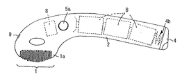
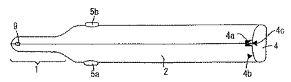
図1は実施例品の体毛処理具の斜視図、図2は左側面図、図3は平面図、図4は底面図、図5の(a)は正面図、(b)は背面図である。
【0023】
1はくし歯部、2はこれに連設した把手部(柄部、握り部)である。くし歯部1は5mm程度の間隔w(図4)をあけて左右線対称に側面を対向させて並設した左右一対のくし歯板1a・1bの対設構成としてある。
【0024】
そして、その2枚のくし歯板1a・1bの対設間隔w内において、くし歯の基部寄りに位置させて前後方向に通電発熱線としてのニクロムワイヤ(以下、ワイヤと略記する)3を張設してある。このワイヤ3は後述するように左右2枚のくし歯板1a・1b間において、着脱(抜き差し)交換自在のワイヤヒータカートリッジ30(図1)に具備させてある。
【0025】
把手部2は電池ボックスとして中空にして単2電池B(図2)を3本収納し、栓蓋4で閉塞して抜け止めるようにしてある。
【0026】
5a・5bは把手部2の基部側の左右両側に夫々に設けた押し釦スイッチである。把手部2を右手で握った状態において、親指が左側面の押し釦スイッチ5aに対応位置し、人差し指が右側面の押し釦スイッチ5bに対応位置する。
【0027】
くし歯板1a・1b、把手部2、栓蓋4は本例のものはABS樹脂、ポリカーボネート樹脂、デルリン樹脂等のモールド成形品である。
【0028】
体毛処理具本体に対してワイヤヒータカートリッジ30が装着されている状態において、把手部2を握り、押し釦スイッチ5a・5bの一方又は両方を指で押すと、後述する通電回路がオンになり、電池Bからワイヤ3に電流が流されて、ワイヤ3が略全長にわたって瞬時に赤熱状態になる。押し釦スイッチ5a・5bから指を離すと、通電回路がオフになり、ワイヤ3の赤熱がやみ、熱容量が小さいから急速に降温する。
【0029】
而して、くし歯板1a・1bのくし歯で体毛をすき揃えながらワイヤ3部分を体毛の適当長さ部分に接触させながら押し釦スイッチ5a・5bで通電回路をオンにするとワイヤ3の赤熱で該ワイヤ3に接触している体毛部分が簡単に焼け切れる。焼け切れた体毛の毛先は刃物で剪断下場合と異なり尖鋭とならず、丸味のあるものとなる。従って、刃物による場合のような前述のような不具合を生じない。
【0030】
ワイヤ3は左右のくし歯板1a・1bの間に位置していてガードされているので直接肌に触れることはない。
【0031】
(2)ワイヤヒータカートリッジ30
図6の(a)はワイヤヒータカートリッジ(以下、カートリッジと略記する)30の左側面図、(b)は右側面図、(c)は正面図、(d)は背面図、図7は分解斜視図である。
【0032】
カートリッジ30は、
1)体毛処理具本体に対する挿入方向前側の第1の電極板31(第1の金属板)と、
2)挿入方向後側の第2の電極板32(第2の金属板)と、
3)カートリッジ右側の第1のスライドフレーム(ベーススライドフレーム、第1のフレーム)33と、
4)カートリッジ左側の第2のスライドフレーム34(第2のフレーム)と、
5)通電発熱線としてのニクロムワイヤ3
の5部品の組み立て体である。
【0033】
1)第1の電極板31
第1の電極板31は、銅板のプレス打ち抜き部品である。図8の(a)と(b)はこの第1の電極板31の左側面図と正面図である。この第1の電極板31の先端部側に上向き突起部311(第1の通電用電極部)を具備させ、この上向き突起部311にワイヤ端部かしめ止め用の半抜き打ち出し部(長方形打出切曲げ部)312を設けてある。また、この電極板面の前部側と後部側に第1と第2の2つの丸小孔313・314を設けてある。
【0034】
上記の半抜き打ち出し部312と第1と第2の丸小孔313・314はこの電極板31の銅板プレス打ち抜きと同時に形成される。
【0035】
また、この第1の電極板31の右側面は、ワイヤ端部かしめ止め用の半抜き打ち出し部312を設けた先端部側上向き突起部311部分を除いて、絶縁フィルム材315を熱間圧着して貼り付け加工(ラミネート加工)して電気的絶縁面にしてある。絶縁フィルム材315は耐熱性のある例えばポリイミドフィルム材が良い。
【0036】
2)第2の電極板32
第2の電極板32も、銅板のプレス打ち抜き部品である。図8の(c)と(d)はこの第2の電極板32の左側面図と正面図である。この第2の電極板32の後端部側に上向き突起部321(第2の通電用電極部)を具備させ、この上向き突起部321にワイヤ端部かしめ止め用の半抜き打ち出し部322を設けてある。また、この電極板面の略中央部に前後方向に長いバネ板部分嵌入孔323を設けてある。またこのバネ板部分嵌入孔323の下側で、電極板前後方向の略中央部に第1の丸小孔324を設けてある。また更に電極板面の後端部側に第2の丸小孔325を設けてある。
【0037】
上記の半抜き打ち出し部322と、バネ板部分嵌入透孔323と、第1と第2の丸小孔323・324はこの電極板32の銅板プレス打ち抜きと同時に形成される。
【0038】
また、この第2の電極板32の左側面は、ワイヤ端部かしめ止め用の半抜き打ち出し部322を設けた後端部側上向き突起部321部分を除いて、絶縁フィルム材326を熱間圧着して貼り付け加工(ラミネート加工)して電気的絶縁面にしてある。絶縁フィルム材326は第1の電極板31の絶縁フィルム材315と同様に耐熱性のある例えばポリイミドフィルム材が良い。
【0039】
3)第1のスライドフレーム33
第1のスライドフレーム33は、ポリアセタールなどの耐熱性プラスチック成形物であり、横断面略逆L字形の前後方向に長い電気絶縁性部材である。長手に沿う外方張り出し縁部がカートリッジ右側ガイド凸条331となる。
【0040】
このスライドフレーム33の内面側には、カートリッジの体毛処理具本体に対する挿入方向前側から後側にかけて順次に、第1の固定ボス332と、第2の固定ボス333と、ストッパー部334と、バネ板部分(弾性付勢部材)335を配列して具備させてあると共に、バネ板部分335の下側に支点ボス336を具備させてある。またこのスライドフレーム33の長手方向略中央部には切欠き窓穴部337を具備させてある。
【0041】
上記の内面側の各部分332〜337はスライドフレーム本体のプラスチック成形と同時に一体成形される。
【0042】
4)第2のスライドフレーム34
第2のスライドフレーム34は、SPCC(鋼板)等の金属板プレス打ち抜き部品であり、横断面略逆L字形の前後方向に長い部材である。長手に沿う外方張り出し縁部がカートリッジ左側ガイド凸条341となる。
【0043】
このスライドフレーム34には、カートリッジの体毛処理具本体に対する挿入方向前側部から後側部にかけて順次に、第1の丸小孔342、第2の丸小孔343、バネ板部分嵌入透孔344を設けてある。またこのバネ板部分嵌入透孔344の下側に第3の丸小孔345を設けてある。またこのスライドフレーム34の長手方向略中央部には切欠き窓穴部346を具備させてある。
【0044】
上記の各部分342〜346はこのスライドフレーム34の成形と同時成形される。
【0045】
5)通電発熱線3
本例において通電発熱線3は0.15m/mφのニクロムワイヤである。
【0046】
6)カートリッジ30の組み立て
上記1)〜4)の4つの部材31〜34間において、図7のように、第1のスライドフレーム33の第1の固定ボス332と、第1の電極板31の第1の丸小孔313と、第2のスライドフレーム34の第1の丸小孔342とが位置対応する。
【0047】
第1のスライドフレーム33の第2の固定ボス333と、第1の電極板31の第2の丸小孔314と、第2のスライドフレーム34の第2の丸小孔343とが位置対応する。
【0048】
第1のスライドフレーム33のバネ板部335と、第2の電極板32のバネ板部分嵌入透孔323と、第2のスライドフレーム34のバネ板部分嵌入透孔344とが位置対応する。
【0049】
また、第1のスライドフレーム33の支点ボス336と、第2の電極板32の第1の丸小孔323と、第2のスライドフレーム34の第3の丸小孔345とが位置対応する。
【0050】
カートリッジ30としての組み立ては次のような手順▲1▼〜▲5▼でなされる。
【0051】
▲1▼.第1のスライドフレーム33に対して第1の電極板31を、第1のスライドフレーム33側の第1と第2の固定ボス332と333にそれぞれ第1の電極板31側の第1と第2の丸小孔313・314を嵌係合させてセットする。
【0052】
▲2▼.第1のスライドフレーム33に対して第2の電極板32を、第1のスライドフレーム33側のバネ板部分335と支点ボス336にそれぞれ第2の電極板32側のバネ板部分嵌入孔323と第1の丸小孔324を嵌係合させてセットする。
【0053】
この場合、第1のスライドフレーム33側のバネ板部分335はその弾性に抗して下方に撓めて先端部分を第2の電極板32側のバネ板部分嵌入孔323の下向き凸部327に引っ掛けて受止めさせた状態にする(図6、図8)。これにより、第2の電極板32にはバネ板部分335の撓み反力により支点ボス336を中心に、図6の(a)において反時計方向への回動付勢力が常時作用する。
【0054】
すなわち、第1の電極板31は第1のスライドフレーム33に対して第1と第2の2本の固定ボス332と333により固定保持されるのに対して、第2の電極板32は第1のスライドフレーム33に対して1本の支点ボス336により該支点ボス336を中心に揺動自由に保持され、かつ上記のようにバネ板部分335により回動付勢される。
【0055】
第1と第2の電極板31・32は第1のスライドフレーム33においてカートリッジの体毛処理具本体に対する挿入方向前後に隙間を存して非接触に離れて位置している。
【0056】
▲3▼.上記のように第1と第2の電極板31・32をセットした第1のスライドフレーム33に対して第2のスライドフレーム34を、第1のスライドフレーム33側のバネ板部分335、第1と第2の固定ボス332と333、および支点ボス336にそれぞれ第2のスライドフレーム34側のバネ板部分嵌入透孔344、第1と第2と第3の丸小孔342・343・345を嵌係合させてセットする。
【0057】
第1と第2の電極板31・32は第1と第2のスライドフレーム33と34の間に前後に位置して介在する。
【0058】
▲4▼.第2のスライドフレーム34の第1と第2と第3の丸小孔342・343・345から外側に突出している、プラスチック材である第1のスライドフレーム33側の第1と第2の固定ボス332と333、および支点ボス336の頭部を熱工具を用いて熱溶融して潰しカシメることで第2のスライドフレーム34を外れ止めする(角型の突起物(デントボス)を設け超音波溶融(SS)で固定する)。
【0059】
これにより、第1と第2の電極板31・32および第1と第2のスライドフレーム33と34の4つの部品の組み立て体が出来上がる。
【0060】
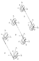
▲5▼.次に、上記の組み立て体において、第2の電極板32をバネ板部分335による回動付勢力に抗して支点ボス336を中心に該第2の電極板32の先端部328が第1のスライドフレーム33側のストッパー334に突き当って受け止められるまで戻し回動してその状態を指で保持し、通電発熱線であるニクロムワイヤ3の先端部と後端部をそれぞれ、第1の電極板31の先端部側上向き突起部311に設けてあるワイヤ端部かしめ止め用の半抜き打ち出し部312の切断ギャップと、第2の電極板32の後端部側上向き突起部321に設けてあるワイヤ端部かしめ止め用の半抜き打ち出し部322の切断ギャップとに挟み込ませる(図9の(a)→(b))。
【0061】
次いで、上記の半抜き打ち出し部312と322をそれぞれプレスでプッシュバックする(図9の(c))。これにより、ニクロムワイヤ3の先端部と後端部がそれぞれプッシュバックされた半抜き打ち出し部312と322に食い込んで第1と第2の電極板31と32の先端部側上向き突起部321と後端部側上向き突起部321とに固定される。
【0062】
この固定されたニクロムワイヤ3は、バネ板部分335の撓み反力による第2の電極板32の支点ボス336を中心とする、図6の(a)において反時計方向への回動付勢力により、第1と第2の電極板31と32の先端部側上向き突起部321と後端部側上向き突起部321との間において常時緊張した状態に保たれる。
【0063】
ここで、上記の通電発熱線であるニクロムワイヤ3の先端部と後端部の、第1と第2の電極板31と32の先端部側上向き突起部321と後端部側上向き突起部321に対する半抜き打ち出し部312と322のプレスプッシュバックによる固定は、第1と第2の電極板31と32の材質をニクロムワイヤ3よりも硬くない材質にすることによりニクロムワイヤ3の先端部と後端部がそれぞれプレスプッシュバックされた半抜き打ち出し部312と322に喰い込み状態になることで強固になされる。
【0064】
本実施例では通電発熱線であるニクロムワイヤ3の硬さ約200(Hv)に対して、第1と第2の電極板31と32として硬さ約80(Hv)以下の純銅板(99%)あるいは焼きナマシ銅板を用いて上記のニクロムワイヤ3の強固な固定処理を問題なくすることができた。なお、上記の硬さの関係が逆の場合には半抜き打ち出し部312と322をプレスプッシュバックしたときニクロムワイヤ3が剪断されたり、確実・強固な固定処理がなされない。
【0065】
即ち、従来品のように、第1と第2の通電用電極部間に対するニクロムワイヤの張り渡しを、ニクロムワイヤの両端部をそれぞれ第1と第2の通電用電極部に対して数回巻き付けて且つ釣り糸のように縛ることで係止しさせて行なっている場合に比べて、作業の手間が格段に短縮化され、且つニクロムワイヤ両端部の固定処理の信頼性が向上した。
【0066】
また、上記のカートリッジ30の組み立て体において、第1と第2のスライドフレーム33と34のうちの一方の第2のスライドフレーム34は金属製にしてあるからカートリッジ全体としての必要強度を確保することができる。
【0067】
また、第2の電極板32の第2のスライドフレーム34との対向面を絶縁フルム材326でラミネート加工して絶縁面にしてあるので、金属製の第2のスライドフレーム34を介して第1と第2の電極板31と32とが電気的にショートすることが防止されている。
【0068】
(3)カートリッジ30の着脱(抜き差し)操作
体毛処理具本体のくし歯部1の左右の各くし歯板1a・1bの背骨板部の内面側には前後方向に、前記カートリッジ30の第1と第2のスライドフレーム33と34の各外向きガイド凸条331と341がスライド係合するガイド凹条11・11(図1、図6、図11)を具備させてある。
【0069】
ヒータカートリッジ30は第1の電極板31側を先にしてくし歯部1の先端側から左右の各くし歯板1a・1bの間に差し入れ(図1、図11の(a)図)、左右のガイド凸条11・11を左右の各くし歯板1a・1bの内面側のガイド凹条11a・11bに合致係合させてスライドさせながら十分に押し込む。
【0070】
十分に押し込むと、くし歯部1の左右の各くし歯板1a・1bの背骨板部の内面側に夫々配設した左右のばね弾性を有する給電用コンタクト6a・6b(図7、図11の(a)、図12)の先端部が夫々、ヒータカートリッジ30の第2のスライドフレーム34の切欠き窓穴346と第1のスライドフレーム33の切欠き窓穴337に対応位置する。
【0071】
そして、左側の給電用コンタクト6aの先端部は第1の電極板31の絶縁フィルム材315をラミネート加工した絶縁面側とは反対面側の導電面に対して電気的に接触した状態になる。また、右側の給電用コンタクト6bの先端部は第2の電極板32の絶縁フィルム材326をラミネート加工した絶縁面側とは反対面側の導電面に対して電気的に接触した状態になる。
【0072】
図11の(b)のようにカートリッジ30がくし歯部1に対して装着され状態において、通電発熱線としてのニクロムワイヤ3は2枚のくし歯板1a・1bの対設間隔w(図4)内にくし歯の基部寄りに前後方向に張った状態で位置する。
【0073】
ニクロムワイヤ3が断線したときは、くし歯部1と把手部2の連設部に軸10aを中心に回動自由に設けたレバー10(図1、図4、図11)を図11の2点鏡線示のように指先で反時計方向に回動操作すると、装着されているカートリッジ30の先端側がレバー10によって押圧されることで第2の電極板32の後端側のつまみ部329がくし歯部1の先端側から外方へ突出する。
【0074】
そこでその外方に突出したつまみ部329を指でつまんで、あるいはこのつまみ部329に位置させて設けてある第2の電極板32の第2の丸小孔325に引き出し用補助具のフック部を引っ掛けてカートリッジ30を装着時とは逆方向に引いて左右のくし歯板1a・1bの間からカートリッジを抜き外して新しいヒータカートリッジ30と差し替えて使用する。
【0075】
このように通電発熱線(ニクロム細線)3は着脱カートリッジ式とすることで経済性がよくなる。
【0076】
また、ニクロムワイヤ緊張機構をカートリッジ側だけに具備させ、体毛処理具本体側には無しにしてあるから、体毛処理具構成が簡素化されて、製品の製造・組み立て工数を減らし、低コスト化等を図ることができる。
【0077】
(4)通電系
体毛処理具本体に対するヒータカートリッジ30の装着状態において、把手部2を握り、スイッチ5a又は5b、もしくは両方を押すと、通電回路8(図12)がオンになり、電源電池Bの電流が給電用コンタクト6a→第1の電極板31→ニクロムワイヤ3→第2の電極板32の経路で流れる。
【0078】
これによりニクロムワイヤ3が略全長にわたって瞬時に赤熱状態になる。スイッチ5a又は/及び5bの押圧を解除すると回路8が開成して通電が断たれ、ニクロムワイヤ3は赤熱がやみ、熱容量が小さいから急速に降温する。
【0079】
第1の電極板31の少なくとも給電用コンタクト6aが対応する導電面部分、および第2の電極板32の少なくとも給電用コンタクト6bが対応する導電面部分は必要に応じて金メッキや耐蝕性のあるニッケルメッキ等することもできる。
【0080】
ニクロムワイヤ3は通電による発熱で線膨張して延びを生じるが、その延びは、バネ板部分335の撓み反力による第2の電極板32の支点ボス336を中心とする、図6の(a)において反時計方向への回動移動により吸収されるので、ニクロムワイヤ3は常に緊張状態が維持される。
【0081】
従って、ニクロムワイヤ3の延びたるみでニクロムワイヤ3が左右のくし歯板1a・1bの内面に過接近状態となったり、或いは直接接触したりしてくし歯板1a・1bを熱損するようなことが防止される。
【0082】
ニクロムワイヤ3に対する通電が断たれると、ニクロムワイヤ3は冷えるに伴ない線収縮し、その収縮力で第2の電極板32がバネ板部分335の撓み反力に抗して支点ボス336を中心に戻り回動する。即ち、ニクロムワイヤ3は通電発熱時も非通電時も常にたるみなく緊張した状態が維持される。
【0083】
また本実施例品はスイッチ5a又は/及び5bを押し続けてもスイッチ−オンから所定のタイマ時間(例えば30〜60秒)経過した後は自動的にニクロムワイヤ3に対する通電が断たれるように、通電回路8にタイマ機能を具備させてある。これによりニクロムワイヤ3に通電がされ続けることによる過熱等を防止でき、安全である。タイマ機能はスイッチ5a又は5bが押される毎にリセットされる。タイマが働いて通電オフとなった後はスイッチ5a又は/及び5bを押し直すことでニクロム細線に対する通電が再び開始される。
【0084】
9(図1〜図3、図5、図11、図12)はくし歯部1の先端側に設けた発光ダイオード等の通電パイロットランプ(LED、緑色ランプと、赤色ランプ)である。このランプ9は通電回路8で制御され、スイッチ5a又は/及び5bが押されているときは緑色ランプが点灯して通電中を表示する。電池Bが消耗して交換しなければならない状態時期になると、スイッチ5a又は/及び5bを押したとき赤色ランプが点滅点灯してその旨を表示する。
【0085】
非使用時は把手部2の電池ボックスの栓蓋4を図4においてマーク4aと4cが一致している状態から反時計回りにマーク4cがマーク4bに一致するまで略45°回動すると、栓蓋4に連動するスイッチ12(図12)が開いて電池回路が開成される。この状態においてはスイッチ5a又は/及び5bが押されてもニクロムワイヤ3には通電されず安全である。この状態から栓蓋4を逆に時計方向へ約45°戻し回動してマーク4aと4cを一致状態にすると、スイッチ12が閉じて電池回路が開成される。
【0086】
栓蓋4は第2図のマーク4aと4cが一致している状態から反時計方向に約90°回動すると把手部2から外れて電池Bの出し入れができる。
【0087】
電源電池Sを把手部2に収納することでコードレスになり、扱い易い。
【0088】
もっとも、把手部2の後端部等に受電用のコンセントを具備させ、このコンセントに対して抜き差し自在のブラグを差し込んで体毛処理具とは別体の電池ホルダからコードを介して給電する構成とすることもでき、この場合は体毛処理具の重量が軽くなり、扱い易い。
【0089】
体毛処理具と、これとは別体の電池ホルダとをコンセント・プラグなしに直接的に電気コードで連絡した構成にしてもよい。
【0090】
商用電源を利用し、これと体毛処理具とを電圧降下器を介してコード接続して通電発熱線に通電する構成にすることもできる。
【0091】
【発明の効果】
以上本発明によれば、従来品の体毛処理具における前述のような問題点を改善して、第1と第2の通電用電極部間に対する通電発熱線の張り渡し係止作業等を合理化するとともに、通電発熱線係止の確実性・信頼性を向上させること、製品構造を簡素化して、製品の製造・組み立て工数を減らし、低コスト化等を図ることが出来る。
【図面の簡単な説明】
【図1】実施例品の体毛処理具の斜視図
【図2】左側面図
【図3】平面図
【図4】底面図
【図5】(a)は正面図、(b)は背面図
【図6】(a)はワイヤヒータカートリッジの左側面図、(b)は右側面図、(c)は正面図、(d)は背面図
【図7】ワイヤヒータカートリッジの分解斜視図
【図8】(a)と(b)は第1の電極板の左側面図と正面図、(c)と(d)はこの第2の電極板の左側面図と正面図
【図9】第1のスライドフレームにセットした第1の電極板部分の斜視図
【図10】ニクロムワイヤ両端部の第1と第2の通電電極部に対する固定処理要領を示す図
【図11】体毛処理具本体に対するワイヤヒータカートリッジの装着要領図
【図12】通電回路図
【符号の説明】
1・・くし歯部、2・・把手部、30・・ワイヤヒータカートリッジ、3・・ニクロムワイヤ、31・・第1の電極板、32・・第2の電極板、33・・第1のスライドフレーム、34・・第2のスライドフレーム、311・・第1の通電電極部、312・・打出切曲げ部、321・・第2の通電電極部、322・・打出切曲げ部、335・・弾性付勢部材(バネ板部分)[0001]
TECHNICAL FIELD OF THE INVENTION
The present invention relates to a body hair treatment tool used for processing unwanted hair such as bikini lines, armpits, legs and arms, and hair conditioning.
[0002]
[Prior art]
For example, if blades such as scissors or a razor are used to treat waste hair such as before wearing a high-leg swimsuit or leotard, the trimmed hair tips are sharp due to shearing by the blades, and the sharp hair tips easily pierce the fabric. Sometimes they pass through and peek outside, or they are touching.
[0003]
Therefore, the present applicant has devised and commercialized a heat treatment device that burns the body hair with an energized heating wire as a hair treatment device capable of trimming the body hair with a rounded hair tip. 1-9).
[0004]
This is because two opposing comb tooth plate portions are arranged side by side with an interval of about 5 to 10 mm facing each other, and a comb tooth plate portion provided between the two opposing comb tooth plate portions. It has a basic structure of an energizing heating wire, specifically a nichrome wire, which comes into contact with the body hair combed into the comb and is energized and burns off the contact hair by heating.
[0005]
Body hair easily burns off when it comes in contact with red-hot nichrome wire. The tip of the burnt body hair does not become sharp, unlike the case where it is sheared with a blade, and has a rounded shape.
[0006]
It is also effective when used as a hairdressing instrument for hairdressing and beauty surgery. In other words, a nichrome wire portion is brought into contact with a hair tip portion that has been hair-slided, and the hair tip is processed into a burned-out state, whereby the hair tip can be rounded, delicately curved or shrunk to give a unique texture to the hair hair.
[0007]
In consideration of the easiness of handling and repairing when the nichrome wire is broken, the nichrome wire can be easily inserted into and removed from the body hair treatment tool body and can be replaced between the first and second energizing electrode portions of the wire heater cartridge. It is stretched and provided so that when the nichrome wire is broken, it can be replaced with a new cartridge.
[0008]
In a state where the cartridge is mounted on the hair treatment device main body, the electric contact member on the cartridge side and the electric contact member on the body hair treatment device main body are in contact with each other, and power is supplied from the body hair treatment device main body to the nichrome wire on the cartridge side. It becomes possible.
[0009]
Further, an elastic biasing member such as a leaf spring is provided on the body hair processing tool main body side, and in a state where the cartridge is mounted on the body hair processing tool main body, the tension is always applied to the nichrome wire by the elastic biasing member, It is designed to absorb the slackening caused by the thermal expansion of the nichrome wire during heat generation.
[Patent Document 1]
Japanese Utility Model Publication No. 4-037521
[Patent Document 2]
Japanese Utility Model Publication No. 6-014649
[Patent Document 3]
Registered Utility Model No. 2006125
[Patent Document 4]
Patent No. 3109455
[Patent Document 5]
Patent No. 3147816
[Patent Document 6]
Design Registration No. 857135
[Patent Document 7]
JP-A-8-289814
[Patent Document 8]
JP-A-9-248212
[Patent Document 9]
JP 2000-83723 A
[0010]
[Problems to be solved by the invention]
In the conventional product, the first and second current-carrying electrode portions on which a nichrome wire as a current-carrying heat wire is stretched are formed by using an insulating plate as a base material and providing a conductive layer on the surface thereof. The nichrome wire is stretched between the first and second current-carrying electrode portions by winding the both ends of the nichrome wire several times around the first and second current-carrying electrode portions and tying it like a fishing line. It is done by locking. However, this work is time-consuming and one of the points to be improved.
[0011]
Further, as described above, the body hair treatment tool main body is provided with an elastic urging member such as a leaf spring, and in the state where the cartridge is mounted on the body hair treatment tool main body, the tension is constantly applied to the nichrome wire by the elastic urging member. In this way, the slackening due to the thermal expansion of the nichrome wire during heat generation is absorbed, but the mechanism for tensioning the nichrome wire between the body hair treatment tool main body side and the cartridge side complicates the body hair treatment tool configuration. In addition, the number of man-hours for manufacturing and assembling products is increased, which affects costs and the like, and this is one of the points to be improved.
[0012]
The present invention solves the above-described problems in the conventional hair treatment device, rationalizes the work of bridging the heat-generating wire between the first and second current-carrying electrode portions, and reduces the current. An object of the present invention is to improve the reliability and reliability of the heating wire locking, simplify the product structure, reduce the number of manufacturing and assembling steps of the product, and reduce the cost.
[0013]
[Means for Solving the Problems]
The present invention is a body hair treatment tool and a wire heater cartridge having the following configurations.
[0014]
(1) Two comb tooth plate portions arranged side by side with a space between them, and first and second current-carrying electrode portions having both ends between the two opposing comb tooth plate portions, respectively. A hair treatment device having an energizing heating wire which is disposed so as to be engaged with and stretched over, and which comes into contact with body hair combed into the comb teeth of the comb tooth plate portion and is energized to glow red to burn off the contact body hair. ,
The first and second current-carrying electrode portions are metal plates that are not harder than the current-carrying heat-generating wires. Characterized in that the end of the current-carrying heating wire is locked to the current-carrying electrode by being pushed back by a press.
[0015]
(2) Two comb tooth plate portions arranged side by side with a space between them, and first and second current-carrying electrode portions having both ends between the two opposing comb tooth plate portions, respectively. It has an energizing heat generating wire which is arranged so as to be engaged with and stretched over, and which comes into contact with body hair combed into the comb teeth of the comb tooth plate portion and is energized to glow red to burn off the contact hair. The wire is a hair treatment tool provided in a wire heater cartridge detachably attached to the body hair treatment tool main body, including the first and second energizing electrode portions,
The first and second current-carrying electrode portions are metal plates that are not harder than the current-carrying heat-generating wires. Characterized in that the end of the current-carrying heating wire is locked to the current-carrying electrode by being pushed back by a press.
[0016]
(3) Two comb-tooth plate portions juxtaposed with their side surfaces facing each other at intervals and first and second current-carrying electrode portions at both ends between the two opposing comb-tooth plate portions It has an energizing heat generating wire which is arranged so as to be engaged with and stretched over, and which comes into contact with body hair combed into the comb teeth of the comb tooth plate portion and is energized to glow red to burn off the contact hair. The wire is a hair treatment tool provided in a wire heater cartridge that is detachable from the body hair treatment tool main body including the first and second current-carrying electrode portions,
The first and second current-carrying electrode portions are metal plates that are not harder than the current-carrying heat-generating wires. Is pushed back by the press so that the end of the current-carrying heating wire is locked to the current-carrying electrode portion, and one of the first and second current-carrying electrode portions is configured to be movable. A hair-removing member having an elastic urging member for moving and urging the wire in a direction away from the other to keep the energized heating wire in a tensioned state, and having the elastic urging member provided on the wire heater cartridge side. Utensils.
[0017]
(4) The wire heater cartridge comprises:
1) a first metal plate having a first current-carrying electrode portion;
2) a second metal plate provided with a second current-carrying electrode portion;
3) a first frame made of a plastic material that fixes and holds the first metal plate, and separates from the first metal plate to rotatably hold the second metal plate;
4) a second metal frame, which is disposed on the opposite side of the first frame with the first metal plate and the second metal plate therebetween and is coupled to the first frame;
5) an energizing heat generation wire which is disposed so that both ends thereof are engaged and stretched over the first energizing electrode portion of the first metal plate and the second energizing electrode portion of the second metal plate, respectively. ,
An insulating layer is formed on a surface of the second metal plate facing the second frame, and the second metal plate is turned on the first frame by rotating the second metal plate. The body hair treatment device according to (3), further including an elastic urging member that moves and urges the portion in a direction away from the first energizing electrode portion to keep the energized heating wire in a tensioned state.
[0018]
(5) Two energizing heating wires having both ends locked and stretched over the first and second energizing electrode portions and arranged side by side with a space therebetween with a gap therebetween It is detachably attached to the body hair treatment tool main body having the comb tooth plate portion, and when it is attached, the heating wire is positioned between the two opposing comb tooth plate portions and inserted into the comb teeth of the comb tooth plate portion. A wire heater cartridge that burns out the contact hair by red heating by being energized while being in contact with the worn hair;
The first and second current-carrying electrode portions are metal plates that are not harder than the current-carrying heat-generating wires. A wire heater cartridge characterized in that the end of the current-carrying heating wire is locked to the current-carrying electrode by being pushed back by a press.
[0019]
(6) Two heat-generating wires, which are arranged so that both ends are locked and stretched over the first and second current-carrying electrode portions, and are arranged side by side with a space therebetween with a gap therebetween It is detachably attached to the body hair treatment tool main body having the comb tooth plate portion, and when it is attached, the heating wire is located between the two opposing comb tooth plate portions and inserted into the comb teeth of the comb tooth plate portion. A wire heater cartridge that burns out the contact hair by red heating by being energized while being in contact with the worn hair;
The first and second current-carrying electrode portions are metal plates that are not harder than the current-carrying heat-generating wires. Is pushed back by the press so that the end of the current-carrying heating wire is locked to the current-carrying electrode portion, and one of the first and second current-carrying electrode portions is configured to be movable. A wire heater cartridge having an elastic biasing member for biasing the electric heating wire in a direction away from the other to keep the energized heating wire in a tensioned state.
[0020]
(7) The wire heater cartridge comprises:
1) a first metal plate having a first current-carrying electrode portion;
2) a second metal plate provided with a second current-carrying electrode portion;
3) a first frame made of a plastic material that fixes and holds the first metal plate, and separates from the first metal plate to rotatably hold the second metal plate;
4) a second metal frame, which is disposed on the opposite side of the first frame with the first metal plate and the second metal plate therebetween and is coupled to the first frame;
5) an energizing heat generation wire which is disposed so that both ends thereof are engaged and stretched over the first energizing electrode portion of the first metal plate and the second energizing electrode portion of the second metal plate, respectively. ,
An insulating layer is formed on a surface of the second metal plate facing the second frame, and the second metal plate is turned on the first frame by rotating the second metal plate. 7. The wire heater cartridge according to claim 6, further comprising an elastic biasing member for moving and biasing the portion in a direction away from the first energizing electrode portion to keep the energizing heating wire in a tensioned state.
[0021]
BEST MODE FOR CARRYING OUT THE INVENTION
Hereinafter, a specific description will be given based on an example product shown in the drawings.
[0022]
(1) Overall configuration of body hair treatment tool
1 is a perspective view of a hair treatment device of an example product, FIG. 2 is a left side view, FIG. 3 is a plan view, FIG. 4 is a bottom view, FIG. 5 (a) is a front view, and (b) is a rear view. is there.
[0023]
1 is a comb portion, and 2 is a handle portion (handle portion, grip portion) connected to the comb portion. The
[0024]
Then, a nichrome wire (hereinafter abbreviated as a wire) 3 as an energizing heating wire is stretched in the front-rear direction within the space w between the two
[0025]
The
[0026]
[0027]
In this embodiment, the
[0028]
In a state where the
[0029]
When the energizing circuit is turned on by the
[0030]
Since the
[0031]
(2)
6 (a) is a left side view of a wire heater cartridge (hereinafter abbreviated as a cartridge) 30, (b) is a right side view, (c) is a front view, (d) is a rear view, and FIG. 7 is an exploded view. It is a perspective view.
[0032]
The
1) a first electrode plate 31 (first metal plate) on the front side in the insertion direction with respect to the body hair treatment tool main body;
2) a second electrode plate 32 (second metal plate) on the rear side in the insertion direction;
3) a first slide frame (base slide frame, first frame) 33 on the right side of the cartridge;
4) a second slide frame 34 (second frame) on the left side of the cartridge;
5)
It is an assembly of five parts.
[0033]
1)
The
[0034]
The above-described half punched-out
[0035]
Further, the right side surface of the
[0036]
2)
The
[0037]
The above half punched-out
[0038]
The left side surface of the
[0039]
3)
The
[0040]
On the inner surface side of the
[0041]
Each
[0042]
4)
The
[0043]
In the
[0044]
Each of the
[0045]
5)
In this example, the
[0046]
6) Assembly of
As shown in FIG. 7, between the four
[0047]
Second fixed
[0048]
[0049]
Also, the
[0050]
Assembly as the
[0051]
▲ 1 ▼. The
[0052]
▲ 2 ▼. The
[0053]
In this case, the
[0054]
That is, the
[0055]
The first and
[0056]
(3). The
[0057]
The first and
[0058]
▲ 4 ▼. First, second, and third round holes 34 of the
[0059]
Thus, an assembly of four parts, that is, the first and
[0060]
▲ 5 ▼. Next, in the above assembly, the
[0061]
Next, the half-punching-out
[0062]
The fixed
[0063]
Here, the upwardly projecting
[0064]
In this embodiment, the first and
[0065]
That is, the nichrome wire is stretched between the first and second energizing electrode portions several times around the first and second energizing electrode portions, respectively, as in the conventional product. As compared with the case where the fishing rod is tied and locked like a fishing line, the labor of the work is remarkably reduced, and the reliability of the fixing process of the both ends of the nichrome wire is improved.
[0066]
In the assembly of the
[0067]
Also, since the surface of the
[0068]
(3) Attaching / detaching (removing and inserting) the
The outer surfaces of the first and second slide frames 33 and 34 of the
[0069]
The
[0070]
When pressed sufficiently, the
[0071]
The tip of the left
[0072]
When the
[0073]
When the
[0074]
Therefore, the
[0075]
As described above, the electric heating wire (the thin nichrome wire) 3 is made of a detachable cartridge type, so that the economy is improved.
[0076]
In addition, since the nichrome wire tensioning mechanism is provided only on the cartridge side and not on the body hair treatment tool main body side, the structure of the body hair treatment tool is simplified, the man-hours for manufacturing and assembling the product are reduced, and the cost is reduced. Can be achieved.
[0077]
(4) Energizing system
In the state where the
[0078]
As a result, the
[0079]
At least the conductive surface portion of the
[0080]
The
[0081]
Accordingly, the extension of the
[0082]
When the current supply to the
[0083]
In this embodiment, even if the
[0084]
Reference numeral 9 (FIGS. 1 to 3, 5, 11, and 12) denotes a current-carrying pilot lamp (an LED, a green lamp, and a red lamp) such as a light-emitting diode provided on the tip end side of the
[0085]
When not in use, the lid 4 of the battery box of the
[0086]
When the stopper lid 4 is rotated counterclockwise by about 90 ° from the state where the
[0087]
Storing the power supply battery S in the
[0088]
However, a configuration is provided in which a power receiving outlet is provided at the rear end of the
[0089]
A configuration may be employed in which the body hair treatment tool and a separate battery holder are connected directly by an electric cord without an outlet or plug.
[0090]
It is also possible to use a commercial power supply, connect it to the body hair treatment tool via a voltage dropper, and connect the cord to the power-generating heating wire.
[0091]
【The invention's effect】
According to the present invention as described above, the above-mentioned problems in the conventional hair treatment device are improved, and the work of bridging and engaging the energized heating wire between the first and second energizing electrode portions is rationalized. At the same time, it is possible to improve the reliability and reliability of the energized heating wire locking, simplify the product structure, reduce the number of manufacturing and assembling steps of the product, and reduce the cost.
[Brief description of the drawings]
FIG. 1 is a perspective view of a hair treatment tool of an example product.
FIG. 2 is a left side view.
FIG. 3 is a plan view
FIG. 4 is a bottom view
5A is a front view, and FIG. 5B is a rear view.
6A is a left side view of the wire heater cartridge, FIG. 6B is a right side view, FIG. 6C is a front view, and FIG. 6D is a rear view.
FIG. 7 is an exploded perspective view of the wire heater cartridge.
8A and 8B are a left side view and a front view of a first electrode plate, and FIGS. 8C and 8D are a left side view and a front view of the second electrode plate.
FIG. 9 is a perspective view of a first electrode plate portion set on a first slide frame.
FIG. 10 is a diagram showing a procedure for fixing both ends of a nichrome wire to first and second current-carrying electrode portions.
FIG. 11 is a view showing how to attach a wire heater cartridge to the body hair treatment tool main body.
FIG. 12 is an energization circuit diagram.
[Explanation of symbols]
1 comb tooth part, 2 handle part, 30 wire heater cartridge, 3 nichrome wire, 31 first electrode plate, 32 second electrode plate, 33 first Slide frame, 34 second slide frame, 31 1 ..First conducting electrode portion, 31 2 ..Punching and bending portions, 32 1 ..Second energized electrode portions, 32 2 ..Punching and bending parts, 33 5 ..Elastic biasing members (spring plate portions)
Claims (7)
第1と第2の通電用電極部は通電発熱線よりも硬くない金属板であり、それぞれに設けられた打出切曲げ部の切断ギャップに通電発熱線の端部が通されて打出切曲げ部がプレスでプッシュバックされていることで通電発熱線端部が通電用電極部に係止されていることを特徴とする体毛処理具。Two comb tooth plate portions arranged side by side with a space between them, and both end portions between the two opposing comb tooth plate portions are respectively locked to the first and second current supply electrode portions. A hair treatment device having an energizing heating wire that is arranged and stretched, and is in contact with body hair combed into the comb teeth of the comb tooth plate portion and is energized and glows red to burn off the contact body hair.
The first and second current-carrying electrode portions are metal plates that are not harder than the current-carrying heat-generating wires. Characterized in that the end of the current-carrying heating wire is locked to the current-carrying electrode by being pushed back by a press.
第1と第2の通電用電極部は通電発熱線よりも硬くない金属板であり、それぞれに設けられた打出切曲げ部の切断ギャップに通電発熱線の端部が通されて打出切曲げ部がプレスでプッシュバックされていることで通電発熱線端部が通電用電極部に係止されていることを特徴とする体毛処理具。Two comb tooth plate portions arranged side by side with a space between them, and both end portions between the two opposing comb tooth plate portions are respectively locked to the first and second current supply electrode portions. A heating wire that contacts the body hair combed into the comb teeth of the comb tooth plate portion and is energized and glows red to burn off the contact body hair. A hair treatment tool provided in a wire heater cartridge detachable from the body hair treatment tool main body including the first and second energizing electrode portions,
The first and second current-carrying electrode portions are metal plates that are not harder than the current-carrying heat-generating wires. Characterized in that the end of the current-carrying heating wire is locked to the current-carrying electrode by being pushed back by a press.
第1と第2の通電用電極部は通電発熱線よりも硬くない金属板であり、それぞれに設けられた打出切曲げ部の切断ギャップに通電発熱線の端部が通されて打出切曲げ部がプレスでプッシュバックされていることで通電発熱線端部が通電用電極部に係止されており、第1と第2の通電用電極部の一方は可動に構成され、その通電用電極部を他方から離間する方向に移動付勢して通電発熱線を緊張状態に保つ弾性付勢部材を有し、該弾性付勢部材をワイヤヒータカートリッジ側に具備させていることを特徴とする体毛処理具。Two comb tooth plate portions arranged side by side with a space between them, and both end portions between the two opposing comb tooth plate portions are respectively locked to the first and second current supply electrode portions. A heating wire that contacts the body hair combed into the comb teeth of the comb tooth plate portion and is energized and glows red to burn off the contact hair. A hair treatment tool provided in a wire heater cartridge that is detachable from the body hair treatment tool main body, including the first and second energizing electrode portions,
The first and second current-carrying electrode portions are metal plates that are not harder than the current-carrying heat-generating wires. Is pushed back by the press so that the end of the current-carrying heating wire is locked to the current-carrying electrode portion, and one of the first and second current-carrying electrode portions is configured to be movable. A hair-removing member having an elastic urging member for moving and urging the wire in a direction away from the other to keep the energized heating wire in a tensioned state, and having the elastic urging member provided on the wire heater cartridge side. Utensils.
1)第1の通電用電極部を具備させた第1の金属板と、
2)第2の通電用電極部を具備させた第2の金属板と、
3)第1の金属板を固定して保持し、該第1の金属板から離間させて第2の金属板を回動可能に保持するプラスチック材製の第1のフレームと、
4)第1の金属板と第2の金属板を中にして第1のフレーム側とは反対側に配設され、第1のフレームと結合される、金属材製の第2のフレームと、
5)第1の金属板の第1の通電用電極部と第2の金属板の第2の通電用電極部とに両端部をそれぞれ係止して張り渡して配設された通電発熱線と、
を有し、第2の金属板の第2のフレームとの対向面には絶縁層が形成され、第1のフレームに、第2の金属板を回動付勢して第2の通電用電極部を第1の通電用電極部から離間する方向に移動付勢して通電発熱線を緊張状態に保つ弾性付勢部材を具備させたことを特徴とする請求項3に記載の体毛処理具。The wire heater cartridge,
1) a first metal plate having a first current-carrying electrode portion;
2) a second metal plate provided with a second current-carrying electrode portion;
3) a first frame made of a plastic material that fixes and holds the first metal plate, and separates from the first metal plate to rotatably hold the second metal plate;
4) a second metal frame, which is disposed on the opposite side of the first frame with the first metal plate and the second metal plate therebetween and is coupled to the first frame;
5) an energizing heat generation wire which is disposed so that both ends thereof are engaged and stretched over the first energizing electrode portion of the first metal plate and the second energizing electrode portion of the second metal plate, respectively. ,
An insulating layer is formed on a surface of the second metal plate facing the second frame, and the second metal plate is turned on the first frame by rotating the second metal plate. The body hair treatment tool according to claim 3, further comprising an elastic urging member that moves and urges the portion in a direction away from the first energizing electrode portion to keep the energized heating wire in a tensioned state.
第1と第2の通電用電極部は通電発熱線よりも硬くない金属板であり、それぞれに設けられた打出切曲げ部の切断ギャップに通電発熱線の端部が通されて打出切曲げ部がプレスでプッシュバックされていることで通電発熱線端部が通電用電極部に係止されていることを特徴とするワイヤヒータカートリッジ。Two comb tooth plates having energizing heat generating wires disposed at both ends of the first and second energizing electrode portions so as to be engaged and stretched, and spaced side by side so as to face each other It is detachable from the body hair treatment tool main body having a part, and when it is attached, the heating wire is located between the two opposing comb tooth plates, and the hair is combed into the comb teeth of the comb tooth plate. In a wire heater cartridge which burns out the contact body hairs by being heated by contact and being energized,
The first and second current-carrying electrode portions are metal plates that are not harder than the current-carrying heat-generating wires. A wire heater cartridge characterized in that the end of the current-carrying heating wire is locked to the current-carrying electrode by being pushed back by a press.
第1と第2の通電用電極部は通電発熱線よりも硬くない金属板であり、それぞれに設けられた打出切曲げ部の切断ギャップに通電発熱線の端部が通されて打出切曲げ部がプレスでプッシュバックされていることで通電発熱線端部が通電用電極部に係止されており、第1と第2の通電用電極部の一方は可動に構成され、その通電用電極部を他方から離間する方向に移動付勢して通電発熱線を緊張状態に保つ弾性付勢部材を有していることを特徴とするワイヤヒータカートリッジ。Two comb tooth plates having energizing heat generating wires disposed at both ends of the first and second energizing electrode portions so as to be engaged and stretched, and spaced side by side so as to face each other It is detachable from the body hair treatment tool main body having a part, and when it is attached, the heating wire is located between the two opposing comb tooth plates, and the hair is combed into the comb teeth of the comb tooth plate. In a wire heater cartridge which burns out the contact body hairs by being heated by contact and being energized,
The first and second current-carrying electrode portions are metal plates that are not harder than the current-carrying heat-generating wires. Is pushed back by the press so that the end of the current-carrying heating wire is locked to the current-carrying electrode portion, and one of the first and second current-carrying electrode portions is configured to be movable. A wire heater cartridge having an elastic biasing member for biasing the electric heating wire in a direction away from the other to keep the energized heating wire in a tensioned state.
1)第1の通電用電極部を具備させた第1の金属板と、
2)第2の通電用電極部を具備させた第2の金属板と、
3)第1の金属板を固定して保持し、該第1の金属板から離間させて第2の金属板を回動可能に保持するプラスチック材製の第1のフレームと、
4)第1の金属板と第2の金属板を中にして第1のフレーム側とは反対側に配設され、第1のフレームと結合される、金属材製の第2のフレームと、
5)第1の金属板の第1の通電用電極部と第2の金属板の第2の通電用電極部とに両端部をそれぞれ係止して張り渡して配設された通電発熱線と、
を有し、第2の金属板の第2のフレームとの対向面には絶縁層が形成され、第1のフレームに、第2の金属板を回動付勢して第2の通電用電極部を第1の通電用電極部から離間する方向に移動付勢して通電発熱線を緊張状態に保つ弾性付勢部材を具備させたことを特徴とする請求項6に記載のワイヤヒータカートリッジ。The wire heater cartridge,
1) a first metal plate having a first current-carrying electrode portion;
2) a second metal plate provided with a second current-carrying electrode portion;
3) a first frame made of a plastic material that fixes and holds the first metal plate, and separates from the first metal plate to rotatably hold the second metal plate;
4) a second metal frame, which is disposed on the opposite side of the first frame with the first metal plate and the second metal plate therebetween and is coupled to the first frame;
5) an energizing heat generation wire which is disposed so that both ends thereof are engaged and stretched over the first energizing electrode portion of the first metal plate and the second energizing electrode portion of the second metal plate, respectively. ,
An insulating layer is formed on a surface of the second metal plate facing the second frame, and the second metal plate is turned on the first frame by rotating the second metal plate. 7. The wire heater cartridge according to claim 6, further comprising an elastic biasing member for moving and biasing the portion in a direction away from the first energizing electrode portion to keep the energizing heating wire in a tensioned state.
Priority Applications (1)
| Application Number | Priority Date | Filing Date | Title |
|---|---|---|---|
| JP2002281115A JP2004113476A (en) | 2002-09-26 | 2002-09-26 | Body hair treatment device and wire heater cartridge |
Applications Claiming Priority (1)
| Application Number | Priority Date | Filing Date | Title |
|---|---|---|---|
| JP2002281115A JP2004113476A (en) | 2002-09-26 | 2002-09-26 | Body hair treatment device and wire heater cartridge |
Publications (1)
| Publication Number | Publication Date |
|---|---|
| JP2004113476A true JP2004113476A (en) | 2004-04-15 |
Family
ID=32275652
Family Applications (1)
| Application Number | Title | Priority Date | Filing Date |
|---|---|---|---|
| JP2002281115A Ceased JP2004113476A (en) | 2002-09-26 | 2002-09-26 | Body hair treatment device and wire heater cartridge |
Country Status (1)
| Country | Link |
|---|---|
| JP (1) | JP2004113476A (en) |
Cited By (3)
| Publication number | Priority date | Publication date | Assignee | Title |
|---|---|---|---|---|
| CN110422402A (en) * | 2019-07-15 | 2019-11-08 | 杭州铭瑞佳机械科技有限公司 | The heating sealing device and its mouth-sealing method of the dedicated middle chartered plane of sanitary towels |
| JP2020073793A (en) * | 2019-10-02 | 2020-05-14 | 株式会社丸和製作所 | Actuator and manufacturing device of actuator |
| US11450495B2 (en) | 2017-11-17 | 2022-09-20 | Maruwa Corporation | Actuator and actuator manufacturing method |
-
2002
- 2002-09-26 JP JP2002281115A patent/JP2004113476A/en not_active Ceased
Cited By (4)
| Publication number | Priority date | Publication date | Assignee | Title |
|---|---|---|---|---|
| US11450495B2 (en) | 2017-11-17 | 2022-09-20 | Maruwa Corporation | Actuator and actuator manufacturing method |
| CN110422402A (en) * | 2019-07-15 | 2019-11-08 | 杭州铭瑞佳机械科技有限公司 | The heating sealing device and its mouth-sealing method of the dedicated middle chartered plane of sanitary towels |
| JP2020073793A (en) * | 2019-10-02 | 2020-05-14 | 株式会社丸和製作所 | Actuator and manufacturing device of actuator |
| JP7114087B2 (en) | 2019-10-02 | 2022-08-08 | 株式会社丸和製作所 | Actuator and actuator manufacturing method |
Similar Documents
| Publication | Publication Date | Title |
|---|---|---|
| EP0888733B1 (en) | Body hair treating implement | |
| US5064993A (en) | Hair treating implement with a heated wire element | |
| US20060027554A1 (en) | Body hair treating implement | |
| KR101457766B1 (en) | Handle assembly and the razor using the same | |
| CA2917281A1 (en) | An electrical hair removal device and control method | |
| WO2012159022A2 (en) | Razor with blade heating system | |
| KR20140042230A (en) | Heating shaving cartridge | |
| US20130263881A1 (en) | Hair straightener | |
| JP2002066172A (en) | Shaver | |
| JP2004113476A (en) | Body hair treatment device and wire heater cartridge | |
| US9399304B2 (en) | Heated razor with power switch on cartridge | |
| KR100915371B1 (en) | Heat cutting type hair remove apparatus | |
| JPH09248212A (en) | Body hair shaver | |
| JPH0614649Y2 (en) | Hair treatment tool | |
| AU757257B2 (en) | Body hair treating implement | |
| JPH0437521Y2 (en) | ||
| CA2470672C (en) | Body hair treating implement | |
| AU735061B2 (en) | Body hair treating implement | |
| JP2000083723A (en) | Body hair processing tool | |
| JP3548053B2 (en) | Eyelash curler | |
| JP3006125U (en) | Hair treatment tool | |
| JP5791457B2 (en) | Hair treatment equipment | |
| JPH0436682B2 (en) | ||
| JPH08289814A (en) | Hair treating tool | |
| JP3017601U (en) | Body hair burner |
Legal Events
| Date | Code | Title | Description |
|---|---|---|---|
| A977 | Report on retrieval |
Free format text: JAPANESE INTERMEDIATE CODE: A971007 Effective date: 20050629 |
|
| A131 | Notification of reasons for refusal |
Free format text: JAPANESE INTERMEDIATE CODE: A131 Effective date: 20060606 |
|
| A521 | Written amendment |
Free format text: JAPANESE INTERMEDIATE CODE: A523 Effective date: 20060724 |
|
| A01 | Written decision to grant a patent or to grant a registration (utility model) |
Free format text: JAPANESE INTERMEDIATE CODE: A01 Effective date: 20061205 |
|
| A045 | Written measure of dismissal of application |
Free format text: JAPANESE INTERMEDIATE CODE: A045 Effective date: 20070424 |