JP2004111148A - Push button switch and mounting structure therefor - Google Patents
Push button switch and mounting structure therefor Download PDFInfo
- Publication number
- JP2004111148A JP2004111148A JP2002270277A JP2002270277A JP2004111148A JP 2004111148 A JP2004111148 A JP 2004111148A JP 2002270277 A JP2002270277 A JP 2002270277A JP 2002270277 A JP2002270277 A JP 2002270277A JP 2004111148 A JP2004111148 A JP 2004111148A
- Authority
- JP
- Japan
- Prior art keywords
- button switch
- conductive
- push button
- reversing spring
- frame
- Prior art date
- Legal status (The legal status is an assumption and is not a legal conclusion. Google has not performed a legal analysis and makes no representation as to the accuracy of the status listed.)
- Pending
Links
Images


Landscapes
- Push-Button Switches (AREA)
- Details Of Cameras Including Film Mechanisms (AREA)
Abstract
Description
【0001】
【発明の属する技術分野】
本発明は、押釦スイッチとその取付構造とに係り、特に、オートフォーカス機能を備えたカメラなどに組み込まれる2段動作スイッチの構成と、カメラなどの電気機器の筐体に対する2段動作スイッチの取付構造とに関する。
【0002】
【従来の技術】
図8に、従来より知られているこの種の押釦スイッチの一例を示す。この図から明らかなように、本例の押釦スイッチは、浅底の箱形状を有するベース101と、当該ベース101の所定の位置に設定された外周固定接点102、中央固定接点103及び共通固定接点104と、前記外周固定接点102と常時電気的に接続され、反転時に前記中央固定接点103と電気的に接続される導電性皿状反転バネ105と、前記共通固定接点104と常時電気的に接続され、動作時に前記導電性皿状反転バネ105と電気的に接続されるリーフバネ106と、当該リーフバネ106に形成された可動舌片107を押圧する樹脂バネフィルム108と、前記ベース101の開口部に被着された防塵用のゴムシート109と、当該ゴムシート109の外面に被着された金属板製のカバー110とから構成されており、前記カバー110の中央部には、外部より前記ゴムシート109を介して前記樹脂バネフィルム108を押圧操作するための操作孔111が開設されている。なお、この種の押釦スイッチとしては、特開2002−124153に開示された2段動作スイッチなどを挙げることができる。
【0003】
本例の押釦スイッチは、非操作時においては、図8に示すように、導電性皿状反転バネ105が上向きに湾曲して外周固定接点102と中央固定接点103とが電気的に切離されている。また、樹脂バネフィルム108も上向きに湾曲していて可動舌片107が非動作状態にあり、外周固定接点102及び中央固定接点103と共通固定接点104とが電気的に切離されている。
【0004】
この押釦スイッチの接点切替は、ゴムシート109の外面中央部に先端部が当接された図示しないキートップを押圧操作することによって行われる。即ち、図示しないキートップが押圧されると、樹脂バネフィルム108の中央部分が下向きに湾曲されてリーフバネ106の可動舌片107が下向きに弾性変形される。そして、可動舌片107と導電性皿状反転バネ105とが接触した段階で外周固定接点102と共通固定接点104とが導通し、第1の接点切替状態になる。また、この状態からさらに図示しないキートップを押圧すると、その押圧力によって導電性皿状反転バネ105が下向きに反転し、導電性皿状反転バネ105とリーフバネ106とを介して外周固定接点102、中央固定接点103及び共通固定接点104が導通し、第2の接点切替状態になる。
【0005】
第1の接点切替状態又は第2の接点切替状態からキートップに加えられていた押圧力を除けば、導電性皿状反転バネ105、リーフバネ106、樹脂バネフィルム108及びゴムシート109の弾性力により、図8に示す非操作状態に自動的に復帰する。
【0006】
【発明が解決しようとする課題】
しかしながら、前記従来例に係る押釦スイッチは、可動舌片107よりも上方に樹脂バネフィルム108とゴムシート109とカバー110とが配置されているので、押釦スイッチの全高Hが大きく、当該押釦スイッチが備えられる電気機器に大きなスイッチ設定スペースを必要とするという不都合がある。
【0007】
また、この種の押釦スイッチは、電気機器の筐体に備えられるキートップの動揺を防止し、押釦スイッチの使用感を良好なものにするため、キートップをゴムシート109の外面に弾接して樹脂バネフィルム108に予圧をかける必要があるが、前記従来例に係る押釦スイッチは、可動舌片107の上方にカバー110を配置し、当該カバー110の中央部に開設された操作孔111を通してキートップの下端部をゴムシート109の外面中央部に当接する構成であるので、電気機器への組み込み時、まず、電気機器に設けられたスイッチ設定スペース内に押釦スイッチを収納して外周固定接点102、中央固定接点103及び共通固定接点104を電気機器に備えられた電気回路と接続し、しかる後に、スイッチ設定スペースの上方よりキートップが弾性保持されたカバー部材を電気機器の筐体を被着し、キートップの下端部をゴムシート109の外面中央部に弾接するか、或いは、電気機器の筐体に予めキートップを弾性保持しておき、当該キートップの下端部側から押釦スイッチを上昇させてキートップの下端部をゴムシート109の外面中央部に弾接し、しかる後に、外周固定接点102、中央固定接点103及び共通固定接点104を電気機器に備えられた電気回路と接続するという方法を採らなくてはならず、電気機器に対する押釦スイッチの組立工程が複雑で、電気機器のレイアウトも制限されるという不都合がある。
【0008】
本発明は、かかる技術的課題を解決するためになされたものであり、その目的とするところは、薄形にして電気機器への取り付けが容易な押釦スイッチを提供すること、及び電気機器に対する押釦スイッチの取り付けを容易化できる押釦スイッチの取付構造を提供することにある。
【0009】
【課題を解決するための手段】
本発明は、前記の課題を解決するため、押釦スイッチに関しては、第1乃至第3の固定接点を有する基体と、前記第1の固定接点と常時電気的に接続され、反転時に前記第2の固定接点と電気的に接続される第1の導電性反転ばねと、前記第3の固定接点と常時電気的に接続され、反転時に前記第1の導電性反転ばねと電気的に接続される第2の導電性反転ばねと、前記基体との間で前記第2の導電性反転ばねを動作可能に保持するフレームとを備え、前記第2の導電性反転ばねの操作部を前記フレームに開設されたキートップ挿通孔内に設定し、かつ前記第2の導電性反転ばねの操作部を前記フレームの上面よりも上方に配置するという構成にした。
【0010】
このように、押釦スイッチを、第1乃至第3の固定接点を有する基体と、第1及び第2の導電性反転ばねと、フレームとから構成すると、従来例に係る押釦スイッチに備えられていたリーフバネを省略できるので、押釦スイッチの薄形化を図ることができる。また、第2の導電性反転ばねの操作部をフレームに開設されたキートップ挿通孔内に設定し、かつ当該第2の導電性反転ばねの操作部をフレームの上面よりも上方に配置すると、第2の導電性反転ばねの上方にフレームが配置されないので、この点からも押釦スイッチの薄形化を図ることができる。さらに、第2の導電性反転ばねの操作部をフレームに開設されたキートップ挿通孔内に設定し、かつ当該第2の導電性反転ばねの操作部をフレームの上面よりも上方に配置したことから、電気機器の筐体に弾性保持されたキートップの下端部をフレームの上面に当接した状態で押釦スイッチをキートップの操作方向に対して直交する方向から筐体内に挿入することによって、自動的に第2の導電性反転ばねに予圧をかけることができ、電気機器に対する押釦スイッチの組み込み工程の簡略化が図れると共に、電気機器における押釦スイッチ設定スペース周りのレイアウトの自由度を高めることができる。
【0011】
また、本発明は、前記構成の押釦スイッチにおいて、前記第2の導電性反転ばねの上面を防塵シートで覆い、当該防塵シートの表面を前記フレームに開設されたキートップ挿通孔を通して前記フレームの上面よりも上方に配置するという構成にした。
【0012】
このように、第2の導電性反転ばねの上面を防塵シートで覆うと、スイッチ装置内への塵埃等の異物の侵入を防止できるので、押釦スイッチの耐久性を高めることができる。
【0013】
また、本発明は、前記構成の押釦スイッチにおいて、前記第2の導電性反転ばねの少なくとも一部に断面形状が円弧状をなす膨出部を形成してその頂上部分を前記操作部となし、前記フレームに開設されたキートップ挿通孔の開口端に前記膨出部を直接又は前記防塵シートを介して当接するという構成にした。
【0014】
このように、第2の導電性反転ばねに円弧状の膨出部を形成し、フレームに開設されたキートップ挿通孔の開口端に当該膨出部を当接すると、電気機器への押釦スイッチの組み込み時、電気機器の筐体に弾性保持されたキートップの下端部をフレームの上面に当接した状態から押釦スイッチをキートップの操作方向に対して直交する方向に移動させたときに、キートップの下端部をフレーム上から第2の導電性反転ばねの膨出部上に円滑に移動させることができるので、電気機器に対する押釦スイッチの組み込みを円滑に行うことができる。
【0015】
また、本発明は、前記構成の押釦スイッチにおいて、前記第2の導電性反転ばねの膨出部をドーム状に形成するという構成にした。
【0016】
このように、第2の導電性反転ばねの膨出部をドーム状に形成すると、電気機器への押釦スイッチの組み込み時に、キートップに対する第2の導電性反転ばねの移動方向に方向性をなくすことができるので、電気機器に対する押釦スイッチの組み込みを容易なものにすることができる。
【0017】
また、本発明は、前記構成の押釦スイッチにおいて、前記第2の導電性反転ばねの膨出部を短冊状に形成するという構成にした。
【0018】
このように、第2の導電性反転ばねの膨出部を短冊状に形成すると、ドーム状に形成した場合に比べて基体及びフレームの横幅を小さくすることができるので、押釦スイッチの小型化を図ることができる。
【0019】
また、本発明は、前記構成の押釦スイッチにおいて、前記基体と前記フレームとにスナップ結合用の係止爪と係止爪係合部とを形成し、前記基体に対して前記フレームをスナップ結合するという構成にした。
【0020】
このように、基体とフレームとをスナップ結合すると、基体に対するフレームの組立を容易化することができ、押釦スイッチの低コスト化を図ることができると共に、電気機器への押釦スイッチの組み込み時にフレームの上面にキートップを弾接して摺動させても、その摩擦力によってフレームが位置ずれを起こすということがなく、電気機器に対する押釦スイッチの組み込みを容易かつ確実なものにすることができる。
【0021】
一方、本発明は、前記の課題を解決するため、押釦スイッチの取付構造に関しては、第1乃至第3の固定接点を有する基体と、前記第1の固定接点と常時電気的に接続され、反転時に前記第2の固定接点と電気的に接続される第1の導電性反転ばねと、前記第3の固定接点と常時電気的に接続され、反転時に前記第1の導電性反転ばねと電気的に接続される第2の導電性反転ばねと、前記基体との間で前記第2の導電性反転ばねを動作可能に保持するフレームとを備え、前記第2の導電性反転ばねの操作部を前記フレームに開設されたキートップ挿通孔内に設定し、かつ前記第2の導電性反転ばねの操作部を前記フレームの上面よりも上方に配置してなる押釦スイッチを、当該押釦スイッチのキートップが備えられた電気機器の筐体に取り付ける押釦スイッチの取付構造であって、前記筐体の一面に前記キートップを弾性保持すると共に、前記筐体の内部に前記押釦スイッチを前記筐体の一面と平行に挿入可能な押釦スイッチの挿入空間を設け、前記押釦スイッチを前記空間内の所定位置まで挿入したとき、前記キートップの先端部が前記第2の導電性反転ばねの操作部に弾接され、かつ前記第1乃至第3の固定接点が前記筐体内に収納された電気回路と電気的に接続されるという構成にした。
【0022】
このように、筐体の一面にキートップを弾性保持すると共に筐体の内部に押釦スイッチを前記筐体の一面と平行に挿入可能な押釦スイッチの挿入空間を設け、押釦スイッチを空間内の所定位置まで挿入したとき、キートップの先端部が第2の導電性反転ばねの操作部に弾接され、かつ押釦スイッチに備えられた第1乃至第3の固定接点が電気機器の筐体内に収納された電気回路と電気的に接続されるように押釦スイッチの取付構造を構成すると、単に電気機器の筐体に設けられた押釦スイッチの挿入空間内に押釦スイッチを挿入するだけで自動的にキートップによる第2の導電性反転ばねへの予圧負荷と必要な電気回路の接続とを完了できるので、電気機器に対する押釦スイッチの組み込み工程の簡略化を図ることができる。また、キートップの操作方向に対して直交する方向からの押釦スイッチの装着が可能になることから、電気機器における押釦スイッチ設定スペース周りのレイアウトの自由度を高めることができる。
【0023】
【発明の実施の形態】
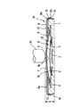
以下、本発明に係る押釦スイッチの第1実施形態例を、図1乃至図5に基づいて説明する。図1は第1実施形態例に係る押釦スイッチの非操作状態の断面図、図2は第1実施形態例に係る押釦スイッチに備えられる第2の導電性反転ばねの斜視図、図3は第1実施形態例に係る押釦スイッチの第1の接点切替状態を示す断面図、図4は第1実施形態例に係る押釦スイッチの第2の接点切替状態を示す断面図、図5は第1実施形態例に係る押釦スイッチの取付構造を示す断面図である。
【0024】
これらの図から明らかなように、本例の押釦スイッチ1Aは、浅底の箱形状を有する基体1と、当該基体1の所定の位置に設定された第1乃至第3の固定接点2,3,4と、前記第1の固定接点2と常時電気的に接続され、反転時に前記第2の固定接点3と電気的に接続される第1の導電性反転ばね5と、前記第3の固定接点4と常時電気的に接続され、反転時に前記第1の導電性反転ばね5と電気的に接続される第2の導電性反転ばね6と、当該第2の導電性反転ばね6の上面に被着された防塵シート7と、前記基体1の開口部側に被着された金属板製のフレーム8とから主に構成されており、前記フレーム8の中央部には、キートップ10の先端部を挿通するためのキートップ挿通孔9が開設されている。
【0025】
前記基体1は、絶縁性樹脂の成形体をもって平面形状が略正方形に形成されており、その片面には、前記第1の導電性反転ばね5の設定凹部11と前記第2の導電性反転ばね6の設定凹部12とが凹設され、相対向する2つの側面には、フレーム8をスナップ結合するための係止爪13が突設されている。前記第1の設定凹部11の中央部には前記第2の固定接点3が設定され、その外周部分には前記第1の固定接点2が設定されている。また、前記第2の設定凹部12の外周部分には、前記第3の固定接点4が設定されている。前記第1乃至第3の固定接点2,3,4は、インサートモールドにより前記基体1の所定部分に設定される。なお、図中の符号14は、前記第1乃至第3の固定接点2,3,4の端子部を示している。
【0026】
前記第1の導電性反転ばね5は、導電性及びばね弾性に優れた金属材料をもって、外周が前記第1の固定接点2と接触可能な大きさの円椀ドーム状に形成されている。この第1の導電性反転ばね5は、前記第1の設定凹部11内に収納された後、脱落防止用の接着テープ15を用いて前記基体1に反転動作可能に固定される。
【0027】
前記第2の導電性反転ばね6は、図2に示すように、円椀ドーム状に形成された膨出部6aと、前記第3の固定接点4と接触するフランジ部6bとから構成されており、前記膨出部6aの頂上部分には、キートップ10の先端部によって押圧操作される窪み状の操作部16が形成されている。この第2の導電性反転ばね6は、導電性及びばね弾性に優れた金属材料をもって形成される。
【0028】
前記防塵シート7は、片面に接着剤層(図示省略)を有する合成樹脂シートをもって形成されており、図示しない接着剤層を介して前記第2の導電性反転ばね6の上面と前記基体1の上面とに接着される。
【0029】
前記フレーム8は、キートップ挿通孔9が開設された上板8aと、当該上板8aの対向する2辺より下向きに折り下げられた側板8bとから形成されており、側板8bには前記基体1の側面に突設された係止爪13に係合するための係止爪係合部8cが形成されている。このフレーム8は、前記係止爪13に前記係止爪係合部8cをスナップ結合することによって前記基体1に取り付けられる。
【0030】
フレーム8が基体1に取り付けられたとき、図1に示すように、第2の導電性反転ばね6は、膨出部6aが前記防塵シート7を介して前記キートップ挿通孔9の開口端に当接され、前記基体1に反転動作可能に固定される。また、第2の導電性反転ばね6の操作部16は、前記キートップ挿通孔9内に設定され、かつ前記フレーム8の上面よりも上方に配置される。
【0031】
以下、前記のように構成された第1実施形態例に係る押釦スイッチ1Aの接点切替動作について説明する。
【0032】
本例の押釦スイッチ1Aは、非操作時においては、図1に示すように、第1の導電性反転ばね5が上向きに湾曲して第1の固定接点2と第2の固定接点3とが電気的に切離されている。また、第2の導電性反転ばね6も上向きに湾曲しており、第1の固定接点2及び第2の固定接点3と第3の固定接点4とが電気的に切離されている。
【0033】
この状態から、第2の導電性反転ばね6の操作部16をキートップ10によって押圧すると、第2の導電性反転ばね6の膨出部6aが下向きに弾性変形され、当該第2の導電性反転ばね6と第1の導電性反転ばね5とが接触した段階で第1の固定接点2と第3の固定接点4とが導通し、第1の接点切替状態になる。また、この状態からさらにキートップ10を押圧すると、その押圧力によって第1の導電性反転ばね5が下向きに反転し、これら第1及び第2の導電性反転ばね5,6を介して第1乃至第3の固定接点2,3,4が導通し、第2の接点切替状態になる。
【0034】
また、第1の接点切替状態又は第2の接点切替状態からキートップに加えられていた押圧力を除けば、第1及び第2の導電性反転ばね5,6の弾性力により、図1に示す非操作状態に自動的に復帰する。
【0035】
本例の押釦スイッチ1Aは、第1乃至第3の固定接点2,3,4を有する基体1と、第1及び第2の導電性反転ばね5,6と、防塵シート7と、フレーム8とから構成したので、従来例に係る押釦スイッチに備えられていたリーフバネを省略することができ、押釦スイッチの薄形化を図ることができる。また、第2の導電性反転ばね6の操作部16をフレーム8に開設されたキートップ挿通孔9内に設定し、かつ当該第2の導電性反転ばね6の操作部16をフレーム8の上面よりも上方に配置したので、第2の導電性反転ばね6の上方にフレーム8が配置されず、この点からも押釦スイッチの薄形化を図ることができる。よって、本例の押釦スイッチ1Aは、基体1の底面から第2の導電性反転ばね6の操作部16までの全高hを従来例に係る押釦スイッチに比べて格段に小さくすることができる。
【0036】
また、本例の押釦スイッチ1Aは、第2の導電性反転ばね6の上面を防塵シート7で覆ったので、スイッチ装置内への塵埃等の異物の侵入を防止でき、押釦スイッチの耐久性を高めることができる。
【0037】
また、本例の押釦スイッチ1Aは、第2の導電性反転ばね6に膨出部6aを形成し、フレーム8に開設されたキートップ挿通孔9の開口端に当該膨出部6aを当接したので、電気機器への押釦スイッチの組み込み時、電気機器の筐体に弾性保持されたキートップ10の下端部をフレーム8の上面に当接した状態から押釦スイッチをキートップ10の操作方向に対して直交する方向に移動させたときに、キートップ10の下端部をフレーム8上から第2の導電性反転ばね6の膨出部6a上に円滑に移動させることができ、電気機器に対する押釦スイッチの組み込みを円滑に行うことができる。
【0038】
また、本例の押釦スイッチ1Aは、第2の導電性反転ばね6の膨出部6aを円椀ドーム状に形成したので、電気機器への押釦スイッチの組み込み時に、キートップ10に対する第2の導電性反転ばね6の移動方向に方向性をなくすことができ、電気機器に対する押釦スイッチの組み込みを容易なものにすることができる。
【0039】
さらに、本例の押釦スイッチ1Aは、基体1とフレーム8とをスナップ結合するので、基体1に対するフレーム8の組立を容易化することができ、押釦スイッチの低コスト化を図ることができると共に、電気機器への押釦スイッチの組み込み時にフレーム8の上面にキートップ10を弾接して摺動させても、その摩擦力によってフレーム8が位置ずれを起こすということがなく、電気機器に対する押釦スイッチの組み込みを容易かつ確実なものにすることができる。
【0040】
以下、前記のように構成された押釦スイッチ1Aの電気機器に対する取付構造を、図5に基づいて説明する。
【0041】
図5に示すように、押釦スイッチ1Aは、プリント配線基板21に実装される。一方、電気機器の筐体22の上面22aには、第1及び第2の導電性反転ばね5,6を操作するためのキートップ10が、垂直下向きに付勢されて弾性保持されている。また、当該筐体21の内部には、前記押釦スイッチ1A及びプリント配線基板21を横方向より挿入可能なスイッチ挿入空間23が前記筐体22の上面22aと平行に設けられており、当該スイッチ挿入空間23内には、電気機器に備えられた電気回路(図示省略)に接続された導電性のクリップ24が設定されている。前記キートップ10の下端部は、前記スイッチ挿入空間23内に挿入された押釦スイッチ1Aのフレーム上面8aよりもやや低い位置になるように設定される。
【0042】
このように構成された押釦スイッチの取付構造において、スイッチ挿入空間23内にプリント配線基板21に実装された押釦スイッチ1Aを挿入すると、まずキートップ10の下端部がフレーム8の上板8aと側板8bとの角部に当接する。この状態から押釦スイッチ1Aをさらに挿入すると、その挿入力によってキートップ10が図示しない付勢部材の弾性力に抗して上昇してフレーム8の上面に乗り上げ、フレーム8の上面上を摺動する。そして、キートップ10がフレーム8の上板8aに開設されたキートップ挿通孔9を超えた段階で第2の導電性反転ばね6側に移行する。この状態から押釦スイッチ1Aをさらに挿入すると、その挿入力によってキートップ10が図示しない付勢部材の弾性力に抗して上昇し、第2の導電性反転ばね6の弧面に沿って上昇する。また、この過程で、プリント配線基板21がクリップ24に挟み込まれる。そして、プリント配線基板21がクリップ24の停止端と衝合した段階で、キートップ10の下端部が第2の導電性反転ばね6の操作部16に当接される。これによって、第2の導電性反転ばね6の予圧並びにプリント配線基板21と電気機器に備えられた電気回路との電気的接続とが同時に完了する。
【0043】
このように、本例の押釦スイッチの取付構造は、筐体22の上面22aにキートップ10を垂直に弾性保持すると共に筐体22の内部に押釦スイッチ1Aを横方向から挿入可能なスイッチ挿入空間23を設け、押釦スイッチ1Aをスイッチ挿入空間23内の所定位置まで挿入したときに、キートップ10の先端部が第2の導電性反転ばね6の操作部16に弾接され、かつ押釦スイッチ1Aに備えられた第1乃至第3の固定接点2,3,4が筐体22内に収納された電気回路と電気的に接続されるようにしたので、単に電気機器の筐体22に設けられたスイッチ挿入空間23内に押釦スイッチ1Aを挿入するだけで自動的にキートップ10による第2の導電性反転ばね6への予圧負荷と必要な電気回路の接続とを完了できるので、電気機器に対する押釦スイッチ1Aの組み込み工程の簡略化を図ることができる。また、キートップ10の操作方向に対して直交する方向からの押釦スイッチ1Aの装着が可能になることから、電気機器における押釦スイッチ設定スペース周りのレイアウトの自由度を高めることができる。
【0044】
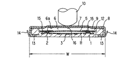
次に、本発明に係る押釦スイッチの第2実施形態例を、図6及び図7に基づいて説明する。図6は第2実施形態例に係る押釦スイッチの非操作状態の断面図、図7は第2実施形態例に係る押釦スイッチに備えられる第2の導電性反転ばねの斜視図である。
【0045】
第2実施形態例に係る押釦スイッチ1Bは、図6に示すように、第2の導電性反転ばね6として、短冊状のものを用いたことを特徴とする。その他については、第1実施形態例に係る押釦スイッチ1Aと同じであるので、図6の対応部分に同一の符号を付して説明を省略する。
【0046】
本例の押釦スイッチ1Bは、図6から明らかなように、第2の導電性反転ばね6として膨出部6aが短冊状のものを用いたので、ドーム状のものを用いた場合に比べて基体1及びフレーム8の横幅Wを小さくすることができ、押釦スイッチの小型化を図ることができる。
【0047】
電気機器の筐体に対する取付構造については、第1実施形態例に係る押釦スイッチ1Aとほぼ同じであるので、説明を省略する。但し、第2実施形態例に係る押釦スイッチ1Bについては、キートップ10の脱落を防止するため、スイッチ挿入空間23内への押釦スイッチ1Bの挿入を、短冊状に形成された第2の導電性反転ばね6の長手方向に沿って行う必要がある。
【0048】
なお、前記実施形態例に係る押釦スイッチ1A,1Bにおいては、防塵シート7を備えたが、塵埃等による汚染が問題にならない場合には、この防塵シート7を省略することもできる。
【0049】
【発明の効果】
以上説明したように、本発明の押釦スイッチは、第1乃至第3の固定接点を有する基体と、第1及び第2の導電性反転ばねと、フレーム8とから構成したので、従来例に係る押釦スイッチに備えられていたリーフバネを省略することができ、押釦スイッチの薄形化を図ることができる。また、第2の導電性反転ばねの操作部をフレームに開設されたキートップ挿通孔内に設定し、かつ当該第2の導電性反転ばねの操作部をフレームの上面よりも上方に配置したので、第2の導電性反転ばねの上方にフレームが配置されず、この点からも押釦スイッチの薄形化を図ることができる。よって、押釦スイッチの全高hを従来例に係る押釦スイッチに比べて格段に小さくすることができる。
【0050】
また、本発明の押釦スイッチの取付構造は、筐体の一面にキートップを弾性保持すると共に筐体の内部に押釦スイッチを前記筐体の一面と平行に挿入可能な押釦スイッチの挿入空間を設け、押釦スイッチを空間内の所定位置まで挿入したとき、キートップの先端部が第2の導電性反転ばねの操作部に弾接され、かつ押釦スイッチに備えられた第1乃至第3の固定接点が電気機器の筐体内に収納された電気回路と電気的に接続されるようにしたので、単に電気機器の筐体に設けられた押釦スイッチの挿入空間内に押釦スイッチを挿入するだけで自動的にキートップによる第2の導電性反転ばねへの予圧負荷と必要な電気回路の接続とを完了することができ、電気機器に対する押釦スイッチの組み込み工程の簡略化を図ることができる。また、キートップの操作方向に対して直交する方向からの押釦スイッチの装着が可能になることから、電気機器における押釦スイッチ設定スペース周りのレイアウトの自由度を高めることができる。
【図面の簡単な説明】
【図1】第1実施形態例に係る押釦スイッチの非操作状態の断面図である。
【図2】第1実施形態例に係る押釦スイッチに備えられる第2の導電性反転ばねの斜視図である。
【図3】第1実施形態例に係る押釦スイッチの第1の接点切替状態を示す断面図である。
【図4】第1実施形態例に係る押釦スイッチの第2の接点切替状態を示す断面図である。
【図5】第1実施形態例に係る押釦スイッチの取付構造を示す断面図である。
【図6】第2実施形態例に係る押釦スイッチの非操作状態の断面図である。
【図7】第2実施形態例に係る押釦スイッチに備えられる第2の導電性反転ばねの斜視図である。
【図8】従来例に係る押釦スイッチの断面図である。
【符号の説明】
1A,1B 押釦スイッチ
1 基体
2 第1の固定接点
3 第2の固定接点
4 第3の固定接点
5 第1の導電性反転ばね
6 第2の導電性反転ばね
7 防塵シート
8 フレーム
9 キートップ挿通孔
10 キートップ
21 プリント配線基板
22 電気機器の筐体
23 スイッチ挿入空間
24 クリップ[0001]
TECHNICAL FIELD OF THE INVENTION
The present invention relates to a push-button switch and a mounting structure thereof, and more particularly, to a configuration of a two-stage operation switch incorporated in a camera or the like having an auto-focus function, and mounting of the two-stage operation switch on a housing of an electric device such as a camera. Regarding the structure.
[0002]
[Prior art]
FIG. 8 shows an example of this type of conventionally known push button switch. As is apparent from this figure, the push button switch of the present example has a
[0003]
In the push button switch of this example, when not operated, as shown in FIG. 8, the conductive dish-shaped inverting
[0004]
The contact switching of the push button switch is performed by pressing a key top (not shown) having a leading end abutting on the center of the outer surface of the
[0005]
Excluding the pressing force applied to the key top from the first contact switching state or the second contact switching state, the elastic force of the conductive dish-shaped
[0006]
[Problems to be solved by the invention]
However, in the push button switch according to the conventional example, since the
[0007]
In addition, this type of push button switch prevents the key top provided in the housing of the electric device from swinging, and in order to improve the usability of the push button switch, the key top is elastically contacted with the outer surface of the
[0008]
The present invention has been made to solve such a technical problem, and an object thereof is to provide a push button switch which is thin and easy to attach to an electric device, and a push button for an electric device. It is an object of the present invention to provide a push button switch mounting structure that can facilitate switch mounting.
[0009]
[Means for Solving the Problems]
In order to solve the above problems, the present invention relates to a push button switch, in which a base having first to third fixed contacts and the first fixed contact are always electrically connected to each other, A first conductive reversing spring electrically connected to the fixed contact; and a first conductive reversing spring that is always electrically connected to the third fixed contact and is electrically connected to the first conductive reversing spring when reversing. And a frame for operably holding the second conductive inversion spring between the base and the base, wherein an operation unit of the second conductive inversion spring is opened in the frame. And the operation portion of the second conductive reversing spring is disposed above the upper surface of the frame.
[0010]
As described above, when the push button switch is configured by the base having the first to third fixed contacts, the first and second conductive reversing springs, and the frame, the push button switch according to the conventional example is provided. Since the leaf spring can be omitted, the thickness of the push button switch can be reduced. Further, when the operating portion of the second conductive reversing spring is set in the key top insertion hole formed in the frame, and the operating portion of the second conductive reversing spring is disposed above the upper surface of the frame, Since the frame is not arranged above the second conductive reversing spring, the push button switch can be made thinner from this point as well. Further, the operating portion of the second conductive reversing spring is set in the key top insertion hole formed in the frame, and the operating portion of the second conductive reversing spring is disposed above the upper surface of the frame. By inserting the push button switch into the housing from a direction perpendicular to the operation direction of the key top in a state where the lower end of the key top elastically held by the housing of the electric device is in contact with the upper surface of the frame, A preload can be automatically applied to the second conductive reversing spring, which simplifies the process of assembling the pushbutton switch into the electric device and increases the degree of freedom in layout around the pushbutton switch setting space in the electric device. it can.
[0011]
Further, according to the present invention, in the push button switch having the above configuration, the upper surface of the second conductive reversing spring is covered with a dustproof sheet, and the surface of the dustproof sheet is passed through a keytop insertion hole formed in the frame. It is configured to be located above the above.
[0012]
As described above, when the upper surface of the second conductive reversing spring is covered with the dustproof sheet, entry of foreign matter such as dust into the switch device can be prevented, so that the durability of the push button switch can be increased.
[0013]
The present invention also provides the push-button switch having the above-described configuration, wherein at least a part of the second conductive reversing spring forms a bulged portion having a circular cross-sectional shape, and a top portion thereof serves as the operating portion. The bulging portion is configured to contact the opening end of the key top insertion hole formed in the frame directly or via the dustproof sheet.
[0014]
Thus, when the arc-shaped bulging portion is formed in the second conductive reversing spring and the bulging portion comes into contact with the opening end of the key top insertion hole formed in the frame, the push button switch to the electric device is formed. At the time of the incorporation, when the push button switch is moved in a direction orthogonal to the operation direction of the key top from a state where the lower end of the key top elastically held by the housing of the electric device is in contact with the upper surface of the frame, Since the lower end of the key top can be moved smoothly from the frame onto the bulging portion of the second conductive reversing spring, the push button switch can be smoothly incorporated into the electric device.
[0015]
Further, according to the present invention, in the push button switch having the above configuration, the bulging portion of the second conductive reversing spring is formed in a dome shape.
[0016]
As described above, when the bulging portion of the second conductive reversing spring is formed in a dome shape, the direction of movement of the second conductive reversing spring with respect to the keytop is lost when the push button switch is incorporated into the electric device. Therefore, it is possible to easily incorporate the push button switch into the electric device.
[0017]
Further, according to the present invention, in the push button switch having the above configuration, the bulging portion of the second conductive inversion spring is formed in a strip shape.
[0018]
As described above, when the bulging portion of the second conductive reversing spring is formed in a strip shape, the lateral width of the base and the frame can be reduced as compared with the case where the bulging portion is formed in a dome shape. Can be planned.
[0019]
Further, according to the present invention, in the push button switch having the above configuration, a locking claw and a locking claw engaging portion for snap connection are formed on the base and the frame, and the frame is snap-connected to the base. Was configured.
[0020]
As described above, when the base and the frame are snap-coupled, the assembly of the frame to the base can be facilitated, the cost of the push button switch can be reduced, and the frame can be mounted when the push button switch is incorporated into the electric device. Even when the key top is resiliently slid on the upper surface and slides, the frame does not shift due to the frictional force, and the push button switch can be easily and reliably incorporated into the electric device.
[0021]
On the other hand, according to the present invention, in order to solve the above-mentioned problem, with respect to the mounting structure of the push button switch, the base having the first to third fixed contacts, and the first fixed contact are always electrically connected to each other, A first conductive inversion spring that is electrically connected to the second fixed contact at times, and is always electrically connected to the third fixed contact, and is electrically connected to the first conductive inversion spring when inverted. A second conductive reversing spring connected to the main body, and a frame that operably holds the second conductive reversing spring between the base and an operating part of the second conductive reversing spring. A push button switch, which is set in a key top insertion hole formed in the frame, and in which an operation portion of the second conductive reversing spring is disposed above the upper surface of the frame, comprises a key top of the push button switch. To the housing of electrical equipment equipped with Mounting structure of the push button switch, wherein the key top is elastically held on one surface of the housing, and the push button switch is inserted into the housing in parallel with the one surface of the housing. When a space is provided and the push button switch is inserted to a predetermined position in the space, the tip of the key top is elastically contacted with the operating portion of the second conductive reversing spring, and the first to the third The fixed contact is electrically connected to an electric circuit housed in the housing.
[0022]
As described above, the key top is elastically held on one surface of the housing, and the insertion space for the push button switch in which the push button switch can be inserted in parallel with the one surface of the housing is provided inside the housing. When the key top is inserted to the position, the tip of the key top is elastically contacted with the operating portion of the second conductive reversing spring, and the first to third fixed contacts provided on the push button switch are housed in the housing of the electric device. When the mounting structure of the push button switch is configured to be electrically connected to the electrical circuit, the key is automatically inserted simply by inserting the push button switch into the insertion space of the push button switch provided in the housing of the electric device. Since the preloading of the second conductive reversing spring by the top and the connection of the necessary electric circuit can be completed, the process of assembling the push button switch to the electric device can be simplified. Further, since the push button switch can be mounted in a direction orthogonal to the key top operation direction, the degree of freedom in layout around the space for setting the push button switch in the electric device can be increased.
[0023]
BEST MODE FOR CARRYING OUT THE INVENTION
Hereinafter, a first embodiment of a push button switch according to the present invention will be described with reference to FIGS. FIG. 1 is a sectional view of the push-button switch according to the first embodiment in a non-operating state, FIG. 2 is a perspective view of a second conductive reversing spring provided in the push-button switch according to the first embodiment, and FIG. FIG. 4 is a cross-sectional view showing a first contact switching state of the push button switch according to the first embodiment, FIG. 4 is a cross-sectional view showing a second contact switching state of the push button switch according to the first embodiment, and FIG. It is sectional drawing which shows the mounting structure of the pushbutton switch which concerns on a form example.
[0024]
As is clear from these figures, the
[0025]
The
[0026]
The first conductive reversing
[0027]
As shown in FIG. 2, the second conductive reversing
[0028]
The
[0029]
The
[0030]
When the
[0031]
Hereinafter, the contact switching operation of the
[0032]
When the
[0033]
In this state, when the operating
[0034]
Except for the pressing force applied to the key top from the first contact switching state or the second contact switching state, the elastic force of the first and second conductive reversing
[0035]
The
[0036]
In addition, since the
[0037]
Further, the
[0038]
Further, in the
[0039]
Furthermore, since the
[0040]
Hereinafter, the mounting structure of the
[0041]
As shown in FIG. 5, the
[0042]
In the push button switch mounting structure thus configured, when the
[0043]
As described above, the mounting structure of the push button switch according to the present embodiment has a switch insertion space in which the key top 10 is vertically elastically held on the
[0044]
Next, a second embodiment of the push button switch according to the present invention will be described with reference to FIGS. FIG. 6 is a sectional view of the push-button switch according to the second embodiment in a non-operating state, and FIG. 7 is a perspective view of a second conductive reversing spring provided in the push-button switch according to the second embodiment.
[0045]
As shown in FIG. 6, a push button switch 1B according to the second embodiment is characterized in that a strip-shaped second conductive reversing
[0046]
As is apparent from FIG. 6, the push-button switch 1B of the present example uses a strip-shaped bulging
[0047]
The mounting structure of the electric device with respect to the housing is substantially the same as that of the
[0048]
Although the push button switches 1A and 1B according to the embodiment have the
[0049]
【The invention's effect】
As described above, the push-button switch of the present invention includes the base having the first to third fixed contacts, the first and second conductive reversing springs, and the
[0050]
In addition, the mounting structure of the push button switch of the present invention is provided with an insertion space for the push button switch that can elastically hold the key top on one surface of the housing and insert the push button switch inside the housing in parallel with the one surface of the housing. When the push button switch is inserted to a predetermined position in the space, the tip of the key top is elastically contacted with the operating portion of the second conductive reversing spring, and the first to third fixed contacts provided in the push button switch Is electrically connected to the electrical circuit housed in the housing of the electrical equipment, so that simply inserting the pushbutton switch into the insertion space of the pushbutton switch provided in the housing of the electrical equipment automatically In addition, the preloading of the second conductive reversing spring by the key top and the connection of the necessary electric circuit can be completed, and the process of mounting the push button switch on the electric device can be simplified. Further, since the push button switch can be mounted in a direction orthogonal to the key top operation direction, the degree of freedom of layout around the space for setting the push button switch in the electric device can be increased.
[Brief description of the drawings]
FIG. 1 is a sectional view of a non-operating state of a push button switch according to a first embodiment.
FIG. 2 is a perspective view of a second conductive reversing spring provided in the push button switch according to the first embodiment.
FIG. 3 is a cross-sectional view illustrating a first contact switching state of the push button switch according to the first embodiment.
FIG. 4 is a sectional view showing a second contact switching state of the push button switch according to the first embodiment.
FIG. 5 is a cross-sectional view illustrating a mounting structure of the push button switch according to the first embodiment.
FIG. 6 is a sectional view of a non-operated state of a push button switch according to a second embodiment.
FIG. 7 is a perspective view of a second conductive reversing spring provided in the push button switch according to the second embodiment.
FIG. 8 is a sectional view of a push button switch according to a conventional example.
[Explanation of symbols]
1A, 1B push button switch
1 Substrate
2 First fixed contact
3 Second fixed contact
4. Third fixed contact
5. First conductive reversing spring
6. Second conductive reversing spring
7 Dustproof sheet
8 frames
9 Key top insertion hole
10 key tops
21 Printed wiring board
22 Housing for electrical equipment
23 Switch insertion space
24 clips
Claims (7)
Priority Applications (2)
| Application Number | Priority Date | Filing Date | Title |
|---|---|---|---|
| JP2002270277A JP2004111148A (en) | 2002-09-17 | 2002-09-17 | Push button switch and mounting structure therefor |
| CN 03158505 CN1242438C (en) | 2002-09-17 | 2003-09-17 | Button switch and mounting structure thereof |
Applications Claiming Priority (1)
| Application Number | Priority Date | Filing Date | Title |
|---|---|---|---|
| JP2002270277A JP2004111148A (en) | 2002-09-17 | 2002-09-17 | Push button switch and mounting structure therefor |
Publications (1)
| Publication Number | Publication Date |
|---|---|
| JP2004111148A true JP2004111148A (en) | 2004-04-08 |
Family
ID=32267959
Family Applications (1)
| Application Number | Title | Priority Date | Filing Date |
|---|---|---|---|
| JP2002270277A Pending JP2004111148A (en) | 2002-09-17 | 2002-09-17 | Push button switch and mounting structure therefor |
Country Status (2)
| Country | Link |
|---|---|
| JP (1) | JP2004111148A (en) |
| CN (1) | CN1242438C (en) |
Cited By (2)
| Publication number | Priority date | Publication date | Assignee | Title |
|---|---|---|---|---|
| JP2007005103A (en) * | 2005-06-23 | 2007-01-11 | Teikoku Tsushin Kogyo Co Ltd | Method for mounting keytop to push switch part, and push switch part |
| WO2014175446A1 (en) * | 2013-04-26 | 2014-10-30 | シチズン電子株式会社 | Push switch and switch module |
Families Citing this family (2)
| Publication number | Priority date | Publication date | Assignee | Title |
|---|---|---|---|---|
| JP4371987B2 (en) * | 2004-12-07 | 2009-11-25 | ホシデン株式会社 | Push-on switch |
| JP4513688B2 (en) * | 2005-08-17 | 2010-07-28 | パナソニック株式会社 | Push-on switch |
-
2002
- 2002-09-17 JP JP2002270277A patent/JP2004111148A/en active Pending
-
2003
- 2003-09-17 CN CN 03158505 patent/CN1242438C/en not_active Expired - Fee Related
Cited By (4)
| Publication number | Priority date | Publication date | Assignee | Title |
|---|---|---|---|---|
| JP2007005103A (en) * | 2005-06-23 | 2007-01-11 | Teikoku Tsushin Kogyo Co Ltd | Method for mounting keytop to push switch part, and push switch part |
| WO2014175446A1 (en) * | 2013-04-26 | 2014-10-30 | シチズン電子株式会社 | Push switch and switch module |
| JPWO2014175446A1 (en) * | 2013-04-26 | 2017-02-23 | シチズン電子株式会社 | Push switch and switch module |
| US9793072B2 (en) | 2013-04-26 | 2017-10-17 | Citizen Electronics Co., Ltd. | Push switch and switch module |
Also Published As
| Publication number | Publication date |
|---|---|
| CN1242438C (en) | 2006-02-15 |
| CN1490833A (en) | 2004-04-21 |
Similar Documents
| Publication | Publication Date | Title |
|---|---|---|
| JP3896707B2 (en) | Panel switch and its mounting method | |
| JP4716988B2 (en) | Electrical switch | |
| US8054293B2 (en) | Electronic apparatus | |
| JP3944975B2 (en) | Push-on switch | |
| JP4169983B2 (en) | Multi-directional input device | |
| JP2004111148A (en) | Push button switch and mounting structure therefor | |
| JP2005294112A (en) | Switching device | |
| JPH113630A (en) | Push switch and assembly thereof | |
| JP3936852B2 (en) | Slide operation switch | |
| KR920003203B1 (en) | Push-button switch | |
| JP2022043622A (en) | Push switch | |
| JP3802298B2 (en) | Switch device | |
| JP2000294079A (en) | Push-on switch | |
| JP4008648B2 (en) | Push button switch | |
| JP2007053029A (en) | Rotary electronic component with push switch mechanism | |
| JP4044395B2 (en) | Push button switch | |
| JP4172993B2 (en) | Input device | |
| JP3772531B2 (en) | Push button device | |
| JP2550817Y2 (en) | Moderation push-on switch | |
| JPH0635321Y2 (en) | Push button switch | |
| JPS6110277Y2 (en) | ||
| JP3875476B2 (en) | Push button switch | |
| JP2001256860A (en) | Waterproof switch device | |
| JP2557784Y2 (en) | Tact switch | |
| JPH073542Y2 (en) | Keyboard switch |
Legal Events
| Date | Code | Title | Description |
|---|---|---|---|
| A621 | Written request for application examination |
Effective date: 20050415 Free format text: JAPANESE INTERMEDIATE CODE: A621 |
|
| A977 | Report on retrieval |
Free format text: JAPANESE INTERMEDIATE CODE: A971007 Effective date: 20070829 |
|
| A131 | Notification of reasons for refusal |
Free format text: JAPANESE INTERMEDIATE CODE: A131 Effective date: 20070904 |
|
| A521 | Written amendment |
Effective date: 20071024 Free format text: JAPANESE INTERMEDIATE CODE: A523 |
|
| A02 | Decision of refusal |
Free format text: JAPANESE INTERMEDIATE CODE: A02 Effective date: 20080304 |